Transcription
Instructor’s Manualto accompanyChapmanElectric Machinery FundamentalsFourth EditionStephen J. ChapmanBAE SYSTEMS Australiai
Instructor’s Manual to accompany Electric Machinery Fundamentals, Fourth EditionCopyright 2004 McGraw-Hill, Inc.All rights reserved. Printed in the United States of America. No part of this book may be used or reproduced inany manner whatsoever without written permission, with the following exception: homework solutions may becopied for classroom use.ISBN: ?ii
TABLE OF CONTENTSCHAPTER 1:INTRODUCTION TO MACHINERY PRINCIPLESCHAPTER 2:TRANSFORMERS23CHAPTER 3:INTRODUCTION TO POWER ELECTRONICS63CHAPTER 4:AC MACHINERY FUNDAMENTALS103CHAPTER 5:SYNCHRONOUS GENERATORS109CHAPTER 6:SYNCHRONOUS MOTORS149CHAPTER 7:INDUCTION MOTORS171CHAPTER 8:DC MACHINERY FUNDAMENTALS204CHAPTER 9:DC MOTORS AND GENERATORS214CHAPTER 10:SINGLE-PHASE AND SPECIAL-PURPOSE MOTORS1270APPENDIX A: REVIEW OF THREE-PHASE CIRCUITS280APPENDIX B:288COIL PITCH AND DISTRIBUTED WINDINGSAPPENDIX C: SALIENT POLE THEORY OF SYNCHRONOUS MACHINES295APPENDIX D: ERRATA FOR ELECTRIC MACHINERY FUNDAMENTALS 4/E301iii
PREFACETO THE INSTRUCTORThis Instructor’s Manual is intended to accompany the fourth edition of Electric Machinery Fundamentals. Tomake this manual easier to use, it has been made self-contained. Both the original problem statement and theproblem solution are given for each problem in the book. This structure should make it easier to copy pages fromthe manual for posting after problems have been assigned.Many of the problems in Chapters 2, 5, 6, and 9 require that a student read one or more values from amagnetization curve. The required curves are given within the textbook, but they are shown with relatively fewvertical and horizontal lines so that they will not appear too cluttered. Electronic copies of the corresponding opencircuit characteristics, short-circuit characteristics, and magnetization curves as also supplied with the book. Theyare supplied in two forms, as MATLAB MAT-files and as ASCII text files. Students can use these files forelectronic solutions to homework problems. The ASCII files are supplied so that the information can be used withnon-MATLAB software.Please note that the file extent of the magnetization curves and open-circuit characteristics have changed in thisedition. In the Third Edition, I used the file extent *.mag for magnetization curves. Unfortunately, after the bookwas published, Microsoft appropriated that extent for a new Access table type in Office 2000. That made it hardfor users to examine and modify the data in the files. In this edition, all magnetization curves, open-circuitcharacteristics, short-circuit characteristics, etc. use the file extent *.dat to avoid this problem.Each curve is given in ASCII format with comments at the beginning. For example, the magnetization curve inFigure P9-1 is contained in file p91 mag.dat. Its contents are shown below:%%%%%%%%%%This is the magnetization curve shown in FigureP9-1. The first column is the field current inamps, and the second column is the internalgenerated voltage in volts at a speed of 1200 r/min.To use this file in MATLAB, type "load p91 mag.dat".The data will be loaded into an N x 2 array named"p91 mag", with the first column containing If andthe second column containing the open-circuit voltage.MATLAB function "interp1" can be used to recovera value from this 460.13360.260.16775.060.289.74iv
82289.2289.375289.567289.689289.811289.950To use this curve in a MATLAB program, the user would include the following statements in the program:% Get the magnetization curve. Note that this curve is% defined for a speed of 1200 r/min.load p91 mag.datif values p91 mag(:,1);ea values p91 mag(:,2);n 0 1200;Unfortunately, an error occurred during the production of this book, and the values (resistances, voltages, etc.) insome end-of-chapter artwork are not the same as the values quoted in the end-of-chapter problem text. I haveattached corrected pages showing each discrepancy in Appendix D of this manual. Please print these pages anddistribute them to your students before assigning homework problems. (Note that this error will be corrected at thesecond printing, so it may not be present in your student’s books.)v
The solutions in this manual have been checked carefully, but inevitably some errors will have slipped through. Ifyou locate errors which you would like to see corrected, please feel free to contact me at the address shown below,or at my email address schapman@tpgi.com.au. I greatly appreciate your input! My physical and emailaddresses may change from time to time, but my contact details will always be available at the book’s Web site,which is http://www.mhhe.com/engcs/electrical/chapman/.I am also contemplating a homework problem refresh, with additional problems added on the book’s Web site midway through the life of this edition. If that feature would be useful to you, please provide me with feedback aboutwhich problems that you actually use, and the areas where you would like to have additional exercises. Thisinformation can be passed to the email address given below, or alternately via you McGraw-Hill representative.Thank you.Stephen J. ChapmanMelbourne, AustraliaJanuary 4, 2004Stephen J. Chapman278 Orrong RoadCaulfield North, VIC 3161AustraliaPhone 61-3-9527-9372vi
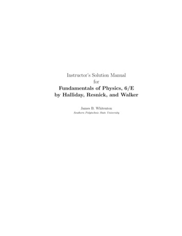
Chapter 1: Introduction to Machinery Principles1-1.A motor’s shaft is spinning at a speed of 3000 r/min. What is the shaft speed in radians per second?SOLUTION The speed in radians per second is 1 min 2π rad 314.2 rad/s 60 s 1 r ω ( 3000 r/min ) 1-2.A flywheel with a moment of inertia of 2 kg m2 is initially at rest. If a torque of 5 N m(counterclockwise) is suddenly applied to the flywheel, what will be the speed of the flywheel after 5 s?Express that speed in both radians per second and revolutions per minute.SOLUTION The speed in radians per second is:5 N m τ ω α t t ( 5 s ) 12.5 rad/sJ2kg m 2 The speed in revolutions per minute is: 1 r 60 s n (12.5 rad/s ) 119.4 r/min 2π rad 1 min 1-3.A force of 5 N is applied to a cylinder, as shown in Figure P1-1. What are the magnitude and direction ofthe torque produced on the cylinder? What is the angular acceleration α of the cylinder?SOLUTION The magnitude and the direction of the torque on this cylinder is:τ ind rF sin θ , CCWτ ind ( 0.25 m)(10 N ) sin 30 1.25 N m, CCWThe resulting angular acceleration is:α 1-4.τJ 1.25 N m 0.25 rad/s25 kg m 2A motor is supplying 60 N m of torque to its load. If the motor’s shaft is turning at 1800 r/min, what isthe mechanical power supplied to the load in watts? In horsepower?SOLUTION The mechanical power supplied to the load isP τω ( 60 N m )(1800 r/min )2π rad 11,310 W1r1 min60 s1
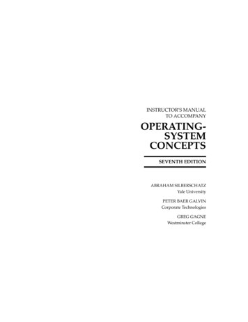
P (11,310 W )1-5.1 hp 15.2 hp746 WA ferromagnetic core is shown in Figure P1-2. The depth of the core is 5 cm. The other dimensions of thecore are as shown in the figure. Find the value of the current that will produce a flux of 0.005 Wb. Withthis current, what is the flux density at the top of the core? What is the flux density at the right side of thecore? Assume that the relative permeability of the core is 1000.SOLUTION There are three regions in this core. The top and bottom form one region, the left side forms asecond region, and the right side forms a third region. If we assume that the mean path length of the flux isin the center of each leg of the core, and if we ignore spreading at the corners of the core, then the pathlengths are l1 2(27.5 cm) 55 cm, l 2 30 cm, and l3 30 cm. The reluctances of these regions are:R1 ll0.55 m 58.36 kA t/Wb 7µ A µr µo A (1000) 4π 10 H/m ( 0.05 m )(0.15 m )R2 ll0.30 m 47.75 kA t/Wb 7µ A µr µo A (1000 ) 4π 10 H/m (0.05 m )( 0.10 m )R3 ll0.30 m 95.49 kA t/Wb 7µ A µ r µo A (1000) 4π 10 H/m ( 0.05 m )( 0.05 m )()()()The total reluctance is thusRTOT R1 R2 R3 58.36 47.75 95.49 201.6 kA t/Wband the magnetomotive force required to produce a flux of 0.003 Wb isF φ R ( 0.005 Wb )( 201.6 kA t/Wb ) 1008 A tand the required current isi F 1008 A t 2.52 AN400 tThe flux density on the top of the core isB φA 0.005 Wb 0.67 T0.15m )( 0.05 m )(2
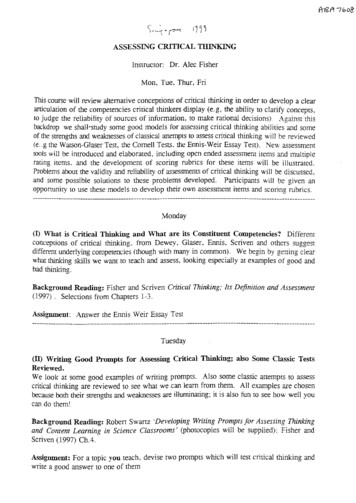
The flux density on the right side of the core isB 1-6.φA 0.005 Wb 2.0 T(0.05 m )(0.05 m)A ferromagnetic core with a relative permeability of 1500 is shown in Figure P1-3. The dimensions are asshown in the diagram, and the depth of the core is 7 cm. The air gaps on the left and right sides of the coreare 0.070 and 0.020 cm, respectively. Because of fringing effects, the effective area of the air gaps is 5percent larger than their physical size. If there are 4001 turns in the coil wrapped around the center leg ofthe core and if the current in the coil is 1.0 A, what is the flux in each of the left, center, and right legs ofthe core? What is the flux density in each air gap?SOLUTION This core can be divided up into five regions. Let R1 be the reluctance of the left-hand portionof the core, R2 be the reluctance of the left-hand air gap, R3 be the reluctance of the right-hand portion ofthe core, R4 be the reluctance of the right-hand air gap, and R5 be the reluctance of the center leg of thecore. Then the total reluctance of the core isRTOT R5 R1 R2 R3 R4 R5 l1µ r µ0 A1( R1 R2 ) ( R3 R4 )R1 R2 R3 R4 1.11 m 90.1 kA t/Wb(2000) 4π 10 H/m (0.07 m )(0.07 m )( 7)l20.0007 m 108.3 kA t/Wb 7µ0 A24π 10 H/m ( 0.07 m)(0.07 m )(1.05)(l3µr µ0 A3 )1.11 m 90.1 kA t/Wb(2000) 4π 10 H/m (0.07 m )(0.07 m)( 7)l40.0005 m 77.3 kA t/Wb 7µ0 A44π 10 H/m (0.07 m )( 0.07 m )(1.05)(l5µr µ0 A5 )0.37 m 30.0 kA t/Wb(2000) 4π 10 H/m (0.07 m)(0.07 m )( 7)The total reluctance is1In the first printing, this value was given incorrectly as 300.3
RTOT R5 ( R1 R2 ) ( R3 R4 ) 30.0 (90.1 108.3)(90.1 77.3) 120.8 kA t/WbR1 R2 R3 R490.1 108.3 90.1 77.3The total flux in the core is equal to the flux in the center leg:φcenter φTOT (400 t )(1.0 A ) 0.0033 WbF RTOT 120.8 kA t/WbThe fluxes in the left and right legs can be found by the “flux divider rule”, which is analogous to thecurrent divider rule.φleft ( R3 R4 )R1 R2 R3 R4( R1 R2 )φ right φTOT R1 R2 R3 R4(90.1 77.3)90.1 108.3 90.1 77.3φTOT (90.1 108.3)(0.0033 Wb) 0.00193 Wb90.1 108.3 90.1 77.3(0.0033 Wb) 0.00229 WbThe flux density in the air gaps can be determined from the equation φ BA :Bleft φleftBright 1-7.Aeff φ rightAeff0.00193 Wb(0.07 cm )(0.07 cm )(1.05) 0.375 T0.00229 Wb 0.445 T0.07cm()(0.07 cm )(1.05)A two-legged core is shown in Figure P1-4. The winding on the left leg of the core (N1) has 400 turns, andthe winding on the right (N2) has 300 turns. The coils are wound in the directions shown in the figure. Ifthe dimensions are as shown, then what flux would be produced by currents i1 0.5 A and i2 0.75 A?Assume µ r 1000 and constant.4
SOLUTION The two coils on this core are would so that their magnetomotive forces are additive, so the totalmagnetomotive force on this core isFTOT N1i1 N 2i2 ( 400 t )( 0.5 A ) ( 300 t )(0.75 A ) 425 A tThe total reluctance in the core isl2.60 mRTOT 92.0 kA t/Wb 7µ r µ0 A (1000 ) 4π 10 H/m ( 0.15 m)( 0.15 m )()and the flux in the core is:φ 1-8.FTOT425 A t 0.00462 WbRTOT 92.0 kA t/WbA core with three legs is shown in Figure P1-5. Its depth is 5 cm, and there are 200 turns on the leftmostleg. The relative permeability of the core can be assumed to be 1500 and constant. What flux exists ineach of the three legs of the core? What is the flux density in each of the legs? Assume a 4% increase inthe effective area of the air gap due to fringing effects.SOLUTION This core can be divided up into four regions. Let R1 be the reluctance of the left-hand portionof the core, R2 be the reluctance of the center leg of the core, R3 be the reluctance of the center air gap,and R4 be the reluctance of the right-hand portion of the core. Then the total reluctance of the core isRTOT R1 R1 R2 R3 R4 l1µ r µ0 A1l2µ r µ0 A2( R2 R3 ) R4R2 R3 R4 1.08 m 127.3 kA t/Wb(1500) 4π 10 H/m (0.09 m )(0.05 m) 0.34 m 24.0 kA t/Wb(1500) 4π 10 H/m (0.15 m )(0.05 m)( 7( 7))l30.0004 m 40.8 kA t/Wb 7µ0 A34π 10 H/m ( 0.15 m )( 0.05 m)(1.04 )(l4µ r µ0 A4 )1.08 m 127.3 kA t/Wb(1500) 4π 10 H/m (0.09 m)(0.05 m )( 7)The total reluctance is5
RTOT R1 ( R2 R3 ) R4R2 R3 R4 127.3 (24.0 40.8)127.3 170.2 kA t/Wb24.0 40.8 127.3The total flux in the core is equal to the flux in the left leg:φleft φTOT F(200 t )( 2.0 A ) 0.00235 Wb RTOT 170.2 kA t/WbThe fluxes in the center and right legs can be found by the “flux divider rule”, which is analogous to thecurrent divider rule.R4127.3φ TOT (0.00235 Wb) 0.00156 Wb24.0 40.8 127.3R2 R3 R4φcenter R2 R324.0 40.8φTOT (0.00235 Wb) 0.00079 Wb24.0 40.8 127.3R2 R3 R4φ right The flux density in the legs can be determined from the equation φ BA :Bleft φleftBcenter Bright 1-9. AφcenterAφleftA 0.00235 Wb(0.09 cm )(0.05 cm ) 0.522 T0.00156 Wb( 0.15 cm )( 0.05 cm ) 0.208 T0.00079 Wb 0.176 T( 0.09 cm )( 0.05 cm )A wire is shown in Figure P1-6 which is carrying 5.0 A in the presence of a magnetic field. Calculate themagnitude and direction of the force induced on the wire.SOLUTION The force on this wire can be calculated from the equationF i ( l B ) ilB ( 5 A )(1 m )(0.25 T ) 1.25 N, into the page6
This Instructor’s Manual is intended to accompany the fourth edition of Electric Machinery Fundamentals. To make this manual easier to use, it has been made self-contained. Both the original problem statement and the problem solution are given for each problem in the book. This structure should make it easier to copy pages from the manual for posting after problems have been assigned. Many .