Transcription
LanTEK IVThe Future of CableCertificationUser ManualDepend On Us1
LanTEK IVUser Manual TREND NETWORKS 2020The information contained in this document is the property of TREND NETWORKS and is suppliedwithout liability for errors and omissions. No part of this document may be reproduced or used exceptas authorized by contract or other written permission from TREND NETWORKS. The copyright andall restrictions on reproduction and use apply to all media in which this information may be placed.TREND NETWORKS pursues a policy of continual product improvement and reserves the right to alterwithout notice the specification, design, price or conditions of supply of any product or service. Allrights reserved.TREND NETWORKSStokenchurch HouseOxford roadStokenchurchHigh WycombeBuckinghamshireHP14 3SXUnited kingdom2www.trend-networks.com
ContentSafety Instructions 4Responsibilities 5Certification Link Models 6TREND AnyWARE Cloud 8LanTEK IV Configuration: Settings Menu11Default Autotest Settings 12Wi-Fi Settings 13Importing/Exporting Jobs 14User Interface Operating Modes15Standard User Interface Operation - explained16Live Wiremap 23Creating Test Files 24Presentation of Tests 37Performing Tests 39Display of Test Results 41Test List Options 47Filtering Display of Test Results49Jobs Management and Synchronization51Folder Management and Synchronization54Technical Specifications of Cable Certifiers56Depend On Us3
Safety instructionsWarnings for handling the rechargeable batteries of LanTEK IV.All Lithium-Ion (Li-Ion) batteries generate a significant flow of electric current,irrespective of the indicated state of charge, which can cause personal injury and / orproperty damage.Lithium ion (Li-Ion) batteries should not be burned or disposed of with normal waste.Lithium-ion (Li-Ion) batteries can explode if exposed to flame. Rechargeable batteriesare special waste and can contaminate groundwater if not disposed of properly.Automatic resetting fuses in rechargeable batteries, which cut off high currentdischarge as quickly as possible, ensure the greatest possible safety. However, thesefuses cannot provide full protection against transient arc discharges, which can occurthrough a short circuit of the electrical contacts in the rechargeable battery. To avoidinjury, the following instructions for handling rechargeable batteries must be observed.When a rechargeable battery is not installed in the tester handser, it must be stored inclean, dry and non-conductive packaging.Take care that the contacts of the rechargeable battery do not touch conductivematerials.Avoid touching the contact surfaces of the rechargeable battery.Rechargeable batteries can be recharged when they are the tester or by the externalcharging port with the provided power supply. Charging the rechargeable battery in anyother way may cause it to explode.Rechargeable batteries should only be placed, transported, stored and charged in anon-explosive environment.Observe service and storage temperatures.Do not leave children or people who are not familiar with the safety instructions in thisuser manual, handle or charge the rechargeable batteries.Do not open the rechargeable battery case. No part in the case needs to be serviced bythe customer; rechargeable batteries cannot be repaired.4 www.trend-networks.com
ResponsibilitiesTREND NETWORKS is not responsible for death, personal injury, device damage orproperty damage caused by improper use of rechargeable batteries.TREND NETWORKS is not responsible for consequential damages caused bymodifications of the rechargeable batteries or the charger and their subsequent use.Subject to technical changes.If you have any questions regarding these safety instructions, this user manual, or anydoubts regarding the safe handling and disposal of the rechargeable batteries used inthe LanTEK IV cable certifier, please contact a TREND NETWORKS representative.Work with LanTEK IV cabling certifierThe default parameter settings in the LanTEK IV cable certifier are based on generalstandards and recommended standards as well as the habits of the installation andmaintenance worlds; and the expertise of TREND NETWORKS.TREND NETWORKS recommends before testing commences, to define precisely withthe end customer or with the team leader, or design office, the cabling standard towhich certification must be carried out, to ensure that the parameters tested meet theexpected requirements.IndicationsThe following symbols used in this user manual indicate that the user must proceed withgreat caution, in order to avoid injury to persons or damage to the LanTEK IV wiringcertifier or the system tested.WARNING !This symbol indicates life-threatening voltages. There is a danger of death and / or for thehealth of the person carrying out the action or of persons in the vicinity.CAUTION!This symbol indicates that the action concerned may possibly threaten the environment ordamage technical equipment.Typographic conventionsBold: indicates a key from the LanTEK IV cabling certifier.Italicized characters: indicates menu option in this user manualQuotation marks ““: indicates a “message on the screen”.Depend On Us5
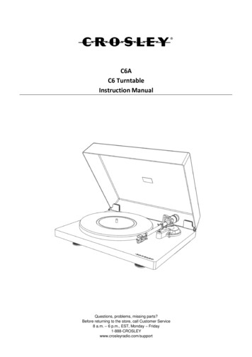
Certification Link ModelsMPTL (Modular PlugTerminated Link) configurationIncluded in the test: Connection between thePermanent link adapter plugand the MPTL socketConnection between MPTL plugand patch cord adapterNot included in the test: Permanent link adapter cordPermanent Link configurationIncluded in the test: Connection between thepermanent link adapter plugand the permanent link wiringNot included in the test: Permanent link adapter cordChannel ConfigurationIncluded in the test: The patch cord wireConnection between RJ45 plugand permanent link wiringNot included in the test: Connections between the 2patch cords plug and channeladapters6 www.trend-networks.com
Certification Link ModelsThe typical method is the Permanent Link to certify the infrastructure fixedwiring consisting of two female RJ45 sockets at each end and an optionalconsolidation point connector near the work area.The Channel method has the advantage of also certifying the two patch cordsconnected to the permanent link thus measuring the entire channel from endto end. The downside is that if the patch cords are changed, the channel mustbe re-certified.The MPTL method makes it possible to certify a hybrid link consisting of aconventional female socket at one side and a male connector (plug) at theother side. MPTL’s are used to directly connect to a PoE camera, Wi-Fi accesspoint, access control and other devices that are installed in fixed locations. Tocertify an MPTL a Permanent link adapter is attached to the main handset anda patch cord adapter on the remote handset. The patch cord adapter must beof the same category rating as the components of the MPTL.Modular PlugTerminatedLinkPermanent LinkChannelDirect AttachChannelDevice Link5e / 6 / 6APatch Cord&End-to-End LinkDepend On Us7
TREND AnyWARE CloudWith TREND AnyWARE Cloud, you no longer have to download and installtest management software to a PC.Create an account at https://anyware.trend-networks.comPlease use: Google Chrome, Microsoft Edge, or Mozilla Firefox.TREND AnyWARE CLOUD allows management of projects using LanTEK IVcertifiers.1. Who has the certifier2. Date of last software update3. Calibration date4. When the results were last eldTechnicianon www.trend-networks.com
TREND AnyWARE CloudPlease register your LanTEK IV to receive updated information at:https://www.trend-networks.comAn account is required to download software and documentation.Link LanTEK IV to your AnyWARE account.Select the Navigation menu:Select "Device", add your LanTEK IV withon the menu at the top right.Enter the identifier of your LanTEK IV via theentry screen.Depend On Us9
TREND AnyWARE CloudYou will find the Device ID in"Settings"on the LanTEK IV.10 www.trend-networks.com
LanTEK IV configuration: Settings menuPress on the gear icon at the top right of the screen to open the SettingsmenuChoose user interface modeChoose languageConnect to Wi-Fi hotspotSet Reference: calibrate system forCat 8.2, RJ45 patch cord adaptersand fibre optic test cordsView calibration information / Copythe calibration certificate to a USBkey in PDF formatStart the tonegeneratorDevice model, software versions,serial number, MAC addressUpdate device softwarePress “SYNC” to import or export test files. Import transfers blank testfiles from a USB key or AnyWARE Cloud to the LanTEK. Export transferscompleted test results to a USB key or AnyWARE Cloud.Press Accept after choosing an option.Depend On Us11
Default Autotest SettingsThis will save a standard configuration in the tester that will be the defaultsetting each time new tests are created, reducing setup time. The standardcan be changed when creating new tests as needed.Default Autotest parameters: definethe configuration for future testsSet date, time and units ofmeasureEnter operator nameVolume settingsScreen brightnessActivate remote control(Team Viewer)Show cursor when usingUSB mouse12 www.trend-networks.com
Wi-Fi SettingsTo connect LanTEK IV over Wi-Fi, tap SettingsSelect “Wi-Fi” - then activate it using the switch at the top right(green when active)Select a network and enter the password if requiredWi-Fi is then connected if thewave logo at the top right isnot crossed outMake sure that the signal strength is greater than 50%.Once connected, tap on the network name to view Wi-Fi details includingthe security settings, IP address and MAC address.On a site without a Wi-Fi network, use internet sharing with a mobile phonethat will be on a conventional mobile network.Once connected, tests can be uploaded/download to AnyWARE Cloud using“SYNC” from the home screen.Depend On Us13
Importing/Exporting jobsThe SYNC menu allows importing pre-configured jobs from AnyWARE Cloudor Desktop software to the LanTEK IV.Completed tests can be uploaded to AnyWARE Cloud when connected toWi-Fi. Jobs are synchronized between AnyWARE Cloud and the LanTEKIV. Tests added to a job on AnyWARE Cloud will be downloaded to LanTEKand tests created on LanTEK will be added to the corresponding job onAnyWARE Cloud.Alternatively, AnyWARE Desktop provides test management and reportingfrom a PC without using cloud services. Jobs created on AnyWARE Desktopcan be exported to a USB key and downloaded to LanTEK.Completed tests can be exported from LanTEK to a USB key then uploadedto AnyWARE Desktop and added to the corresponding job. Each test resultis saved with a file whose extension is .res (result).USB keys up to 512GB are supported and must be formatted as FAT32.SelectSYNCDownload imports jobs intothe LanTEK for testing.Upload sends completed testsfor viewing/reporting withTREND AnyWARE.Note: the Memory Stick optionis visible only when a USB keyis connected to the LanTEK.14 www.trend-networks.com
User Interface Operating ModesLanTEK IV version 1.50 software adds a new user interface mode that allowstesting without the need to create a job with pre-configured tests.The new mode is called “Standard” and the existing mode is called “Advanced”.Ensure the installed software is version1.50 or higherThe installed software version is displayedon the information screen while booting.Select the desired operation mode in thePreferences menu.Open the Preferences menuPress the gear icon to open the Preferencesmenu.Open Operation Mode selectionPress Operation Mode to reveal the modeselection screen.The currently selected Operation Mode isshown in small font.Choose desired modeStandard simplified mode that allowssetting name and specifications for eachindividual test.Advanced mode that allows preconfiguration of jobs with names andspecifications prior to testing.Depend On Us15
Standard User Interface OperationTesting with Standard mode requires setting four parameters before a test canbe started.All parameters can be set from the Home screen and each Autotest will be runwith the same parameters as the previous test. The last character of the testname is incremented by one digit (either letter or number).Previous Test - Name, type and result ofthe test that was previously performed.Touch the test name to open the resultspage.Next Test - Name of the next test to berun. The last character increments witheach test. The test name can be changedby touching the name.Touch Test or press the Autotest key toperform a test.SettingsJob - Name of the folder where the nexttest will be stored.Touch the “search” icon to create or selecta different job.Test standard - Summary of the test limitand cable type that will be used for thenext test. Touch the box to change thetest standard settings.Operator name - Name of user that isstored with each test.Touch the user icon to change theoperator name or add a new one.16 www.trend-networks.com
Next TestThe name of the next test to run is entered into the Next Test field. The namewill automatically increment the last character following each test.Press Test to perform a test and save it asID “A-08”.The Test icon turns grey when a test isrunning.The status bar increases to show the testprogress.Test A-08 is saved and is now in thePrevious Test section.Next Test is incremented to A-09 and isready for testing as indicated by the blueTest icon.Depend On Us17
Edit Next TestChange the Next Test name by touching the name and use the keyboard toenter the desired name.Type the desired name for the next test toperform and press the Enter key to accept.Press Enter when finished editing the testname.18 www.trend-networks.com
Job SelectionA new or existing Job can be selected for test storage.Press the search icon to open the Jobsscreen. to perform a test and save it as ID“A-08”.The currently selected Job is highlightedin blue.Touch the back arrow when the desiredjob is selected.Touch the name of an existing Job to makeit active. The line will turn blue to indicatethe selectionPrevious Test is blank because there are notests in the active Job.The default test name is Port01, touch thename to edit.Job B1-R5 is now active.Depend On Us19
Creating a new jobPress to create a new job.Press the tick when finished entering thenew name.Enter the name of the new job.20 www.trend-networks.com
Selecting test standardsTest limits and cable type are changed by touching the Test Standards box.Touch the Test Standard box to open thesettings.Select the required settings and press thetick when finished.Depend On Us21
Selecting the Operator nameThe operator name is can be selected from a list of previously entered namesor a new name can be added to the list. The operator name is included withthe test result and appears on printed certification reports.Touch the operator icon to change thename of the current operator.Choose a different operator name or press to enter the name of a new operator.22 www.trend-networks.com
Live wiremapLive wiremap displays a real-time wiremap diagram without the need torun a full Autotest. This can be launched in two ways: as an optional displayin the home screen test list, or directly from the pull-down menu from anyscreen.To activate Live wiremapdirectly: slide your finger downfrom the top edge of thescreen to reveal the shortcutmenu. Live wiremap is shownat the bottom half of thedisplay.To activate Live wiremap fromthe home screen tap optionsto open the selection menu.Choose Live wiremap toenable the function.Use the home screen optionsmenu to deselect Live wiremapwhen desired.Depend On Us23
Creating test filesNote: most items in a list have secondary options that can be viewed by long-pressing the item,similar to the right-click function of a mouse.The home screen shows the active job,the test that was previously run, and alist of remaining scheduled tests in thejob.A job named “Job 1” is the default jobin a new LanTEK IV.The operating workflow consists ofcreating a job for a customer, project,building, etc.Then test files with unique ID’s areadded to jobs with the performancestandard to be tested.This system allows quick testingof numerous tests with minimalconfiguration.Press JOBS to open the list of availablejob folders.Press the button to create a new job.24 www.trend-networks.com
Creating test filesEnter the name of the new job usingthe touch keyboard; In this example,the name is "Building 1".Confirm with the check mark at thetop-right of the screen.Optional test identifiers (building, floor,room, rack, panel, etc.) can be addedto each test ID to provide more details.ANSI/TIA-606 mode follows thenaming convention defined by the TIA606 standard.The Custom mode allows identifiersthat describe the location of the cableunder test.Depend On Us25
Creating test filesAdd a tick mark next to the desiredidentifier categories.Several predefined options exist foreach element of the identifiersTap the drop-down menu next toeach ID to choose an identifier.26 www.trend-networks.com
Creating test filesPress the check mark to save theconfiguration.The list is updated with the new jobcalled “Building 1”.The next step is to open the job folderand prepare it by adding tests.Press the name of the desired folder toopen it.Depend On Us27
Creating test filesThe Building 1 folder is open - tests cannow be added, deleted, or edited.Press to add new test files.The first step is to select a type ofmeasurement: Copper or Fiber optic.Press Copper to continue.28 www.trend-networks.com
Creating test filesTest IDs consist of a prefix (fixed name- for example “Cable”) and a range ofnumbers (example “1 to 48”)The prefix is the same for all futurenames created. Alphanumeric andspecial characters are allowed; whilethe "/" and "\" characters are notallowed. A space or dash after thename can be added as a separator,example “Cable-01”The start and end range define thestart and end limits of the counter.The numbers will be automaticallyincremented; in the previous examplethis will create Cable-01 to Cable-24.This range is alphanumeric and nospecial characters are allowed. Thenumber of characters in the start andend fields must be the same.In another example, the range is from01A to 12D. Test names will be createdas 02ACable-02B.Cable-12DAutomatic incrementing supportsalmost all combinations of numbersand letters.Press the “Test standard” box tocontinue the configuration.Depend On Us29
Creating test filesChoose the desired test standardfamily.In this example select:ISO/IEC 11801-1: 2017 A1/2Select the certification method.Permanent link is the most commonand certifies from patch panel to workarea outlet. Cable terminated withfemale connectors at both ends.In Channel certification, two patchcords (equipment room and workarea) are added. This is morecomplete since it also takes intoaccount the quality of the cords inaddition to the horizontal link.Channel adapters are required andthe patch cords used for certificationmust remain in place after each test.30 www.trend-networks.com
Creating test filesChoose the performance class forcertification.In this ISO example, Class EA certifiescabling up to 500 MHz for Ethernetapplications up to 10 Gigabit.In ISO / IEC there are different subfamilies of link models within the EAClass. PL1 PL2 CP1 is a typical Permanentfemale / female link PL3 is a Permanent link withthe addition consolidation pointconnection.Depend On Us31
Creating test filesThe MAX limit options test thesame links with additional optionalmeasurements carried out: TCL,ELTCTL, and DC resistance unbalance(DCRU).LanTEK IVs always measure theseparameters up to 500MHz and theresults are displayed as informativewith an “i” indicator instead of PASS/FAIL.If the MAX test is selected then thesemeasurements are marked PASS/FAILaccording to the limits defined by theselected test standard.Select Class EA PL1 PL2 CP1.The Cable Type selection is intendedto provide more detail on the natureof the components installed: thecable category, shield type, NVPand optionally the brand and model.The brand of the connectors may bedefined if desired.The options chosen here do notaffect the test limits or performancemeasurements, the only exceptionbeing the length measurement.Press the cable search icon to choosefrom the list of manufacturers of onboard cabling systems.32 www.trend-networks.com
Creating test filesA specific brand and model can thenbe selected - or choose “Generic” if aspecific brand is not desired.The name of the selected cable willappear on the certification report.Choosing a brand and modelautomatically sets the NVP (nominalvelocity of propagation) as defined bythe manufacturer.NVP is important for correctlymeasuring the length of a link; it onlyaffects this measurement and noothers.When the “Generic” is selected, theNVP can be manually entered orcalculated using a cable link of knownlength.The connector brand is optional andwill appear on the report. A list ofbrands is available by pressing thesearch icon.In this example, a “Generic” cableis selected and the NVP will bedetermined by measuring a knownlength of cable.Press “Measure NVP” to begin themeasurement process.Depend On Us33
Creating test filesConnect a link of 20 meters / 65 feetminimum between the two LanTEK IVhandsets.Enter the length of the link includingany test cords.In this test, the link is 24 meters plusthe 2 permanent link adapters of 2meters each, for a total of 28 meters.Enter 28 into the length field. Note,the units are set to meters or feetdepending on the units set in thetester preferences.Press the blue “Measure NVP” buttonto continue.The calculated NVP will be displayed,here it is 77%.Press the check mark to confirm andcontinue.34 www.trend-networks.com
Creating test filesReview the configuration parametersand press the check mark to continue.If all parameters are correct, press thecheck mark to confirm and create thelist of tests.Press the home buttonthe home screen.to return toDepend On Us35
Creating test filesHere, the home screen with the newjob and test ID’s is shown.The “Test” icon will turn blue whenthe main and remote handsets areconnected to a link. If the icon remainsgray it means that there is a problem:remote off, testers not connected tothe same link or the link is broken.The LanTEK IV handsets are able tocommunicate if at least two (2) wiresin the cable have continuity. Even whenthe two wires are not of the same pairwithin the cable.36 www.trend-networks.com
Presentation of testsThe colors of the test icon and thevertical bar to the left of the nameindicate the status of each test inthe folder.In addition, the blue color of theTest icon and the circle symbolindicate that the two handsets arecorrectly connected and ready totest.Circle: not testedBlue bar not testedIf the buttons are gray it means thatthe two handsets are not connectedcorrectly and an Autotest cannot bestarted.Gray button: handsets notconnectedCircle: not testedBlue bar not testedDepend On Us37
Presentation of testsColored test buttons:Main and remote handsets areconnected and ready to testGreen bar / green box PassRed bar / red box FailOrange bar / orange box: marginalPass/FailGrey test buttons:Main and remote handsets are notconnected and an Autotest cannot bestartedGreen bar / green box passRed bar / red box failureOrange bar / orange box: marginalPass/Fail38 www.trend-networks.com
Performing testsAn Autotest can start only if the twohandsets are correctly connected tothe same link to be tested.Ready to test indicators:1.2.On-screen test buttons are blueThe Autotest icon is displayed3.4.A musical melody is heardThe link symbol at the top of thehandset lights up blueVisiLINQ Permanent Linkadapters light up blue5.Depend On Us39
Performing testsOptions to perform an Autotest:1. Press the Autotest key on eachhandset2. Press the blue Test button on thescreen3. Press the black circular button onthe end of the VisiLINQ adapterA blue progress bar is displayed whilethe test is running.40 www.trend-networks.com
Display of test resultsInformation on the details and marginsof the test measurements is availableon the list of tests for completedAutotests.Press the button to open theoptions on the Home screen.Select an option to display the desiredmeasurement related to the testnumber.When activated, the margin ofthe selected measurement willbe displayed for each completedAutotest.Press the name of the test to openthe measurement results screen.Depend On Us41
Display of test resultsPress “View Low Frequency results” todisplay the measurements not presenton the first page.The measurements appear with therepresentation of the main or remotehandset to indicate which side the linkhas the worst value or fault.Scroll down to see the full list on thefirst page.The wiremap is always at the topof the list because it is a commonfailure mode, unless there is a failedmeasurement.You can re-run the test or edit it(to rename it for example) with thebuttons at the bottom of the screen.Tap a measurement from the summaryscreen to open the detailed view of theresults.Switch between graphical or tabularview.Graphic display options.Switch between main and receiverhandset viewSelect the pairs to display on the plot.42 www.trend-networks.com
Display of test resultsTap any point on the plot to displaythe frequency, the measured value andthe associated limit.Slide your finger across a range toenlarge the view.Depend On Us43
Display of test resultsAn enlarged view of the plot allows adetailed analysis.Zoom out for normal view.Switch between scroll and zoomfunctions. In scroll mode swiping thescreen will slide the view of the graphwhile maintaining the current zoomlevel.Switch to the tabular view of the data.44 www.trend-networks.com
Display of test resultsThe tabular view of the measurementsdisplays the lowest margin, and thefrequency point where the measuredvalue is closest to the test limit.Press return to return to the testsummary screen.Press View Low Frequency resultsresults to display the secondpage with low frequency/DCmeasurements.Depend On Us45
Display of test resultsPresentation of the measurements onthe second page.The "i" symbol indicates that thismeasurement is either optional ormeets certain criteria where a pass /fail result is not required.46 www.trend-networks.com
Test list optionsThe list of tests can be customized to display the margin values for several keymetrics, which provides additional information at a glance.The filter function modifies the test IDs that appear to streamline operationson large projects.Open a job to view the list of tests.By default the test standard used isdisplayed under each identifier - andall the tests in the job are listed onebelow the other.Press the Options button to changethe information displayed on thesecond line of each test.Select the desiredmeasurement to display inthe list of tests.Depend On Us47
Live wiremapSelect Live wiremap to display a realtime measurement of cable continuity.Live wiremap allows a check ofcontinuity before performing theAutotest.With Live wiremap active the upperoptions button changes the wiremapcolor code display.The lower options button deactivatesthe Wiring Diagram or modifies thevalue displayed on the second line ofthe name of each test.48 www.trend-networks.com
Filtering display of test resultsPress the filter button to display onlythe desired tests in the current folder.It is possible with the three buttons atthe top of the screen to filter the teststhat you want to display: Untested,Passed, or Failed results.The tests in the folder will be filteredif the corresponding status box iscolored. If you press one of the buttonsthe icon turns gray and hides testresults matching that status.For example, pressing Passed changesthe button from green to gray, whichmeans that passed tests will be hidden,while failed and unmeasured tests willbe displayed when the filter is applied.Press Apply Filters to confirm thechoices - or Clear Filters to deactivatefiltering and display all tests.Depend On Us49
Filtering display of test resultsThe other filter tools allow sortingaccording to the test standard, and/orthe prefix of the test name, and/or thetest identifiers as desired.Multiple filters can be selected tonarrow the tests displayed in the homescreen.In this example Panel 02 is selectedand only the test ID’s for Panel 02 willbe displayed.Press Apply Filters to confirm theselection.The list of sorted tests dedicated onlyto Panel 02 will be presented.Return to the Filter screen and tapClear Filters to remove them and viewall tests again.50 www.trend-networks.com
Jobs management and synchronizationManage JobsPress JOBS to view the list jobs.Sort the list of jobs alphabetically.Sort jobs by creation date.Select multiple jobs.Create a new job.Depend On Us51
Job management and synchronizationLong-press a job to open the optionsmenu.The active job cannot be deleted. Todelete the active job, first long-pressthe name of a different job to open theoptions menu.Press Set as current job to make it theactive job.Then long-press the job to be deleted.The options menu including the optionto delete the folder and all test resultsis now available.Please note that job deletion ispermanent and cannot be canceled, allincluded tests will be lost.When a folder has been synced to thecloud or to a USB drive, it cannot besynced again without clearing the syncstatus.Tap Clear sync status in the foldersoptions to allow the folder to syncagain. This may be necessary when afolder has been synchronized with thecloud and another copy is desired on aUSB stick.52 www.trend-networks.com
Job management and synchronizationFile synchronizationFolders can be synchro
Please use: Google Chrome, Microsoft Edge, or Mozilla Firefox. TREND AnyWARE CLOUD allows management of projects using LanTEK IV certifiers. 1. Who has the certifier 2. Date of last software update 3. Calibration date 4. When the results were last synchronized Field Technician on the jobsite Project Manager Cable Manufacturer TREND Networks .