Transcription
2009 EditionPage 347PART 3MARKINGSCHAPTER 3A. GENERALSection 3A.01 Functions and LimitationsSupport:01Markings on highways and on private roads open to public travel have important functions in providingguidance and information for the road user. Major marking types include pavement and curb markings,delineators, colored pavements, channelizing devices, and islands. In some cases, markings are used tosupplement other traffic control devices such as signs, signals, and other markings. In other instances, markingsare used alone to effectively convey regulations, guidance, or warnings in ways not obtainable by the use ofother devices.02Markings have limitations. Visibility of the markings can be limited by snow, debris, and water on or adjacentto the markings. Marking durability is affected by material characteristics, traffic volumes, weather, and location.However, under most highway conditions, markings provide important information while allowing minimaldiversion of attention from the roadway.Section 3A.02 Standardization of ApplicationStandard:01Each standard marking shall be used only to convey the meaning prescribed for that marking in thisManual. When used for applications not described in this Manual, markings shall conform in all respectsto the principles and standards set forth in this Manual.Guidance:02Before any new highway, private road open to public travel (see definition in Section 1A.13), paved detour, ortemporary route is opened to public travel, all necessary markings should be in place.Standard:03Markings that must be visible at night shall be retroreflective unless ambient illumination assures thatthe markings are adequately visible. All markings on Interstate highways shall be retroreflective.04Markings that are no longer applicable for roadway conditions or restrictions and that might causeconfusion for the road user shall be removed or obliterated to be unidentifiable as a marking as soonas practical.Option:05Until they can be removed or obliterated, markings may be temporarily masked with tape that isapproximately the same color as the pavement.Section 3A.03 Maintaining Minimum Pavement Marking Retroreflectivity(This Section is reserved for future text based on FHWA rulemaking.)Section 3A.04 MaterialsSupport:01Pavement and curb markings are commonly placed by using paints or thermoplastics; however, other suitablemarking materials, including raised pavement markers and colored pavements, are also used. Delineators andchannelizing devices are visibly placed in a vertical position similar to signs above the roadway.02Some marking systems consist of clumps or droplets of material with visible open spaces of bare pavementbetween the material droplets. These marking systems can function in a manner that is similar to the markingsystems that completely cover the pavement surface and are suitable for use as pavement markings if they meet theother pavement marking requirements of the highway agency.Guidance:03The materials used for markings should provide the specified color throughout their useful life.04Consideration should be given to selecting pavement marking materials that will minimize tripping or loss oftraction for road users, including pedestrians, bicyclists, and motorcyclists.05Delineators should not present a vertical or horizontal clearance obstacle for pedestrians.December 2009 Sect. 3A.01 to 3A.04
Page 3482009 EditionSection 3A.05 ColorsStandard:01Markings shall be yellow, white, red, blue, or purple. The colors for markings shall conform to thestandard highway colors. Black in conjunction with one of the colors mentioned in the first sentence of thisparagraph shall be a usable color.02When used, white markings for longitudinal lines shall delineate:A. The separation of traffic flows in the same direction, orB. The right-hand edge of the roadway.03When used, yellow markings for longitudinal lines shall delineate:A. The separation of traffic traveling in opposite directions,B. The left-hand edge of the roadways of divided highways and one-way streets or ramps, orC. The separation of two-way left-turn lanes and reversible lanes from other lanes.04When used, red raised pavement markers or delineators shall delineate:A. Truck escape ramps, orB. One-way roadways, ramps, or travel lanes that shall not be entered or used in the direction fromwhich the markers are visible.05When used, blue markings shall supplement white markings for parking spaces for personswith disabilities.06When used, purple markings shall supplement lane line or edge line markings for toll plaza approachlanes that are restricted to use only by vehicles with registered electronic toll collection accounts.Option:07Colors used for official route shield signs (see Section 2D.11) may be used as colors of symbol markings tosimulate route shields on the pavement (see Section 3B.20.)08Black may be used in combination with the colors mentioned in the first sentence of Paragraph 1 where alight-colored pavement does not provide sufficient contrast with the markings.Support:09When used in combination with other colors, black is not considered a marking color, but only acontrast-enhancing system for the markings.Section 3A.06 Functions, Widths, and Patterns of Longitudinal Pavement MarkingsStandard:The general functions of longitudinal lines shall be:A. A double line indicates maximum or special restrictions,B. A solid line discourages or prohibits crossing (depending on the specific application),C. A broken line indicates a permissive condition, andD. A dotted line provides guidance or warning of a downstream change in lane function.02The widths and patterns of longitudinal lines shall be as follows:A. Normal line—4 to 6 inches wide.B. Wide line—at least twice the width of a normal line.C. Double line—two parallel lines separated by a discernible space.D. Broken line—normal line segments separated by gaps.E. Dotted line—noticeably shorter line segments separated by shorter gaps than used for a brokenline. The width of a dotted line extension shall be at least the same as the width of the lineit extends.Support:03The width of the line indicates the degree of emphasis.Guidance:04Broken lines should consist of 10-foot line segments and 30-foot gaps, or dimensions in a similar ratio of linesegments to gaps as appropriate for traffic speeds and need for delineation.Support:05Patterns for dotted lines depend on the application (see Sections 3B.04 and 3B.08.)Guidance:06A dotted line for line extensions within an intersection or taper area should consist of 2-foot line segmentsand 2- to 6-foot gaps. A dotted line used as a lane line should consist of 3-foot line segments and 9-foot gaps.01Sect. 3A.05 to 3A.06 December 2009
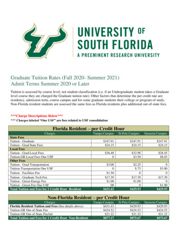
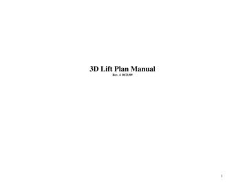
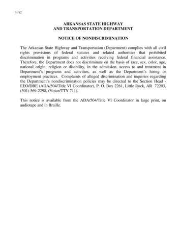
2009 EditionPage 349CHAPTER 3B. PAVEMENT AND CURB MARKINGSSection 3B.01 Yellow Center Line Pavement Markings and WarrantsStandard:01Center line pavement markings, when used, shall be the pavement markings used to delineate theseparation of traffic lanes that have opposite directions of travel on a roadway and shall be yellow.Option:02Center line pavement markings may be placed at a location that is not the geometric center of the roadway.03On roadways without continuous center line pavement markings, short sections may be marked with centerline pavement markings to control the position of traffic at specific locations, such as around curves, over hills, onapproaches to grade crossings, at grade crossings, and at bridges.Standard:04The center line markings on two-lane, two-way roadways shall be one of the following as shown inFigure 3B-1:A. Two-direction passing zone markings consisting of a normal broken yellow line where crossing thecenter line markings for passing with care is permitted for traffic traveling in either direction;B. One-direction no-passing zone markings consisting of a double yellow line, one of which is anormal broken yellow line and the other is a normal solid yellow line, where crossing the center linemarkings for passing with care is permitted for the traffic traveling adjacent to the broken line, butis prohibited for traffic traveling adjacent to the solid line; orC. Two-direction no-passing zone markings consisting of two normal solid yellow lines where crossingthe center line markings for passing is prohibited for traffic traveling in either direction.05A single solid yellow line shall not be used as a center line marking on a two-way roadway.06The center line markings on undivided two-way roadways with four or more lanes for moving motorvehicle traffic always available shall be the two-direction no-passing zone markings consisting of a soliddouble yellow line as shown in Figure 3B-2.Guidance:07On two-way roadways with three through lanes for moving motor vehicle traffic, two lanes should bedesignated for traffic in one direction by using one- or two-direction no-passing zone markings as shown inFigure 3B-3.Support:08Sections 11-301(c) and 11-311(c) of the “Uniform Vehicle Code (UVC)” contain information regarding leftturns across center line no-passing zone markings and paved medians, respectively. The UVC can be obtainedfrom the National Committee on Uniform Traffic Laws and Ordinances at the address shown on Page i.Standard:09Center line markings shall be placed on all paved urban arterials and collectors that have a traveledway of 20 feet or more in width and an ADT of 6,000 vehicles per day or greater. Center line markingsshall also be placed on all paved two-way streets or highways that have three or more lanes for movingmotor vehicle traffic.Guidance:10Center line markings should be placed on paved urban arterials and collectors that have a traveled way of20 feet or more in width and an ADT of 4,000 vehicles per day or greater. Center line markings should also beplaced on all rural arterials and collectors that have a traveled way of 18 feet or more in width and an ADT of3,000 vehicles per day or greater. Center line markings should also be placed on other traveled ways where anengineering study indicates such a need.11Engineering judgment should be used in determining whether to place center line markings on traveled waysthat are less than 16 feet wide because of the potential for traffic encroaching on the pavement edges, trafficbeing affected by parked vehicles, and traffic encroaching into the opposing traffic lane.Option:12Center line markings may be placed on other paved two-way traveled ways that are 16 feet or more in width.13If a traffic count is not available, the ADTs described in this Section may be estimates that are based onengineering judgment.December 2009 Sect. 3B.01
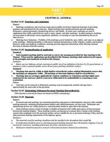
Page 3502009 EditionFigure 3B-1. Examples of Two-Lane, Two-Way Marking ApplicationsA - Typical two-lane, two-way markingwith passing permitted in both directionsB - Typical two-lane, two-way markingwith no-passing zonesLegendDirection of travelNopassingzoneNopassingzoneSect. 3B.01 December 2009
2009 EditionPage 351Figure 3B-2. Examples of Four-or-More Lane, Two-Way Marking ApplicationsA - Typical multi-lane,two-way markingB - Typical multi-lane, two-way markingwith single lane left turn channelizationLegendOptional in someconditions (seeSection 3B.20)Direction of travelOptional yellow diagonalcrosshatch markingsOptional dottedextensionOptional dottedextensionDecember 2009 Sect. 3B.01
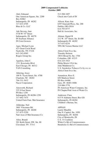
Page 3522009 EditionFigure 3B-3. Examples of Three-Lane, Two-Way Marking ApplicationsA - Typical three-lane, two-way marking withpassing permitted in single-lane directionLegendDirection of travelB - Typical three-lane, two-way marking withpassing prohibited in single-lane directionSection 3B.02 No-Passing Zone Pavement Markings and WarrantsStandard:01No-passing zones shall be marked by either the one direction no-passing zone pavement markings orthe two-direction no-passing zone pavement markings described in Section 3B.01 and shown in Figures3B-1 and 3B-3.02When center line markings are used, no-passing zone markings shall be used on two-way roadways atlane-reduction transitions (see Section 3B.09) and on approaches to obstructions that must be passed on theright (see Section 3B.10).03On two-way, two- or three-lane roadways where center line markings are installed, no-passing zonesshall be established at vertical and horizontal curves and other locations where an engineering studyindicates that passing must be prohibited because of inadequate sight distances or other special conditions.04On roadways with center line markings, no-passing zone markings shall be used at horizontal orvertical curves where the passing sight distance is less than the minimum shown in Table 3B-1 for the85th-percentile speed or the posted or statutory speed limit. The passing sight distance on a vertical curve isthe distance at which an object 3.5 feet above the pavement surface can be seen from a point 3.5 feet abovethe pavement (see Figure 3B-4). Similarly, the passing sight distance on a horizontal curve is the distancemeasured along the center line (or right-hand lane line of a three-lane roadway) between two points 3.5feet above the pavement on a line tangent to theembankment or other obstruction that cuts off theTable 3B-1. Minimum Passing Sightview on the inside of the curve (see Figure 3B-4).Distancesfor No-Passing Zone MarkingsSupport:05The upstream end of a no-passing zone at point “a”85th-Percentile or Posted orMinimum Passingin Figure 3B-4 is that point where the sight distanceStatutory Speed LimitSight Distancefirst becomes less than that specified in Table 3B-1.25 mph450 feetThe downstream end of the no-passing zone at point30 mph500 feet“b” in Figure 3B-4 is that point at which the sight35mph550 feetdistance again becomes greater than the minimum40 mph600 feetspecified.45 mph700 feet06The values of the minimum passing sight distancesthat are shown in Table 3B-1 are for operational use50 mph800 feetin marking no-passing zones and are less than the55 mph900 feetvalues that are suggested for geometric design by the60 mph1,000 feetAASHTO Policy on Geometric Design of Streets and65 mph1,100 feetHighways (see Section 1A.11).70 mphSect. 3B.02 1,200 feetDecember 2009
2009 EditionPage 353Figure 3B-4. Method of Locating and Determining the Limits ofNo-Passing Zones at CurvesLegendDirection of travelA - No-passing zone at VERTICAL CURVEhtsig le,ng centi disrspa h-pe speemtyimu for 85 tutorniM ce r stanoat,dis stedleporofightnt pf sieomeeLinPavMdis inimtaupos nce m pated for 8 ssin, org5sta th-pe sighttuto rcery s ntilepee ,PavLindemeoentfprosigfilehtNo-pa(in ssindire g zctio onen in , a'dic to bated) '3.5 ftb'bto be, a ted)noz dicangssi n in-pa rectiooN di(in3.5 fta, a' Begin no-passing zoneb, b' End no-passing zoneSight distance becomes less thanminimum measured between points3.5 feet above pavementSight distance again exceeds minimum3.5 ftProfile ViewNote: No-passing zones in opposite directions may or may not overlap,depending on alignmentB - No-passing zone at HORIZONTAL CURVEight,ing spass ercentilemupMinim for 85th- ry speedetoncdista d, or statuposteMinimumpassing sidistanceghtforposted, or 85th-percentile,statutoryspeedLines of sightb'baNop(in assingdirectio zone,n inadica ' to b'ted)oba t d),ne atezo ndicgiinss ionpa irectNo in d(a'a, a' Begin no-passing zoneb, b' End no-passing zoneSight distance becomes less thanminimum measured between points3.5 feet above pavementSight distance again exceeds minimumPlan ViewNote: No-passing zones in opposite directions may or may not overlap,depending on alignmentDecember 2009 Sect. 3B.02
Page 3542009 EditionGuidance:07Where the distance between successive no-passing zones is less than 400 feet, no-passing markings shouldconnect the zones.Standard:08Where center line markings are used, no-passing zone markings shall be used on approaches to gradecrossings in compliance with Section 8B.27.Option:09In addition to pavement markings, no-passing zone signs (see Sections 2B.28, 2B.29, and 2C.45) may be usedto emphasize the existence and extent of a no-passing zone.Support:10Section 11-307 of the “Uniform Vehicle Code (UVC)” contains further information regarding required roaduser behavior in no-passing zones. The UVC can be obtained from the National Committee on Uniform TrafficLaws and Ordinances at the address shown on Page i.Standard:11On three-lane roadways where the direction of travel in the center lane transitions from one directionto the other, a no-passing buffer zone shall be provided in the center lane as shown in Figure 3B-5.A lane-reduction transition (see Section 3B.09) shall be provided at each end of the buffer zone.12The buffer zone shall be a flush median island formed by two sets of double yellow center linemarkings that is at least 50 feet in length.Option:13Yellow diagonal crosshatch markings (see Section 3B.24) may be placed in the flush median area between thetwo sets of no-passing zone markings as shown in Figure 3B-5.Guidance:14For three-lane roadways having a posted or statutory speed limit of 45 mph or greater, the lane transitiontaper length should be computed by the formula L WS. For roadways where the posted or statutory speed limitis less than 45 mph, the formula L WS2/60 should be used to compute the taper length.Support:15Under both formulas, L equals the taper length in feet, W equals the width of the center lane or offset distancein feet, and S equals the 85th-percentile speed or the posted or statutory speed limit, whichever is higher.Guidance:16The minimum lane transition taper length should be 100 feet in urban areas and 200 feet in rural areas.Section 3B.03 Other Yellow Longitudinal Pavement MarkingsStandard:If reversible lanes are used, the lane line pavement markings on each side of reversible lanes shallconsist of a normal broken double yellow line to delineate the edge of a lane in which the direction of travelis reversed from time to time, such that each of these markings serve as the center line markings of theroadway during some period (see Figure 3B-6).02Signs (see Section 2B.26), lane-use control signals (see Chapter 4M), or both shall be used to supplementreversible lane pavement markings.03If a two-way left-turn lane that is never operated as a reversible lane is used, the lane line pavementmarkings on each side of the two-way left-turn lane shall consist of a normal broken yellow line and anormal solid yellow line to delineate the edges of a lane that can be used by traffic in either direction as partof a left-turn maneuver. These markings shall be placed with the broken line toward the two-way left-turnlane and the solid line toward the adjacent traffic lane as shown in Figure 3B-7.Guidance:04White two-way left-turn lane-use arrows (see Figure 3B-7), should be used in conjunction with thelongitudinal two-way left-turn markings at the locations described in Section 3B.20.05Signs should be used in conjunction with the two-way left turn markings (see Section 2B.24).Standard:06If a continuous flush median island formed by pavement markings separating travel in oppositedirections is used, two sets of solid double yellow lines shall be used to form the island as shown in Figures3B-2 and 3B-5. Other markings in the median island area shall also be yellow, except crosswalk markingswhich shall be white (see Section 3B.18).01Sect. 3B.02 to 3B.03 December 2009
2009 EditionPage 355Figure 3B-5. Example of Application of Three-Lane, Two-Way Marking forChanging Direction of the Center LaneLegendDirection of travelNotes:1. See Section 3B.02 for determining theminimum length of the buffer zone2. Lane-reduction arrows are optional forspeeds of 40 mph or less3. See Figure 3B-14 for lane-reductiontransition markings and determinationof taper length LTwo directional nopassing markingZone of limitedsight distance,Car “Y”Car “Y”BufferzoneCar “X”Zone of limitedsight distance,Car “X”Optional yellow diagonalcrosshatch markingsTwo directional nopassing markingDecember 2009 (see Note 3)Sect. 3B.03
Page 3562009 EditionFigure 3B-6. Example of Reversible Lane Marking ApplicationLegendDirection of travelorSection 3B.04 White Lane Line Pavement Markings and WarrantsStandard:When used, lane line pavement markings delineating the separation of traffic lanes that have the samedirection of travel shall be white.02Lane line markings shall be used on all freeways and Interstate highways.Guidance:03Lane line markings should be used on all roadways that are intended to operate with two or more adjacenttraffic lanes in the same direction of travel, except as otherwise required for reversible lanes. Lane line markingsshould also be used at congested locations where the roadway will accommodate more traffic lanes with lane linemarkings than without the markings.Support:04Examples of lane line markings are shown in Figures 3B-2, 3B-3, and 3B-7 through 3B-13.Standard:05Except as provided in Paragraph 6, where crossing the lane line markings with care is permitted, thelane line markings shall consist of a normal broken white line.06A dotted white line marking shall be used as the lane line to separate a through lane that continuesbeyond the interchange or intersection from an adjacent lane for any of the following conditions:A. A deceleration or acceleration lane,B. A through lane that becomes a mandatory exit or turn lane,C. An auxiliary lane 2 miles or less in length between an entrance ramp and an exit ramp, orD. An auxiliary lane 1 mile or less in length between two adjacent intersections.07For exit ramps with a parallel deceleration lane, a normal width dotted white lane line shall be installedfrom the upstream end of the full-width deceleration lane to the theoretical gore or to the upstream end of asolid white lane line, if used, that extends upstream from the theoretical gore as shown in Drawings A and Cof Figure 3B-8.Option:08For exit ramps with a parallel deceleration lane, a normal width dotted white line extension may be installed inthe taper area upstream from the full-width deceleration lane as shown in Drawings A and C of Figure 3B-8.09For an exit ramp with a tapered deceleration lane, a normal width dotted white line extension may be installedfrom the theoretical gore through the taper area such that it meets the edge line at the upstream end of the taper asshown in Drawing B of Figure 3B-8.Standard:10For entrance ramps with a parallel acceleration lane, a normal width dotted white lane line shall beinstalled from the theoretical gore or from the downstream end of a solid white lane line, if used, thatextends downstream from the theoretical gore, to a point at least one-half the distance from the theoreticalgore to the downstream end of the acceleration taper, as shown in Drawing A of Figure 3B-9.Option:11For entrance ramps with a parallel acceleration lane, a normal width dotted white line extension may beinstalled from the downstream end of the dotted white lane line to the downstream end of the acceleration taper, asshown in Drawing A of Figure 3B-9.12For entrance ramps with a tapered acceleration lane, a normal width dotted white line extension may beinstalled from the downstream end of the channelizing line adjacent to the through lane to the downstream end ofthe acceleration taper, as shown in Drawings B and C of Figure 3B-9.01Sect. 3B.04 December 2009
2009 EditionPage 357Figure 3B-7. Example of Two-Way Left-Turn Lane Marking ApplicationsLegendDirection of travelMINOR CROSS STREETNote: Single-direction left-turn arrowsshall not be used in lanes borderedon both sides by two-way left-turnlane markings.See Section 3B.20 for use of additionalarrows beyond the beginning of thetwo-way left-turn lane8 to 16 ftMAJOR CROSS STREETDecember 2009 Sect. 3B.04
Page 3582009 EditionFigure 3B-8. Examples of Dotted Line and Channelizing Line Applicationsfor Exit Ramp Markings (Sheet 1 of 2)A - Parallel deceleration laneB - Tapered deceleration lanePhysicalgoreOptionalwhite chevronmarkings inneutral areaWhitechannelizinglinesOptionalwhite chevronmarkingsin neutralareaTheoretical goreWide or normal widthsolid white lane line(optional, variablelength) or normalwidth dotted whitelane lineNormal width dottedwhite lane line fromupstream end of fullwidth decelerationlane to theoreticalgore or to upstreamend of optional solidwhite lane lineNormal width dottedlane line or dottedextension of righthand edge lineis optional indecelerationlane taperSect. 3B.04 PhysicalgoreWhitechannelizinglinesTheoretical goreOptionalnormal widthdotted whiteextension ofright-handedge lineLegendDirection of travelDecember 2009
2009 EditionPage 359Figure 3B-8. Examples of Dotted Line and Channelizing Line Applicationsfor Exit Ramp Markings (Sheet 2 of 2)C – Parallel deceleration lane at a multi-lane exit ramp having an optional exit lanethat also carries the through routePhysical goreWhite channelizing linesOptional whitechevron markingsin neutral areaNormal width or widesolid white lane lineNormal width or widesolid white lane line(variable length)Theoretical goreVariesNormal width dottedwhite lane line fromupstream end of fullwidth decelerationlane to theoreticalgore or to upstreamend of solid whitelane lineNormal width dottedlane line or dottedextension of righthand edge lineis optional indecelerationlane taperDecember 2009 LegendDirection of travelSect. 3B.04
Page 3602009 EditionFigure 3B-9. Examples of Dotted Line and Channelizing Line Applications forEntrance Ramp Markings (Sheet 1 of 2)A - Parallel acceleration laneB - Tapered acceleration laneLegendDirection of travelA Length of accelerationlane plus taperOptional normal widthdotted white lane lineor dotted extension ofright-hand edge linedownstream beyondthe “0.5 A MIN.” pointOptional normal width dottedextension of right-hand edge lineFull lane widthANormal width dottedwhite lane line for atleast half the length ofthe full-width accelerationlane plus taperTheoretical gore0.5 AMIN.Wide or normal widthsolid white lane line(optional, variablelength) or normal widthdotted white lane lineNeutral areaTheoretical goreWhitechannelizing linesOptional whitechevron markingsin neutral areaWhite channelizing linesPhysical goreEdge ofthroughlanePhysical goreSect. 3B.04 December 2009
2009 EditionPage 361Figure 3B-9. Examples of Dotted Line and Channelizing Line Applicationsfor Entrance Ramp Markings (Sheet 2 of 2)C - Tapered acceleration laneLegendDirection of travelB Distance from physical goreto downstream end of fullwidth acceleration laneOptional normal width dottedextension of right-hand edge lineFull lane widthTheoretical goreBNeutral areaWhite channelizing lines0.5 BMIN.Physical goreEdge ofthroughlaneDecember 2009 Sect. 3B.04
Page 3622009 EditionStandard:13A wide dotted white lane line shall be used:A. As a lane drop marking in advance of lane drops at exit ramps to distinguish a lane drop from anormal exit ramp (see Drawings A, B, and C of Figure 3B-10),B. In advance of freeway route splits with dedicated lanes (see Drawing D of Figure 3B-10),C. To separate a through lane that continues beyond an interchange from an adjacent auxiliary lanebetween an entrance ramp and an exit ramp (see Drawing E of Figure 3B-10),D. As a lane drop marking in advance of lane drops at intersections to distinguish a lane drop from anintersection through lane (see Drawing A of Figure 3B-11), andE. To separate a through lane that continues beyond an intersection from an adjacent auxiliary lanebetween two intersections (see Drawing B of Figure 3B-11).Guidance:14lane drop markings used in advance of lane drops at freeway and expressway exit ramps should begin atleast 1/2 mile in advance of the theoretical gore.15On the approach to a multi-lane exit ramp having an optional exit lane that also carries through traffic, laneline markings should be used as illustrated in Drawing B of Figure 3B-10. In this case, if the right-most exit laneis an added lane such as a parallel deceleration lane, the lane drop marking should begin at the upstream end ofthe full-width deceleration lane, as shown in Drawing C of Figure 3B-8.16lane drop markings used in advance of lane drops at intersections should begin a distance in advance of theintersection that is determined by engineering judgment as suitable to enable drivers who do not desire to makethe mandatory turn to move out of the lane being dropped prior to reaching the queue of vehicles that are waitingto make the turn. The lane drop marking should begin no closer to the intersection than the most upstreamregulatory or warning sign associated with the lane drop.17The dotted white lane lines that are used for lane drop markings and that are used as a lane lineseparating through lanes from auxiliary lanes should consist of line segments that are 3 feet in length separatedby 9-foot gaps.Support:18Section 3B.20 contains information regarding other markings that are associated with lane drops, such aslane-use arrow markings and ONLY word markings.19Section 3B.09 contains information about the lane line markings that are to be used for transition areas wherethe number of through lanes is reduced.Standard:20Where crossing the lane line markings is discouraged, the lane line markings shall consist of a normalor wide solid white line.Option:21Where it is intended to discourage lane changing on the approach to an exit ramp, a wide solid white lane linemay extend upstream from the theoretical gore or, for multi-lane exits, as shown in Drawing B of Figure 3B-10, fora distance that is determined by engineering judgment.22Where lane changes might cause conflicts, a wide or normal solid white lane line may extend upstream froman intersection.23In the case of a lane drop at an exit ramp or intersection, such a solid white line may replace a portion, but notall of the length of the wide dotted white lane line.Support:24Section 3B.09 contains information about the lane line markings that are to be used for transition areas wherethe number of through lanes is reduced.Guidance:25On approaches to inte
09 Center line markings shall be placed on all paved urban arterials and collectors that have a traveled way of 20 feet or more in width and an ADT of 6,000 vehicles per day or greater. Center line markings shall also be placed on all paved two-way streets or highways that have three or more lanes for moving motor vehicle traffic. Guidance: