Transcription
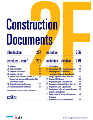
2FConstructionDocumentsintroductionactivities - core*254narrative256272activities - elective279Mock-UpsWindow InstallationComparison of DocumentsCompliance with ADAFeedback on the Usefulness, or Quality, ofDrawings from Contractors/Subcontractors WhoBuild Architect’s Design Checking & Coordinating Documents Construction Document Coordination *A maximum of 40 hours of core credit may be earned in this experience area.exhibits272273274275276277278 LEED Checklist Attending an In-Office Product Presentation Developing a LEED-Certified Project,Incorporating Sustainable Design Concepts Changes Required In Order to Meet Code Creation of CAD Standard Prepare a Consultant Coordination Plan Preparation of Traditional Redlined Check Set Preparation of Green-Light Check Set Development of a Tool for Preventive DocumentChecking and Coordination Critical Review of Checking and CoordinationProcedures Preparation of a Check Set Error Analysis279280281282283284285286287288289---- 2013 Emerging Professional’s Companion
Construction DocumentsIntroductionBy completing the activities in this chapter, you will gain an understandingof the activities involved in developing construction documents. Thefollowing information is taken from the NCARB IDP Guidelines:Construction DocumentsMinimum Construction Documents Experience: 1,200 HoursDefinition: Includes the written and graphic instructions used forconstruction of the project. These documents must be accurate, consistent,complete, and understandable.TasksAt the completion of your internship, you should be able to: Prepare construction documents Coordinate construction documents (e.g., architectural, structural,mechanical, civil, electrical) Conduct quality control review of project documents Apply sustainable design principles2F254Knowledge Of/Skill In 3-D modeling Adaptive reuse of buildings and/or materials Alternative energy systems and technologies Basic engineering principles Building design Building envelope Building Information Modeling (BIM) technology Building systems and their integration Characteristics and properties of construction materials Computer Aided Design and Drafting (CADD) Conflict resolution Constructability Construction details Construction sequencing Creativity and vision Critical thinking (e.g., analysis, synthesis, and evaluation ofinformation) Design impact on human behavior Design principles Designing and delivering presentations Engineering load calculations Freehand drawing and design sketching Furnishings, fixtures, and equipment Graphic communication Hazardous materials mitigation Implications of design decisions (e.g., cost, engineering, schedule) Indoor air quality Interior materials and finishes Interpersonal skills (e.g., listening, diplomacy, responsiveness)Emerging Professional’s Companion www.epcompanion.orgresourcesDownload the current InternDevelopment Program (IDP)guidelines at he American Institute ofArchitects. Demkin, Joseph A.,ed. The Architect’s Handbook ofProfessional Practice. 14th ed.Hoboken: John Wiley & Sons,2008. Chapter 12.3 ConstructionDocumentationThe American Institute ofArchitects. Demkin, Joseph A.,ed. The Architect’s Handbook ofProfessional Practice. 13th ed.New York: John Wiley & Sons,2001. Chapter 18.5 ConstructionDocumentation Drawings Chapter 18.6 ConstructionDocumentation SpecificationsThe American Institute ofArchitects, The ArchitectureStudent’s Handbook ofProfessional Practice. 14th ed.Hoboken: John Wiley & Sons,2009. Chapter 8.3 ConstructionDocumentation
Construction DocumentsKnowledge Of/Skill In Continued Life safety Managing quality through best practices Manual drafting Natural and electric lighting (e.g., daylight, solar control, energy consumption) Oral and written communications Problem solving Product evaluation, selection, and availability Project scheduling (e.g., construction document setup, storyboarding, staffing projections) Site design Space planning Spatial visualization and modeling Specifications Sustainable design Team building, leadership, participation Technological advances and innovative building products Vertical circulation2FnotesTake brief notes while reading the narrative and list key resources you used to complete the activities. Notediscussion outcomes from meetings with your supervisor, mentor, or consultants. When finalizing the activitydocumentation (PDF), include your notes and the Emerging Professional’s Companion activity description.www.epcompanion.org Emerging Professional’s Companion255
Construction DocumentsNarrativeresourcesWhat Constitutes CDFirst and foremost, construction documents (CDs) are a vital, creative,even exquisite instrument of communication: Following the definition ofthe overall design in the design development phase and its approval bythe owner, construction documentation is a natural continuation of thedesign process— one that sets the parameters for the building process.Comprising legal, procedural, and construction information, CDs outlinethe key interrelationships, rights, responsibilities, and dynamics that bring abuilding into being.In a combination of written and graphic formats, construction documentstranslate the design of a project from the realm of ideas to physical form.CDs are at once descriptive and prescriptive: They describe, in detail, thecomponents of a project that need to be fabricated and assembled in orderfor it to be built. To that end, the contributions of myriad consultants areassembled into a coherent, artful whole.It is essential for clarity, specificity, and completeness of constructiondocuments. Accordingly, they demand thought, time, research,coordination, organization, clear communication and, above all, infinitecare: The health, safety and welfare of the public is bound up in thesuccessful completion of this phase of a project.Context2FLong before they come to occupy physical space, buildings are “built”many times over. The act of producing CDs is itself an act of construction.The unique combination of words and drawings that are constructiondocuments is the last iteration of the virtual building—and the first thatmost nearly approximates its final shape.The heart of any project resides in its construction drawings andspecifications. This is the place where the building succeeds or fails:In the construction drawings, it is possible to express the possibilitiesof materials, the lyricism of their assembly, and the potential of eachto articulate and support the ideas of the larger whole. At their best,construction document drawings balance the architect’s instinct forinnovation with the tempering voice of experience.The Big PictureConstruction document drawings present distinct design challenges, aswell as unique potential. The architect is tasked with developing CDsthat interpret the client-approved project concept and present it so thebuilding that results is one we safely inhabit and remember. Although manyelements of the building are partially defined in the phases that precedeconstruction documentation, it is in the CDs that these take their final form.Construction documents are prepared at a more focused, detailed scalethan either the schematic design or design development phases of aproject, yet they are the clear next step in that design continuum. In theCDs, every aspect of the larger building is subjected to careful scrutiny:256Emerging Professional’s Companion www.epcompanion.orgConstruction documentstypically include the followingtypes of information: Legal and contractualinformation Contractor biddingrequirements (invitationto bid or advertisement;information andinstructions to bidders; bidforms; and bid bonds) Contract forms (formof agreement betweenowner and contractor;forms for payment bondsand certificates) Contract modifications(e.g., additions orchanges after the contractis signed, such as ordersfor minor changes in thework, construction changedirectives, and changeorders) Information available tobidders (e.g., surveys,borings, drawings ofexisting conditions)Procedural & Administrative info: Contract conditions(general conditions of thecontract for construction,which outline the rights,responsibilities, andduties of owner, architect,and contractor, as wellas others involved in theconstruction process, andsupplementary conditionsparticular to the project) Architectural andconstruction information Drawings (includesarchitectural, structural/mechanical/electrical/civilengineering, landscapedesign, interior design,graphics, and otherspecialty and shopdrawings)Continued on page 258
Construction DocumentsIt is tested, explored, and depicted to ensure it will be constructed correctly on the site. Constructiondocuments describe the products, systems, quantities, configuration, and performance specifications thatdeliver the overall design intent of the project. It is important to keep in mind, however, that the CDs are nota set of instructions for building. Construction means and methods, coordination among construction trades,construction sequencing, and site safety compliance are the responsibilities of the contractor in charge ofbuilding the project.Among the benefits of working on the construction documents phase of a project is the opportunity for closecollaboration with consultants in a broad range of professions and disciplines—including architects who maybe employed by outside firms associated with the project.The Task at HandWhile a series of contractual agreements and project specifications are also considered part ofconstruction documentation, this chapter focuses on the production of construction document drawings andspecifications. That said, it is important to understand that once a contract between owner and contractorhas been executed, the construction drawings acquire the status of legal documents: They are instrumentsof the contract, as well as the focal point of the construction process.Every project has distinctive characteristics that demand unique expression. Nonetheless, each requiresits project manager and/or project architect to revisit the industry-wide standards for assembling CDs at thestart of construction documentation: Their professional assessment, based on their thorough familiarity withevery aspect of the project, will establish the best means for planning and describing the work at hand.With some exceptions, the architect takes the lead in overseeing and coordinating the work of the fullproject team during the construction document phase of project delivery. Consultant teams that collaborateto assemble CDs are sometimes large, with members in scattered locations and with different areas ofexpertise as diverse as landscape architecture; civil, structural, mechanical, electrical, and environmentalengineering; acoustics; lighting; interior design; and so on. To guide this complex process successfully, thearchitect must have a clear understanding of the full project scope, as well as of the responsibilities andcontributions of each team member. A thoroughly organized approach to the work, aided by an effectivesystem of communication among project participants, is imperative.2FIn large and small firms alike, clear standards and procedures for collaboration and communication amongteam members are vital. These vary depending on the size of the firm and the number of participants, andthey also will change from project to project, according to the individual characteristics and requirements ofeach. For large firms, some sample procedures could include the following: Compile project-specific organizational charts with contact information for key participants Keep accurate minutes for meetings and conference calls and distribute them in a timely manner Collaborate via a project extranet or web based project management system to ease the exchangeof project information. (This provides a central clearinghouse in which all up-to-date project dataresides, and indicates who did what and when.)noteswww.epcompanion.org Emerging Professional’s Companion257
Construction DocumentsFor smaller firms (and smaller projects), the process is, in effect, the same:Here, too, the identification of key project personnel and their regularinclusion in all relevant communications (and, as appropriate, meetings)are essential. Mechanisms that enable excellent communications are vitalif the project team is to achieve an excellent end-product: a thoroughlydocumented, meticulously coordinated set of construction drawings andspecifications that clearly and faithfully communicate the project designwhile enabling construction to proceed within budget and on schedule.resourcesContinued from page 256What Constitutes CD Construction DrawingsJust as your studies in architecture school prepared you to engage inschematic design and design development, much of what you learnedas a student will apply toward your internship experiences in developing,managing and producing construction drawings. As explained by theauthors of “Construction Documents Production” in The Architect’sHandbook of Professional Practice, construction drawings “show,in graphic and quantitative form, the extent, configuration, location,relationships, and dimensions of the work to be done. They generallycontain site and building plans, elevations, sections, details, diagrams, andschedules. In addition to drawn information, they may include photographs,other imported graphics, and printed schedules.” Thus, the proficiency youhave acquired in describing projects graphically at a range of scales—from context and site plans to detailed floor plans, sections, elevations,perspectives, axonometrics and digital models—all apply directly to theskills required to generate construction drawings.2FHowever, as an intern working toward professional license, it is importantto keep in mind that construction drawings are more than a series ofgraphics and schedules that describe a project. Termed “instrumentsof service,” CDs are legal documents that become part of the contractbetween the owner and the contractor. Errors, conflicting information, oromissions in these legal documents can result in costly change orders andshould be avoided if at all possible.Elements of Construction DrawingsMost two-dimensional construction drawings contain elements with whichyou are very familiar: Plan, section, elevation, and detail drawings produced at differentscales Dimensions Symbols and targets (or “keys”) Drawing annotations and abbreviationsThey may also contain: Schedules Information available to bidders, including site or contextualphotographs and reference drawings (documentation of existingstructures, site surveys)Although the specifics of proper project documentation may vary fromproject to project, building type to building type, and office to office, thefundamentals remain largely the same. Principal elements are the scale at258Emerging Professional’s Companion www.epcompanion.org Specifications (outlinesthe levels of quality andthe standards to be metin construction of theproject)Addenda (additions orchanges to any of thesedocuments issued bythe architect during thebidding or negotiationprocesses)
Construction Documentswhich the drawing appears on the sheet; the method in which the drawing is dimensioned; and the targets,or “keys,” that reference drawings on other sheets. Symbols, notes, keynotes, and abbreviations also helpdescribe a project with the greatest accuracy, efficiency, and economy.Drawing ScaleChoose the scale that is optimal for the information you are presenting. For example, overall building floorplans might be presented at 1/16″ 1′-0″ (1/8″ 1′-0″ in smaller projects), while enlargements of sections ofthe floor plan containing a higher level of detail (such as toilet rooms with their accessories and fixtures),might be presented at 1/4″ 1′-0″. Construction details, because they show a great deal of information abouta very small element, might be presented at 1-1/2″ 1’0″ or even larger. In the CAD environment, the scaleat which the drawings will be plotted must be taken into consideration so the line weight and text size fordrawing annotations appear in the correct size on the plotted sheets.Drawing DimensionsProper dimensioning is vital to achieving an accurate representation of the project in the drawings andto avoiding discrepancies and conflicts between drawings. Many professionals consider dimensioningan art form. Architects aim to show only the dimensions required by each particular drawing and to avoidduplication of information in a set of construction drawings.Firms often establish an in-house set of guidelines for dimensioning drawings. One example is the followingset developed by Booth/Hansen & Associates in Chicago and adapted somewhat from how they appear inthe 13th edition of the The Architect’s Handbook of Professional Practice. Dimension only from a fixed reference point, such as a column centerline or foundation wall. Dimension only those things that really matter Do not repeat dimensions, either within a drawing or on more than one drawing In general, do not close dimension strings. In a string of dimensions, leave tolerance by omitting thedimension for a non-critical space or assembly. When a dimension is omitted, delete the dimensionline as well. Final decision concerning the method of dimensioning resides with the project architect. The thicknesses of tile, wood base, wainscoting, trim, and similar applied finishes are not included inroom dimensions. Vertical dimensioning appears on elevations or wall sections. Dimensions should be to the top ofsignificant structural elements and to window and door heads (rather than sills). They should be fromthe top of the foundation, finish floor level, or similar fixed reference. Masonry is dimensioned to thetop of the masonry unit, not to the joint centerline. Ends of dimensions are indicated by short, bold, diagonal slashes. No dots, arrows, or crosses. Specific dimensions are not always the best choice. The simple notes “ALIGN” and “4 EQUALSPACES” are often more appropriate if they relate clearly to information already present. Dimensioning and checking dimensions are the responsibility of the job captain alone. The workshould not be delegated. All dimensions are to be double-checked by an architect not directlyinvolved with the project.2Fnoteswww.epcompanion.org Emerging Professional’s Companion259
Construction DocumentsCAD software provides automatic dimensioning tools that can begreat time savers for the architect. Remember, however, that accuratedimensions in the CAD environment depend on the accuracy with whichthe drawing was generated. Inaccurate drawings result in inaccuratedimension strings.TargetsAlso referred to as “keys,” targets are used to identify relationshipsbetween drawings in the full construction document set. They caninterconnect building sections, enlarged floor plans, interior and exteriorelevations, wall partition types, and plan and section details.Symbols and abbreviations. To avoid confusion, symbols and abbreviationsused on project drawings are usually defined ahead of time so they can beused consistently throughout the documents (and across disciplines). Theysave architects time and make it possible to provide more information on adrawing in less space.AnnotationsIn most cases, project specifications provide a detailed description of amaterial or system referenced on a drawing. Drawing notes can thus bekept short and concise to convey design intent, while the specificationsprovide further information about the system or material.2FSchedulesThe most common schedules to appear in architectural constructiondrawings are door, hardware, finish, window, fixture, and equipmentschedules. Module 3 of the Uniform Drawing System (part of the UnitedStates National CAD Standard) contains a section of standard formatsfor the numerous schedules used in construction documents. Onceformatted, a schedule may be imported into a CAD drawing, where it maybe dynamically linked to the original word processing document so thatupdates to it will be reflected on the CAD drawing.A Note on CAD and CAD StandardsOdds are that your firm will use a set of drawing standards that includesspecific formats for different types of drawings, drawing sizes, and sheetlayouts. Firms also usually have a standard title block that should appearon each sheet.If construction drawings will be generated using CAD software, the entireproject team should agree to adopt a specific drawing standard at theoutset of the project. This is especially important for projects in whichseveral different firms may collaborate on and exchange drawings. Manyin-house CAD standards are based on the U.S. National CAD Standard,which has been widely adopted by much of the industry. Nonetheless,a project may require you to adopt another CAD standard: The ChicagoDepartment of Aviation, for instance, has its own CAD drafting standard,and all DOA project participants must adopt this, regardless of whetherthey have a standard of their own.Using a CAD standard ensures that all team members know how to accessproject information and everyone will use the same language. Other major260Emerging Professional’s Companion www.epcompanion.orgresourcesCAD Standards ContentCAD standards usually includeinformation on the following: Directory structure Drawing set organization Sheet organization Schedule formatting File naming conventions Sheet file size and layout Data organization (e.g.,data segmentation and/orthe use of CAD X-refs) Drawing templates Dimension styles Text styles Plotted line weights Layer naming standardsand guidelines Symbology
Construction Documentsbenefits of adopting and adhering to a CAD standard include improved communications and graphic quality,reduced time required for review and reworking, and increased coordination among drawings in a set.In short, regardless of what CAD standard is chosen or assigned, it is important for the entire team to agreeon a single standard and to enforce its use throughout the project. This saves time and energy that can thenbe devoted to the real work of the construction documents phase—documenting the project design in anexcellent set of construction drawings and specifications. Enforcing use of a standard also makes it possibleto share CAD template files, ensuring consistency among project drawings.Construction SpecificationsThe relationship between construction drawings and construction specifications is vital, especially the needfor close coordination between them, which can enhance their descriptive potential and lessen any possibleconflicts between them.What are construction specifications? The Architect’s Handbook of Professional Practice, 13th edition,defines them as presenting the “written requirements for materials, equipment, and construction systems, aswell as standards for products, workmanship, and the construction services required to produce the work.”Project specifications are usually included in the project manual, along with bidding requirements, contractforms, and conditions of the contract.Because of the magnitude and complexity of construction specifications—especially for large, intricateprojects—many architecture firms employ one or more in-house experts. These individuals specialize in theart and science of specification writing and assist the architects in outlining and developing specificationsthat best describe each project. Some firms procure the services of an outside consultant for this purpose,while the project architect takes this task on at other firms.Development of project specifications typically begins during the schematic design phase, with the creationof an “outline spec” for the project. As the design evolves through the design development phase, thespecifications are revised and updated to reflect changes in the project. Writing specifications for buildingsis important and time consuming work. In them, the architect is asked to stipulate, in full detail, the rangeof acceptable construction materials, manufacturers, and systems for virtually every aspect of a buildingproject. The project specifications also communicate the architect’s requests for shop drawings and for othersubmittals from the building contractor.2FSpecification ProgramsHow are specifications organized? In the 1970s the Construction Specifications Institute (CSI) developedMasterFormat , a specification program to encourage the consistent arrangement of all projectspecifications. In adopting this program, the industry took a major step toward achieving a uniform approachto organizing information in construction project manuals. CSI revises MasterFormat every five to sevenyears as construction methods and materials evolve.noteswww.epcompanion.org Emerging Professional’s Companion261
Construction DocumentsCSI’s widely used MasterFormat has been incorporated into ARCOM’sMasterSpec, which is produced by the American Institute of Architects.Both MasterFormat and MasterSpec establish a master list of sectiontitles and numbers and a format for the organization of individualspecification sections.As an example, Division 1 of MasterFormat /MasterSpec contains thegeneral procedural and administrative requirements applicable to anentire construction project. Each division is broken down into sectionsidentified by five-digit numbers that relate to specific portions of the workrequired on a project. Each of these, in turn, is organized into a three-partformat: general, products, and execution. This standard format providesa predictable framework for the consultant, the owner, and the contractor.This predictability allows for the easy organization of an often-complexarray of information. For more comprehensive information on projectspecifications, see Chapter 2G - Material Selection & Specification.Coordinating Drawings and SpecificationsThorough coordination between construction drawings and specificationsis critical to ensuring a sound set of construction documents. This aspect ofdocument coordination consists primarily of ascertaining consistency andclarity across the drawings and specifications, particularly in the languageused to describe the assemblies, products, and materials of the project.Uniformity and lack of ambiguity in drawings and specifications facilitatethe construction process, making requests for interpretation and changeorders less frequent.2FIn smaller or simpler projects, it is not unusual to find that specificationsare incorporated directly on the drawings. For larger or more complexwork— projects in which materials and assemblies are more voluminousor intricate—the specifications are typically included as part of a separateproject manual. No matter where the specifications are found, the need forconsistency between the drawn and written descriptions of the componentelements of the project remains the same.Mechanisms for coordination vary. They can be enhanced by an architect’sproduction techniques, as well as use of CAD and other programs forautomated drawing assembly. Among the techniques that have beenemployed with great success is numerical keynoting. Here, the architectgenerates a standardized, numerical drawing key that includes allthe components of a given project. These numbers take the place ofdescriptive notes on all the project drawings and are cross-referencedin the specifications. The process ensures consistency from drawing todrawing and facilitates coordination throughout development of the project,making in-progress updates easier to complete: The architect need onlyrevise the drawing key to remain abreast of changes in a project.Automation tools such as CAD can be used to coordinate drawings andspecifications in other ways as well, integrating these two sources ofconstruction information for the contractor. For example, standard drawingcomponents can be modified to include project-specific information andlinks to the specifications document. These, in turn, can be used to check262Emerging Professional’s Companion www.epcompanion.orgresourcesLearning About Products &SystemsHow does an intern familiarizehim/herself with the myriadproducts and systems availableto the architect for specificationon a project? Many firms invitemanufacturers’ representativesto visit the office and presenttheir products or systems, oftenduring a lunch provided by therepresentative. Frequently,attendance at such presentationscan count toward satisfyingIDP requirements, fulfillingAIA continuing educationrequirements, and accumulatinglearning units (LUs) for thelicensed architect. Products andsystems presented range widelyand include items such as curtainwalls, commercial storefronts,and residential glazing systems;insulating glass; interior finishes;flooring systems and materials;roofing systems; waterproofingsystems; cladding systems andmaterials; masonry products;lighting products; pavingproducts; site furniture products;and so on. This is one way inwhich interns can gain valuablefirsthand knowledge in aninformal setting where questionscan be asked and answered.Interns may also learnabout systems and productsfrom discussions with moreexperienced design andconstruction professionals,Internet research, visits toprojects both under constructionand completed, and productcatalogs in their firms’ library.Journals and magazines publishinformation about exemplaryand cutting edge practice. All ofthese sources of information—and many others—offer learningexperiences that contributeto an intern’s professionaldevelopment.
Construction Documentswhether all project components are covered in the specifications and all specifications referenced in thedrawings. The use of these tools for document production can be used for many other tasks, such asmaterials quantification for cost estimating.Tools for Drawi
Definition: Includes the written and graphic instructions used for construction of the project. These documents must be accurate, consistent, complete, and understandable. Tasks At the completion of your internship, you should be able to: Prepare construction documents Coordinate construction documents (e.g., architectural, structural,
