Transcription
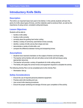
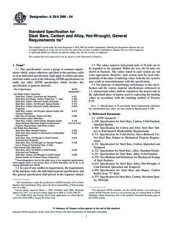
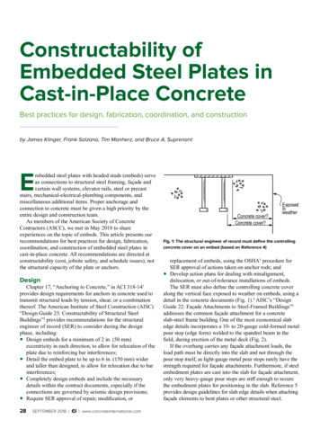
Constructability ofEmbedded Steel Plates inCast-in-Place ConcreteBest practices for design, fabrication, coordination, and constructionby James Klinger, Frank Salzano, Tim Manherz, and Bruce A. SuprenantEmbedded steel plates with headed studs (embeds) serveas connections to structural steel framing, façade andcurtain wall systems, elevator rails, steel or precaststairs, mechanical-electrical-plumbing components, andmiscellaneous additional items. Proper anchorage andconnection to concrete must be given a high priority by theentire design and construction team.As members of the American Society of ConcreteContractors (ASCC), we met in May 2018 to shareexperiences on the topic of embeds. This article presents ourrecommendations for best practices for design, fabrication,coordination, and construction of embedded steel plates incast-in-place concrete. All recommendations are directed atconstructability (cost, jobsite safety, and schedule issues), notthe structural capacity of the plate or anchors.DesignChapter 17, “Anchoring to Concrete,” in ACI 318-141provides design requirements for anchors in concrete used totransmit structural loads by tension, shear, or a combinationthereof. The American Institute of Steel Construction (AISC)“Design Guide 23: Constructability of Structural SteelBuildings”2 provides recommendations for the structuralengineer of record (SER) to consider during the designphase, including:Design embeds for a minimum of 2 in. (50 mm)eccentricity in each direction, to allow for relocation of theplate due to reinforcing bar interferences;Detail the embed plate to be up to 6 in. (150 mm) widerand taller than designed, to allow for relocation due to barinterferences;Completely design embeds and include the necessarydetails within the contract documents, especially if theconnections are governed by seismic design provisions;Require SER approval of repair, modification, or 28SEPTEMBER 2018 Ci www.concreteinternational.comConcrete cover?Concrete cover?ExposedtoweatherFig. 1: The structural engineer of record must define the controllingconcrete cover on an embed (based on Reference 4)replacement of embeds, using the OSHA3 procedure forSER approval of actions taken on anchor rods; andDevelop action plans for dealing with misalignment,dislocation, or out-of-tolerance installations of embeds.The SER must also define the controlling concrete coveralong the vertical face exposed to weather on embeds, using adetail in the concrete documents (Fig. 1).4 AISC’s “DesignGuide 22: Façade Attachments to Steel-Framed Buildings”5addresses the common façade attachment for a concreteslab-steel frame building. One of the most economical slabedge details incorporates a 10- to 20-gauge cold-formed metalpour stop (edge form) welded to the spandrel beam in thefield, during erection of the metal deck (Fig. 2).If the overhang carries any façade attachment loads, theload path must be directly into the slab and not through thepour stop itself, as light-gauge metal pour stops rarely have thestrength required for façade attachments. Furthermore, if steelembedment plates are cast into the slab for façade attachment,only very heavy-gauge pour stops are stiff enough to securethe embedment plates for positioning in the slab. Reference 5provides design guidelines for slab edge details when attachingfaçade elements to bent plates or other structural steel.
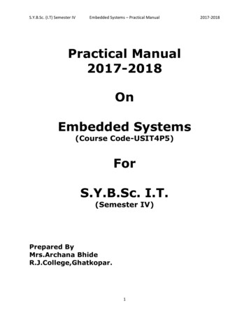
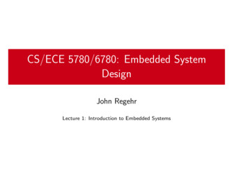
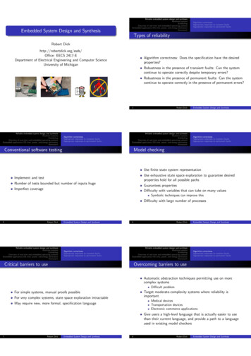
Based on discussions at the recent ASCC meeting, weassembled additional recommendations for the SER:Detail reinforcing bars at any embed with a plate thicknessexceeding the concrete cover minus the clearance requiredper Section 2.3.1 of ACI 1176 (Fig. 3 and 4). The SER willbe in the best position to evaluate the effects such a detailwill have on structural behavior, while also considering theeffects it will have on cost and schedule. Options mightinclude:Increasing the cover for the entire reinforcing bar curtain;Providing offset bends in the affected bars (note that thismay necessitate additional ties);the plate as an opening (terminating affected Treatingbars and adding splice bars to maintain continuity 1 in. @ 12 in.2Clear distance1 Pour stopOverhangNotes: 1/2mi in.n.2 in. min. across the plate dimension); andUsing a thinner plate, with stiffeners oriented parallel tothe outer bars.Adjust stud spacing when plates are used at the edges ofwalls, columns, or slabs. Embed details often indicate thatstuds are about 2 in. from the edge of a plate; however, ifthe plate is to be located at an edge, then the first row ofstuds will probably conflict with a reinforcing bar (Fig. 5).It may also be necessary to consider the effect of a chamferat a wall or column corner;31The pour stop is designed for wet weight of concrete, concrete fluidpressure on the vertical leg, and a 20 lb/ft2 load.2The slab is designed for self weight and all superimposed loads.3The overhang is generally less than 12 in. for light-gauge metal pour stops.BarClear distanceFig. 2: A typical pour stop detail for a slab on metal deck (based onReference 5) (Note: 1 in. 25 mm; 1 lb/ft2 0.96 kN/m2)Fig. 4: An illustration of the requirements in Section 2.3.1 of ACI 117,which specifies that the clearance between embedded items and thenearest reinforcing bar shall be the greater of the bar diameter,largest aggregate size, or 1 in. (25 mm). The figure in the associatedcommentary indicates that the clear distance is a toleranceFig. 3: Reinforcing bars must clear embed plates and studs by theclearance provided in Section 2.3.1 of ACI 117, and the SER mustprovide details showing how the clearance is to be maintained. Thisis particularly critical when the embeds have very thick plates(photo courtesy of Bruce Suprenant)Fig. 5: A reinforced concrete wall with embeds and penetrations,shown prior to closure of the formwork. The embeds adjacent to thewall penetrations interfere with the vertical bars in the wall(photo courtesy of Bruce Suprenant)www.concreteinternational.com Ci SEPTEMBER 201829
special studrail details when the concrete slopes or Providereduces in thickness, such as at a balcony. For instance, an 8 in. (200 mm) thick slab may have a 3/4 in. (19 mm)step-down to accommodate a balcony door, and thebalcony may slope for drainage. The final slab thicknesswill then be about 7 in. (175 mm). If stud rails are used toreinforce the balcony, the stud height must be reduced toaccommodate the depth change as well as maintainadequate cover for the exterior environment;Avoid embeds with attachments welded on both sides ofthe plate, as formwork will need expensive modificationsto accommodate the outer attachment and thus may not bereusable. Such embeds are typically more difficult to setwithin tolerances. The cost-effective option is to weld oranchor attachments to embed plates after concrete hasbeen placed;Design embeds at tops of walls and curbs, slabs, and otherlocations so that they do not interfere with concreteplacement. Consider options such as discontinuousembeds. Also, consider allowing wet-setting embeds inaccordance with ACI provisions for precast and tilt-upconstruction7;Provide direction to the concrete contractor if the perimeterembeds must be positioned to offset slab shortening due topost-tensioning;Indicate whether reinforcing bar clearance next to the plateis important. ACI 117 requires at least 1 in. (25 mm)clearance between embed plates and reinforcing bars, toallow concrete to flow between the bar and plate (Fig. 4);Perform a constructability review that includes checks forinterference between embeds and bars or tendons. Beparticularly careful to avoid locating slab embed platesdirectly above post-tensioning anchors. Also note that thedetails may have to be revisited after bidding, forcoordination with the architect and specialty engineersresponsible for post-tensioning and cladding;Specify nail and air holes in fabricated items to facilitateconstructability (see “Fabrication”);Specify whether the position of the embed, reinforcingbars, or post-tensioning tendons controls when interferenceoccurs;Design fewer standardized embed types;Provide an embed schedule for clarity; andRequire an embed coordination meeting between thedesign and construction teams, separate from the concretepreconstruction meeting (see “Coordination”).FabricationACI Committee E703, Concrete Construction Practices,recommends in “Cast-in-Place Walls (CCS-02[00])” that“weld plates, angles or channels, frames for openings, loadingdock equipment, edge protection and trench drains should bepredrilled for nailing to the forms.”8 Concrete contractors mayinclude the predrilling requirement for embeds in the scope ofwork, which is submitted to the general contractor or30SEPTEMBER 2018 Ci www.concreteinternational.comFig. 6: Embed plates require small diameter holes for installation onwall form (photo courtesy of Ceco Concrete Construction)construction manager (the controlling contractor). Concretecontractors may condition their bids upon the timely deliveryof embeds with plates predrilled for nailing to forms. Often,however, the requirement is neglected, and embeds areshipped to the site without predrilling. This causes delays, asembeds must be shipped back to the fabricator’s shop fordrilling. The SER should address the issue in the projectspecifications by requiring predrilling of the plates. This willreduce confusion and minimize delays.At a minimum, embeds that will be installed on formworkwill need erection holes at all four corners of the embed plate(Fig. 6). Plates exceeding about 24 in. (600 mm) in widthrequire additional holes spaced no more than 18 in. (450 mm)apart to ensure the plate remains in contact with the formworksheathing during concrete placement. Holes should be 3/16 in.(4.75 mm) in diameter, to accommodate a 16d nail or a No. 8(4 mm) drywall screw. Holes this size must be drilled—theyare too small to be punched.One or more larger holes will be necessary for embeds thatwill be set in tops of slabs. In addition to pre-drilled cornerholes, embeds larger than 24 in. in both directions placed onthe top of slabs need an air relief hole or “sight hole” to verifythat the concrete flows under the plate (Fig. 7). The air reliefhole can be 3/4 in. in diameter and can therefore be punched.CoordinationTo maximize embed constructability, the design andconstruction team should make coordination their highestpriority. This is especially critical when there are separatework packages and thus different subcontractors placing thereinforcement, the forms, and the concrete. The SER shouldrequire an embed coordination meeting, as formwork, embed,and reinforcing bar placing drawings need to be carefullyreviewed along with structural steel and cladding erectiondrawings. The SER should send an agenda and minutes torelevant members of the design and construction teams at
least a week before and after themeeting date, respectively.The coordination paragraphs in twosections of the AIA MasterSpec guidespecifications “Section 051200:Structural Steel Framing”9 and “Section055000: Metal Fabrications”10 requirethat embeds and embed drawings befurnished to other trades withoutdelaying the work. The concretecontractor provides a schedule of workthat the controlling contractor uses to setdeadlines for approval of embeddrawings and shipping of embeds. Theconcrete contractor needs to review thedrawings at least 2 weeks beforefabrication starts, and the concretecontractor needs embeds at least2 weeks prior to installation. The firstdeadline allows sufficient time to checkthe drawings for possible placementdifficulties (including conflicts withreinforcing bars). The second deadlineallows sufficient time to verify theaccuracy of materials received andphysically check for placementdifficulties. The controlling contractormust take into account any extra leadtime that may be required to procurenonstandard conditions such asgalvanized or stainless steel embeds.The concrete contractor does nothave control over other subcontractors.Thus, it is imperative that thecontrolling contractor enforces thecoordination requirements set forth inthe project specification, includingpredrilling of plates. This includesproviding the embed layout drawingsearly so that changes, if necessary, canbe made to the reinforcement barplacing drawings. If the embeds are notreceived 2 weeks before placement,delays or repairs may result; and theconcrete contractor will be justified indemanding reimbursement foradditional costs.The concrete contractor should haveone person on site responsible formanaging embeds to ensurecoordination between differentsubcontractors supplying embeds, thatdrawings are received and reviewedpromptly for accuracy, to verify that thedrawings satisfy the architectural and(b)(a)Fig. 7: Air holes are used to ensure that concrete flows under plates (photos courtesy of (a) CecoConcrete Construction; and (b) Conco Companies)structural specifications, and to identifypotential conflicts with reinforcing barsand post-tensioning.This person should track:Invoices and shipping tickets thataccompany embed deliveries;Embed inventories, including types, quantities, delivery dates, and backorders; andProblems, including discrepancies,errors, shipping issues, or conflicts.This person should produce an embedlist for each placement or each floor, andthis person must ensure that the correct NEW and UPDATEDACI SpecificationsSpecifications for Structural ConcreteACI’s 301-16 is a specification that architects andengineers can apply to any construction projectinvolving structural concrete.Member Price: 59.00Regular Price: 99.50Field Reference ManualACI’s new Field Reference Manual is a compilation ofACI 301-16, “Specifications for Structural Concrete,” andadditional ACI documents.Member Price: 159.00Regular Price: 199.50Order at www.concrete.org orcall us at 1.248.848.3800www.concreteinternational.com Ci SEPTEMBER 201831
Fig. 8: Embeds must be stored in a designated area and supportedon cribbing or pallets. In this example, several of the embed platesare curved, warped. or twisted. Slight imperfections can becorrected during installation once embeds are nailed in place. Note,however, that these plates lack nail holes. If adequate correctionscannot be made, deformed embeds should not be used(photo courtesy of Ceco Concrete Construction)embeds are delivered to each placement location at theappropriate time prior to concrete placement. A designatedarea on site will be needed for the storage of all embeds (Fig. 8).Embeds should be clearly marked and stored in separate cratesor on pallets, out of the soil and mud, and protected fromsnow and ice during winter.When curved, warped, or twisted embeds (Fig. 8) arereceived, the fabricator should be notified, using identificationnumbers and photographs. Many imperfections can be correctedas deformed embeds are being nailed in place. If imperfectionscannot be corrected, the deformed embeds must be replaced.By notifying the supplier in advance, delays will be minimized.The concrete contractor must advise the SER if embedscannot be placed due to interferences with reinforcing bars,post-tensioning tendons, or other items. The contractor mustreceive approval from the SER on any modifications prior toconcrete placement. This process, including the timing ofsubmittal and approval, should be discussed at thecoordination meeting. If a modification such as bending ofheaded studs is allowed (Fig. 9), for example, the SER shouldset the maximum bend (a bend angle of 15 degrees would beconsistent with AWS11 testing protocols) and appropriate fieldtest for the modification.Fig. 9: Embeds with studs that have been bent in the field(photo courtesy of Conco Campanies)embed locations and alter formwork as needed prior tosubmitting formwork shop drawings for review. Planning isalso necessary to minimize damage to formwork panelscaused by installation of embeds—particularly on formworkcomprising steel frames or aluminum panels.LayoutTo ensure success, the concrete contractor must considerforming, layout, installation, concrete placement, and postplacement activities. The following sections describe many ofthe associated issues.The field engineer should double check that dimensions aremeasured from top of slab and not “elevations.” Layoutshould be done by trained and experienced personnel. Thelayout crew must:Locate the centerline of embeds and spot check embededges and sizes on initial placements and when exactlocation and placement are critical;Ensure that the layout crew has reviewed the latestapproved shop drawings;Make sure there are sufficient control lines to provideaccurate and consistent layout;Check control lines back to primary control on ground, atleast every other floor;Double check dimensions prior to performing field layout.When using dimension strings for embeds, use the layoutfrom column grid lines, as this is more accurate thanmeasuring each individual dimension; andWhile the concrete contractor usually provides the layoutand sets embeds provided by others, that is not always thecase. Some follow-on trades, such as curtainwall and woodframing subcontractors, may request that they locate andset their own embeds. This should not be an issue if it doesnot delay the concrete placements. Regardless of whoprovides the layout and sets embeds, rework and associatedback charges can be significant and thus need to bediscussed at the coordination meeting.FormingInstallationConstructionEmbed plate sizes or locations may force altering offormwork tie locations. Check formwork drawings against32SEPTEMBER 2018 Ci www.concreteinternational.com The layout crew should begin by marking adjacentreinforcing bars with a white paint stick to fix the general
location and elevation of embeds. The crew can thenloosely attach embeds to the reinforcing bars, using tiewire routed through the previously discussed holes in theembed plates.Many concrete contractors then set the forms and tightenthe form ties near embeds to maintain contact between theforms and embed and minimize paste between embeds andform. It may be necessary to place a bent reinforcing bar ora slab bolster behind embeds to position the plate slightlyoutboard of its final position. When the form is closed andthe form ties are tightened, the reinforcing bar or slab bolsterwill deform, thereby clamping the form snug againstembeds. Other contractors set the form and run tie wire fromembeds through the form. This often requires drillingmultiple holes in the form to locate the tie wires. Once thetie wire is located, it is pulled through the form to snug theform against embeds.At wall and column corners, the chamfer is generallyremoved as required to allow the edge of the embed plate tobe flush with the face of the concrete element.Concrete placementAll embeds should be set prior to concrete placement.Placement watch personnel should keep finishers and otherpersonnel from stepping on embeds or moving them duringplacement and ensure proper consolidation at embeds. Whenplacing concrete around a slab embed, it is important to directconcrete flow in one direction, with the vibrator operator closeby to watch the concrete come out the other side. The “sighthole” in a slab embed assists the vibrator operator in makingsure that concrete is under the plate and there is minimaltrapped air.Post concrete placementAs soon as possible after stripping the forms, the concretecontractor should use scrapers or chisels to clean groutleakage that could affect attachments to embed faces. Theconcrete contractor’s quality assurance crew should surveycritical embed locations to be sure they have been correctlyplaced, document the as-built conditions, and advise the SERimmediately of anything out of tolerance. If issues arediscovered, the quality assurance crew should confirm thecause and provide corrective action for future embedplacements.Special TopicsExpansion jointsThe concrete contractor must ensure that embeds that formexpansion joints:Are not warped or twisted (inspect embeds beforeinstallation);Are set plumb and level (embeds must be securely tied tothe reinforcing bars);Remain in the correct position during concrete placement(workers must avoid walking on embeds); and SealFig. 10: Embeds for expansion joints must be installed toaccommodate joint takeFig. 11: Embeds such as trench drains may be set in concrete beforeplacement of the slabafter forms are stripped (embeds must be aligned Checkedand plumb to ensure proper installation and function ofexpansion joint material [Fig. 10]).Long embeds could comprise shorter embeds that havebeen tack welded together after setting to ensure alignmentbefore, during, and after concrete placement. This solutionmust be discussed and agreed at the embed coordinationmeeting.Slab embedsIn slab-on-ground construction, it may be possible to settrench drains, plates, bollards, and other embeds in concretethe day before slab placement, with the reinforcing bars inplace, to ensure no movement during the main placement(Fig. 11). This approach should also be discussed at the embedcoordination meeting.TolerancesConcrete contractors set embeds to meet tolerances inSection 2.3 of ACI 117.6 The horizontal or vertical centerlinesof the assembly can vary from the specified location by 1 in.The surface of the assembly can vary from the surface of theconcrete by 1/2 in. (13 mm) if the assembly is larger than12 in. (300 mm). For 12 in. or smaller assemblies, thevariance is 1/2 in. per 12 in. but not less than 1/4 in.(40 mm/m but not less than 6 mm).www.concreteinternational.com Ci SEPTEMBER 201833
The trades furnishing embeds to the concrete contractorsmay want or need tighter tolerances. For instance, Section7.5.3. of the AISC Code of Standard Practice12 requires thatembeds to receive structural steel be set to a toleranceconsistent with those specified in Section 7.13 for the erectionof structural steel. The façade or curtain wall, elevator, stairs,operable partitions, and other trades may request differenttolerances. It is the responsibility of the design team tocoordinate these tolerance requirements and indicate whichcontrols. This issue must also be discussed at the embedcoordination meeting. Since this is discussed after bidding andcontract signing, the concrete contactor will submit a bid forembeds consistent with ACI 117 tolerances. Tolerances thatdiffer from ACI 117 may result in a change order.Alternatively, Mohr and Harris13 present options for embeddesign and construction in a design-build environment.References1. ACI Committee 318, “Building Code Requirements for StructuralConcrete (ACI 318-14) and Commentary (ACI 318R-14),” AmericanConcrete Institute, Farmington Hills, MI, 2014, 519 pp.2. Ruby, D.I., “Design Guide 23: Constructability of Structural SteelBuildings,” American Institute of Steel Construction, Chicago, IL, 2008,50 pp.3. “Safety and Health Regulations for Construction, Standards—29CFR 1926 Subpart R—Steel Erection,” Occupational Safety and HealthAdministration, Washington, DC, Aug. 2010.4. Concrete Reinforcing Steel Institute, “RFIs on Formliners, Cover,and Embedments,” CRSI Detailing Corner, Concrete International, V. 33,No. 2, Feb. 2011, pp. 66-70.5. Parker, J.C., “Design Guide 22: Façade Attachments to SteelFramed Buildings,” American Institute of Steel Construction, Chicago, IL,2008, 213 pp.6. ACI Committee 117, “Standard Specification for Tolerances forConcrete Construction and Materials (ACI 117-10) and Commentary(ACI 117R-10) (Reapproved 2015),” American Concrete Institute,Farmington Hills, MI, 2010, 76 pp.7. “Concrete Q&A: Wet Setting Weld Plates in Tilt-Up Panels,”Concrete International, V. 28, No. 6, June 2006, p. 88.8. ACI Committee E703, “Cast-in-Place Walls (CCS-02[00]),”American Concrete Institute, Farmington Hills, MI, Jan. 2000, 102 pp.9. “MasterSpec Section 051200: Structural Steel Framing,” AmericanInstitute of Architects, Washington, DC, 2017.10. “MasterSpec Section 055000: Metal Fabrications,” AmericanInstitute of Architects, Washington, DC, 2017.11. D1 Committee on Structural Welding, “Structural Welding Code –Steel (AWS D1.1/D1.1M),” American Welding Society, Miami, FL,Mar. 2016, pp. 245-259.12. AISC Committee on the Code of Standard Practice, “Code ofStandard Practice (ANSI/AISC 303-16),” American Institute of SteelConstruction, Chicago, IL, June 2016, 70 pp.13. Mohr, B.A., and Harris, S.K., “Marrying Steel to Concrete—ACase Study in Detailing,” STRUCTURE magazine, Nov. 2011, pp. 34-36.Selected for reader interest by the editors.34SEPTEMBER 2018 Ci www.concreteinternational.comACI member James Klinger is aTechnical Representative with theConco Companies, based in the SanFrancisco, CA, Bay Area. Klinger is amember of Joint ACI-ASCC Committee117, Tolerances, and ACI Committee 134,Concrete Constructability. He also serveson the ASCC Technical Committee.Klinger received his master’s degree instructural engineering from the University of Maryland.ACI member Frank Salzano is Directorof Quality Control for Ceco ConcreteConstruction, Centreville, VA. He hasworked in concrete construction formore than 30 years, in his own concreteconstruction business, for self-performgeneral contractors, and for concretecontractors. Salzano is a member of JointACI-ASCC Committee 117, Tolerances. Hereceived his BS in civil engineering andMS in construction management from Virginia Tech, Blacksburg,VA. Salzano is a licensed professional engineer in Virginia andother jurisdictions.Tim Manherz is the Senior VicePresident of Operations at TASCommercial Concrete, Houston, TX.He is President of the Tilt-Up ConcreteAssociation (TCA) Board of Directorsand is a member of the ASCC Board ofDirectors, Membership Committee, andTechnical Committee. He is a member ofACI Committee 330, Concrete ParkingLots and Site Paving, and an associatemember of Joint ACI-ASCC Committee 117, Tolerances, and ACICommittees 302, Construction of Concrete Floors, and 360,Design of Slabs on Ground.Bruce A. Suprenant, FACI, is the ASCCTechnical Director. He is a member ofseveral ACI committees, including theACI Construction Liaison Committee,Technical Activities Committee, and302, Construction of Concrete Floors;and Joint ACI-ASCC Committee 117,Tolerances. His honors include the 2013ACI Certification Award, the 2010 ACIRoger H. Corbetta Concrete ConstructorAward, and the 2010 ACI Construction Award.
pour stop itself, as light-gauge metal pour stops rarely have the strength required for façade attachments. Furthermore, if steel embedment plates are cast into the slab for façade attachment, only very heavy-gauge pour stops are stiff enough to secure the embedment plates for positioning in the slab. Reference 5