Transcription
Table of ContentsRoof Construction Techniques: Pro’s and Con’s . . . . . . . . . . . . . . . . . . . . . . . . . . . . . . . . . . . . . . . . . . . . . 2Trusses: Special Benefits for Architects and Engineers . . . . . . . . . . . . . . . . . . . . . . . . . . . . . . . . . . . . . . . 4Special Benefits for Contractors and Builders . . . . . . . . . . . . . . . . . . . . . . . . . . . . . . . . . . . . . . . . . . . . . . . 5Special Benefits for the Owner . . . . . . . . . . . . . . . . . . . . . . . . . . . . . . . . . . . . . . . . . . . . . . . . . . . . . . . . . . . 5How Does A Truss Work? . . . . . . . . . . . . . . . . . . . . . . . . . . . . . . . . . . . . . . . . . . . . . . . . . . . . . . . . . . . . . . . 6Typical Framing Systems. . . . . . . . . . . . . . . . . . . . . . . . . . . . . . . . . . . . . . . . . . . . . . . . . . . . . . . . . . . . . . . . 8Gable Framing Variations . . . . . . . . . . . . . . . . . . . . . . . . . . . . . . . . . . . . . . . . . . . . . . . . . . . . . . . . . . . . . . 11Hip Set Framing Variations . . . . . . . . . . . . . . . . . . . . . . . . . . . . . . . . . . . . . . . . . . . . . . . . . . . . . . . . . . . . . 13Additional Truss Framing OptionsValley Sets . . . . . . . . . . . . . . . . . . . . . . . . . . . . . . . . . . . . . . . . . . . . . . . . . . . . . . . . . . . . . . . . . . . 15Piggyback Trusses . . . . . . . . . . . . . . . . . . . . . . . . . . . . . . . . . . . . . . . . . . . . . . . . . . . . . . . . . . . . . 17Typical Truss Configurations . . . . . . . . . . . . . . . . . . . . . . . . . . . . . . . . . . . . . . . . . . . . . . . . . . . . . . . . . . . . 18Typical Truss Shapes. . . . . . . . . . . . . . . . . . . . . . . . . . . . . . . . . . . . . . . . . . . . . . . . . . . . . . . . . . . . . . . . . . 20Typical Bearing / Heel ConditionsExterior Bearing Conditions. . . . . . . . . . . . . . . . . . . . . . . . . . . . . . . . . . . . . . . . . . . . . . . . . . . . . . 21Crushing at the Heel . . . . . . . . . . . . . . . . . . . . . . . . . . . . . . . . . . . . . . . . . . . . . . . . . . . . . . . . . . . 22Trusses Sitting on Concrete Walls . . . . . . . . . . . . . . . . . . . . . . . . . . . . . . . . . . . . . . . . . . . . . . . . . 22Top Chord Bearing. . . . . . . . . . . . . . . . . . . . . . . . . . . . . . . . . . . . . . . . . . . . . . . . . . . . . . . . . . . . . 23Mid-Height Bearing . . . . . . . . . . . . . . . . . . . . . . . . . . . . . . . . . . . . . . . . . . . . . . . . . . . . . . . . . . . . 23Leg-Thru to the Bearing. . . . . . . . . . . . . . . . . . . . . . . . . . . . . . . . . . . . . . . . . . . . . . . . . . . . . . . . . 23Tail Bearing Tray. . . . . . . . . . . . . . . . . . . . . . . . . . . . . . . . . . . . . . . . . . . . . . . . . . . . . . . . . . . . . . . 24Interior Bearing Conditions . . . . . . . . . . . . . . . . . . . . . . . . . . . . . . . . . . . . . . . . . . . . . . . . . . . . . . 24Typical Heel Conditions . . . . . . . . . . . . . . . . . . . . . . . . . . . . . . . . . . . . . . . . . . . . . . . . . . . . . . . . . 25Optional End CosmeticsLevel Return . . . . . .Nailer . . . . . . . . . . .Parapet . . . . . . . . . .Mansard . . . . . . . . .Cantilever . . . . . . . .Stub . . . . . . . . . . . .252526262626Bracing Examples . . . . . . . . . . . . . . . . . . . . . . . . . . . . . . . . . . . . . . . . . . . . . . . . . . . . . . . . . . . . . . . . . . . . 27Erection of Trusses . . . . . . . . . . . . . . . . . . . . . . . . . . . . . . . . . . . . . . . . . . . . . . . . . . . . . . . . . . . . . . . . . . . 29Temporary Bracing . . . . . . . . . . . . . . . . . . . . . . . . . . . . . . . . . . . . . . . . . . . . . . . . . . . . . . . . . . . . . . . . . . . 30Checklist for Truss Bracing Design Estimates . . . . . . . . . . . . . . . . . . . . . . . . . . . . . . . . . . . . . . . . . . . . . . 32Floor Systems . . . . . . . . . . . . . . . . . . . . . . . . . . . . . . . . . . . . . . . . . . . . . . . . . . . . . . . . . . . . . . . . . . . . . . . 33Typical Bearing / Heel Conditions for Floor TrussesTop Chord, Bottom Chord, and Mid-Height Bearing. . . . . . . . . . . . . . . . . . . . . . . . . . . . . . . . . . . 34Interior Bearing Conditions . . . . . . . . . . . . . . . . . . . . . . . . . . . . . . . . . . . . . . . . . . . . . . . . . . . . . . 35Ribbon Boards, Strongbacks and Fire Cut Ends . . . . . . . . . . . . . . . . . . . . . . . . . . . . . . . . . . . . . . 36Steel Trusses . . . . . . . . . . . . . . . . . . . . . . . . . . . . . . . . . . . . . . . . . . . . . . . . . . . . . . . . . . . . . . . . . . . . . . . 37Ask Charlie V. . . . . . . . . . . . . . . . . . . . . . . . . . . . . . . . . . . . . . . . . . . . . . . . . . . . . . . . . . . . . . . . . . . . . . . 38Charlie’s Advice on Situations to Watch Out for in the Field. . . . . . . . . . . . . . . . . . . . . . . . . . . . . . . . . . . 41Glossary of Terms . . . . . . . . . . . . . . . . . . . . . . . . . . . . . . . . . . . . . . . . . . . . . . . . . . . . . . . . . . . . . . . . . . . . 42Appendix - References . . . . . . . . . . . . . . . . . . . . . . . . . . . . . . . . . . . . . . . . . . . . . . . . . . . . . . . . . . . . . . . . 481
Builders, Ar chitects and Home Owners today have manychoices about what to use in r oof and floor systemsTraditional Stick Framing – Carpenters take 2x6,2x8, 2x10 and 2x12 sticks of lumber to the jobsite. They hand cut and fit this lumber togetherinto a roof or floor system.Timber Frame – Craftsmen assemble timbers,joinery and braces together to form a selfsupporting skeleton structure.Truss Systems – in two primary forms: Metal Plate Connected Wood Trusses –Engineered trusses are designed anddelivered to the jobsite with a truss placementplan. Trusses are quickly erected and bracedonsite.Engineered Wood Products – I-Joists, Glulam,and LVL (laminated veneer lumber) wood productsare shipped to the jobsite, cut to fit, and made intobeams for the floor system, or into ridge beamsand sloping joists for the roof system. Steel Trusses – Light gauge steel trusses aredesigned and delivered to the jobsite with atruss placement plan. Trusses are lightweight,able to be quickly erected and braced onsite.Each method has advantages and disadvantages. In this book we will look at those pros and cons, and assistyou in identifying which method is best for your situation. We hope to be able to offer you strengths for eachsystem that can help you sell the value-added difference in the product you choose, as well as help you gaina better understanding of the roof systems themselves, with “real world” advice on framing techniques andissues.Stick FramingProsConsLowest cost for materials.if you have the time and theskilled labor required.Slow to install and requiresskilled labor.If trusses cannot be deliveredto the jobsite, conventionalframing may be your onlyalternative.May not be accepted by thebuilding department, as it isnot an engineered product.Requires scarce large lumbersizes (2x8, 2x10)Smaller span capability.High jobsite waste.Timber FrameCreates handsome exposedtimber-frame structures.Slow to install and requiresskilled labor.Difficult to run ductwork,wiring, pipes through.Slow to install and frame in.Hard to insulate2
EngineeredWood ProductsProsConsI-Beams are suitable for steepsloping ceilings.Difficult to run ductwork,wiring, pipes through.Trim-able ends on floors, greatfor angled or rounded walls.Limited use in complicated rooflines, coffered ceilings, etc.Engineered productuniform quality.May require special connections.withGlulam and Laminated VeneerLumber make strong beammaterial.Wood TrussesLowest overall cost.Fast to install.Requires ordinary tools anddoesn’t require skilled labor toinstall.You will want to plan things inadvance. You’ll need a set ofplans for the structure, andyour walls should be close towhere they’re supposed to be.Virtually any roof and ceiling ispossible.Engineered product.Steel TrussesLightweight and stiff,installing is easy and fast.soMore expensive than metalconnector plate wood trusses.May be preferred in lightcommercial/industrialsettings for fire rating.If not analyzed/designed by aleading industry softwareprogram, the joint connectionsmay be suspect.Straight ceilings for ceilingattachment.Virtually any roof and ceilingis possible.Engineered product.3
T r usses: Special Benefits for Ar chitects and Engineers4Trusses bring virtually unlimited architecturalversatility, providing simple solutions to complexdesigns and unusual conditions without inhibitingbuilding design freedom. Using trusses, youhave complete flexibility in interior roomarrangements, too. Using Alpine’s proprietaryVIEW software, truss designers can produceengineered shapes that satisfy virtually anyaesthetic and functional specification by thebuilding design professional.Trusses span longer than conventional framing,so you have more open space to work with inthe interior.Trusses are an engineered and tested product.There are nationally recognized standards for trussdesign and manufacturing of metal plateconnected wood trusses. These standards havebeen adopted by major model building codes.This ensures a quality product. Alpine ProfessionalEngineers are committed to providing the highestquality, cost efficient structural products foryour clients.State of the art truss design software allowsmanufacturers to design them to be: Hurricane-resistant, and/or Withstand heavy snow loads, and/or Support storage areas above the ceiling.Truss manufacturers using Alpine software areavailable for consultation when special framingsituations arise.Wood trusses connected with metal plates enjoyan outstanding record of more than 35 years ofproven performance and durability.You can get a one- or two-hour fire rating withtrusses using the FR-Quik System.
Special Benefits for Contractors and BuildersTrusses go up faster and easier, with less skilledlabor requirements, no matter how complicatedthe roof or ceiling is.Trusses put you under roof faster, which helps indrawing construction loans.The use of preassembled components generatesless waste at the jobsite. This improves safetyand reduces cleanup costs. On-site lossesfrom mis-cutting, theft and damage arevirtually eliminated.Trusses are built in a computer-aidedmanufacturing environment to assure accuracyand quality.Industry standards for manufacturing and handlingassure code-compliance. Building departmentsrecognize these standards and respect thesoftware used to design trusses. While manybuilding departments are wary about inspectingconventional framing, sealed truss designs areeasily inspected.Trusses are lightweight and easy to install,requiring only normal construction tools.The wide nailing surface of 4x2 floor trusses safelyspeeds deck and flooring installation.Expenses are accurately controlled because trusscosts can be predetermined.Open web design allows easy installation ofplumbing, electrical wiring and heating/coolingductwork.Trusses are available locally for fast delivery. Morethan 550 truss manufacturers throughout theUnited States and Canada are backed by theexpertise of Alpine Engineered Products, Inc.Special Benefits for the OwnerThe owner can enjoy peace of mind, knowing thatthe trusses have been professionally engineeredand quality manufactured for the specific job.Floor trusses can conceal mechanical services,leaving a clear plane for ceiling installations. This isideal for finished rooms in a lower level.The resiliency of wood provides a floor system thatis comfortable.Trusses provide clear spans so interior walls canbe moved easily during remodeling or whenmaking additions. It is very economical to remodelhomes with trusses, versus frame houses.Wood is a natural insulator because it is composedof thousands of individual cells, making it a poorconductor of heat and cold.Roof truss details such as tray, vaulted or studioceilings improve the appearance and comfort ofhomes, offices, churches and commercialbuildings.5
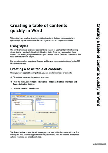
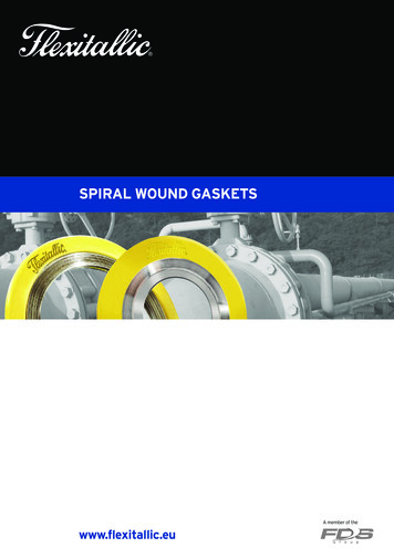
How Does a T r uss Work?A truss is a frame that supports loads by efficientlytransferring its forces to end supports. While stickframing might use larger 2x8, 2x10, etc. members(which are expensive and hard to find withoutgoing into old growth forests), and might requireeither additional beams or interior load bearingwalls, trusses can span a longer distance withoutadditional supports, while using less expensiveand more plentiful 2x4 members, usually arrangedin intersecting triangles.Trusses can span up to approximately 90’,although very long truss spans are morechallenging to deliver, erect, brace and installproperly. While longer trusses may be “wobbly” asthey are lifted off of the ground and onto thebearing walls, once they are properly braced, thetruss system is extremely strong.Mosttrussmanufacturersutilizesophisticated truss design software that iscapable of designing the truss system aswell as the truss itself.The truss designer will workfrom a set of plans, firstcreating a truss placementplan, and then designingeach truss in the system.6
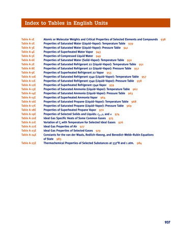
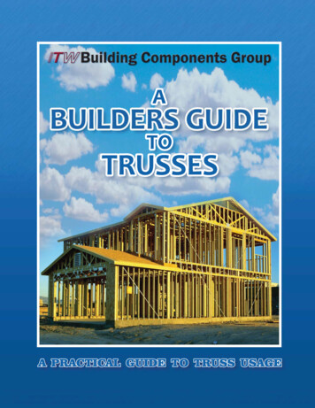
The job is manufactured and delivered to the jobsite, where the contractor / builder erects them andthen quickly braces them.Cutting the lumberManufacturing the trussesDelivering a truckload of trussesErecting the trusses on the jobsiteTemporary bracing systemPermanent bracing system7
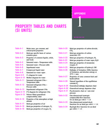
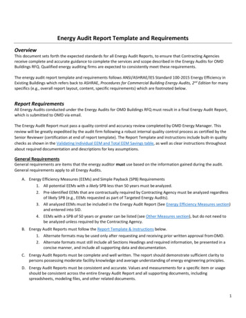
T ypical Framing SystemsTruss framing systems, and the names associatedwith them, vary all over the country andthroughout the world. No matter how they areframed or what they are called, though, trusssystems easily provide tremendous flexibility in thelook of the roof system.The illustrations below are designed to help youvisualize typical framing systems, looking at: A truss placement plan, The overall 3D look of the roof planes in thatroof system, and 3D view of the framing system of trusses.Gable(* See also – Gable framing variations)The most basic (and least expensive) of roofs, agable roof rises vertically on the shorter ends ofthe building, with sloping planes on either side,which meet in the middle. In our example you’ll8find a gable frame on either end, each supportedby the continuous wall underneath it, and commontrusses in between, each of which spans from onewall to the other.This roof system could have a sloping ceiling or tray ceiling, if desired.
Hip set( * See also – Hip set framing variations )Dutch (Boston) Hip setNotice the vertical rise in the middle of the hip set end plane.9
Tudor HipA tudor hip provides some interesting sloping planes at either end,and is generally cheaper to build than a full hip set.Floor system( * See also – Floor Truss Systems )10
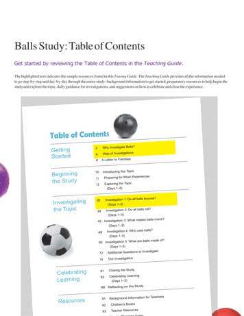
Gable Framing VariationsDropped gableIf the roof eave extends beyond the end wallenough to require support for the roof sheathing,then a dropped gable is specified. The top chordof the gable end is dropped down enough so thatthe builder can run outlookers from the fascia andback to the first common truss. This providesenough additional support for the sheathing.Clear Span GableWhile most gable ends have continuous supportunder their bottom chords, a clear span gablemust span from one wall to another. It has to havediagonal webs to help distribute the load out to thewalls, but it also needs to have vertical gable studsto help the gable sheathing resist lateral windforces.Alternative methods for framing a structural gable include the truss manufacturer providing a full gable truss(with just gable studs) and a full common truss, which would be fastened together with the gable end facingthe wind, or providing studs along the outside face of a common truss.11
Transition gableA transition gable end truss occurs when a run ofsmaller span trusses leads up to parallel longerspan trusses. The first longer span truss will facelateral wind loads in the area where it is notshielded by the smaller span trusses. In the12smaller span area of that same gable, it doesn’thave continuous support under its bottom chord.A transition gable, therefore, has diagonals to helptransfer loads in the smaller span area, and gablestuds in the part that faces the wind.
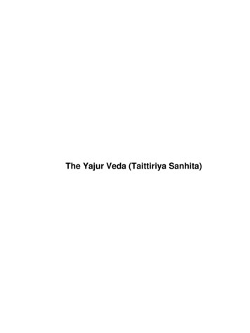
Hip Set Framing VariationsUnder the planes of a hip set roof, there are manydifferent methods used to frame the trusses.Preferences for any given system hinges uponbuilder preferences, manufacturing efficiencies,cost, and ceiling requirements. Some of the mostcommon hip systems are outlined below.StepdownA stepdown hip set provides a girder truss, with ahip jack running from the corners up the ridge untilthey meet the hip girder.The builder must provide support for thehip ridge, usually in the form of blocking, orhip cats, in between each hip truss up tothe peak.MidwestThe Midwest hip set also provides a girder truss,with hip trusses that step up to the peak.However in a Midwest hip set, you run a rafter upfrom the corner of the front wall to the hip girder.Hip cats must be field cut and installedbetween the hip trusses if a dropped-ingable is not provided (for more info seeDropped-In Gable)All the bottom chords of the end jacks run to thehip girder, allowing for better attachment of thedrywall on the ceiling.CaliforniaNotice that a long rafter is provided for the lengthof the hip ridge so no cats or field support of theridge is necessary.All the bottom chords of the end jacks runto the hip girder, allowing for better attachmentof the drywall on the ceiling, and the top chords ofthe end jacks run all the way up to the hip ridge.Proper support of extended top chords is critical.13
NortheastIn a northeast hip set, you will find a short jackstarting at the corner and running up the hip ridge.This hip jack stops at a sub-girder. All end jackbottom chords run to the hip girder, allowing forbetter attachment of the drywall on the ceiling.Hip cats must be field cut and installedbetween the hip trusses. Works well withdual-pitched hip systems.TerminalTerminal hip sets are used in spans up to about 30'to 32'. A ridge rafter runs from the corner up tothe peak of the hip, and a sub-girder, locatedabout half way to the peak, carries the side jackbottom chords while their top chords run up to theridge rafter.Standard TerminalThe standard terminal hip set is used for very smallspans, i.e. up to about 18’ to 20’. The two hipjacks running up the corners and the center endjack all connect at the peak, which can make thepeak connection difficult on longer spans.14
Drop-in Purlin FrameAn alternative method for providing support up theridges of a hip set is for the truss manufacturer todrop the flat top chord of the hip trusses by 1 1 /2 ”,and provide a special purlin frame (in red) for theframing crew to drop in above the hip girder.The frame fits in the plane of the front face of thehip set, and provides additional rigidity to the roofsystem. Nailing sheathing into the 2x4 flat studs isalso convenient.Additional T r uss Framing OptionsValley Set – A valley set is a group of trusses whichsit on top of other trusses in order to change theway the roof looks. In the example below, withoutvalleys, we would have an empty “hole” in the roofbehind the girder. This would need either stickframing, or a valley set.15
Here is what the roof looks like after the valley set (in red) is added.The top chords of the trusses which the valley set sits on must be braced, either by plywood under the valleys,or by alternate bracing.16Images courtesy of Simpson Strong-Tie
Piggyback TrussesWhen roof trusses are too tall to be manufacturedand/or delivered, truss manufacturers will “cap”the trusses and provide piggy back trusses. Thepiggybacks below are shown above the roof sothat the purlin and bracing system can be seen.Special diagonal bracing on the underside of thetop chords (in red) helps brace the purlinsthemselves, and keeps them from shifting out ofplane.Detail of the bracing system, with purlins (blue) and diagonal braces (red).Hip truss shown with piggyback (field applied)17
T ypical T r uss Configurations18
19
T ypical T r uss ShapesThe outside profile of your truss can take on just about any shape you can imagine. Some of the more commontruss shapes appear below.20
T ypical Bearing / Heel ConditionsExterior bearing conditions - The illustrations below show typical support conditions. “Typical” Bottom Chord end conditionTypical conditions include a truss heeland/or with a sloping ceiling, for aring support types for each can be any of the following:Image from Alpine’s VIEW software21
Additional conditions and options include: Crushing at the heel - Sometimes the forcestransferred through the wood into the bearingwall are enough to cause the wood to crush overtime, unless either a bearing block is used, or, ona raised heel condition, the end vertical is runthrough to the bearing wall (so the woodgrain is running up and down, which has a highershear value), or unless the bearing itself is madewider so the forces are transferred through moresurface contact area between the truss heel andthe bearing. Trusses sitting on concrete walls - When the truss sits on a concrete wall, a seat plate may be required asa moisture barrier:22Images courtesy of Simpson Strong-Tie
Other Bottom Chord Bearing conditions:Truss in a hanger:Truss nailed to a girder/ledger (Right end): Top Chord bearing – Trusses can be designed to have support right under the top chord. You will want toshim the bearing solid under the top chord of the truss. Mid-Height bearing – Sometimes the bearingsits between the top and bottom chord of thetruss, and a mid-height bearing block (the 2x6vertical shown here) will be used. Leg-Thru to the bearing – If the bearing isbelow the truss bottom chord, the end vertical ofthe truss can extend down to sit on the bearing.Special bracing may be required.23
Tail bearing tray – If the room calls for a tray orcoffered ceiling very close to the edge of theroom, the truss can look like these tail bearingtray trusses below. The example on the rightcalls for a scab to be attached (an additionalpiece of wood nailed to the face, or both faces,of the top chord at the heel, as shown by thehatched pattern).Interior bearing conditionsInterior bearingTwo trusses sharing a wallBuilt-in kneewall (see 3D image}Special Connection Notes: It is important to properly tie down the truss toyour bearing walls, and not just in areas prone tohurricanes. There are many products that are24designed for this purpose. These productsshould not only anchor the truss into the wall,but also tie the truss down to resist both upliftand lateral forces.Images courtesy of Simpson Strong-Tie
Typical Heel Conditions The top chord that extends beyond the bottomchord and bearing is called an overhang.Plumb CutThe outside cut of your overhang can look like anyof the images below.Square CutSpecial Angle CutDouble CutHorizontal CutOptional End Cosmetics – In addition, the truss overhang can have optional cosmetic framing applied. Level Return: A level return is a horizontalmember creating a soffit under the overhang.The level return on the left side builds up thefascia to 5 1/2 ”, and uses a vertical tostiffen it. The level return on the right sidecreates a box soffit, and is plated to the raisedheel of the truss. Nailer: If some trusses on the job have a 2x6top chord, and some have a 2x4 top chord, youcan keep a consistent fascia edge by applying aripped piece of lumber to the under side of theoverhang. This piece is called a nailer.25
Parapet: On trusses with raised heels, you canbuild in a parapet condition to your truss. Thisparapet can be used to either hide A/C units (ona flat truss, when the A/C unit is located on topof the flat roof), or to hang signage. Additionalbracing may be required for parapet conditions,especially in high wind areas. Mansard ends: For storefront signs or just foranother look, special mansard jack trusses canbe manufactured. Cantilevers and Stubs – Two commonconditions for trusses are cantilevers (when thetruss bottom chord extends beyond the outside26wall) and stubs (when there is a jog in the wall orsome other reason why the truss would be heldback from its original span).
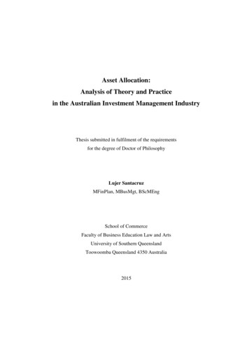
Bracing ExamplesWeb BracingCLB: Continuous lateral bracing (CLB) is 1x4 or2x4 material nailed to the narrow side of a web.The CLB brace here is shown in blue, with diagonalbracing to “brace the brace” shown in red.CLB braces must be fastened across a minimum of3 trusses. If you don’t have a run of at least 3trusses, you must use another type of brace.The truss drawing will show a brace on the web,and will also have a note specifying the brace, asshown to the left here.T-Brace: A T-Brace is 1x or 2xmaterial fastened to the narrow faceof an individual web so as to form a“T” shape.(At right) Truss drawing depicting a T-Brace, and bracing note (below)27
L-Brace - L-Braces are pieces of1x or 2x lumber attached toindividual webs to form an “L”shape. These braces are usuallyspecified for gable ends, whenone face of the truss will besheathed.L-Brace note from a truss drawing (below)Scab Brace – A scab brace isapplied to the wide face of theweb member, using the samesize lumber as the web itself.28Web Block & Other methods for reducing fieldapplied bracing – If you are open to reducing theamount of time your framers are in the roof systemapplying web bracing, and you don’t mind payingjust a little bit extra for the truss package, thesoftware used by truss fabricators allows them touse manufactured solutions like the Web Block(shown, at right), or to increase web grades andsizes to considerably reduce the need for fieldapplied bracing. Talk with your local trussmanufacturer about these alternatives!
Er ection of T r ussesTrusses may be installed manually, by crane, or byforklift, depending on truss size, wall height andjob conditions. Individual trusses should always becarried vertically to avoid lateral strain anddamage to joints and members.Trusses installed manually are slid into positionover the sidewall and rotated into place usingpoles. The longer the span, the more workersneeded to avoid excessive lateral strain on thetrusses. Trusses should be supported at joints andthe peak while being raised.Large trusses should be installed by a crane orforklift employing chokers, slings, spreader barsand strongbacks to prevent lateral bending.Trusses may be lifted singly, in banded groups, orpreassembled in groups.Tag lines should always be used to controlmovement of trusses during lifting and placement.Refer to Handling, Installing and Bracing MetalPlate Connected Wood Trusses (BCSI 1-02) by theTruss Plate Institute, or Wood Truss Erection posterby the Wood Truss Council of America for propermethods of installation.Installation procedures areresponsibility of the installer.conditions and proceduresconsiderably. These areguidelines and maybe proper underconditions.theJobvaryonlynotall29
T emporary Bracing30All trusses must be securely braced, both duringerection and after permanent installation.Individual trusses are designed only as structuralcomponents. Responsibility for proper bracingalways lies with the building designer andcontractor for they are familiar with local and jobsite conditions and overall building design. Alltrusses should be installed straight, plumb andaligned at the specified spacing. Trusses shouldalso be inspected for structural damage.There are two types of bracing. Temporary bracingis used during erection to hold the trusses untilpermanent bracing, sheathing and ceilings are inplace. Permanent bracing makes the trusscomponent an integral part of the roof andbuilding structure. Temporary and permanentbracing includes diagonal bracing, cross bracingand lateral bracing.Permanent lateral bracing, as may be required bytruss design to reduce the buckling length ofindividual truss members, is part of the trussdesign and is the only bracing specified on thedesign drawing. This bracing must be sufficientlyanchored or restrained by diagonal bracing toprevent its movement. Most truss designs assumecontinuous top and bottom chord lateral supportfrom sheathing and ceilings. Extra lateral anddiagonal bracing is required if this is not the case.It is important to temporarily brace the first truss atthe end of the building. One method calls for thetop chord to be braced by ground braces that aresecured by stakes driven in the ground, preferablyoutside and inside. The bottom chord is to besecurely anchored to the end wall. Adjacenttrusses are now set connecting each tocontinuous lateral bracing on the top chord. Theseare typically spaced at 6’, 8’ or 10 feet on centersalong the length of the truss. Refer to BCSI 1-02for diagonal spacing. This top chord bracing willbe removed as the sheathing is applied after theother bracing is completed.Bracing members should be 2x4 nailed with two 16dnails at each cross member unless specified otherwiseon the design drawing. Lateral braces should be atleast 10 feet long. Cross and diagonal braces shouldrun on an approximate 45 degree angle.
Temporary bracing should be 2x4 dimensionlumber or larger and should be 8 feet minimum inlength. Continuous lateral bracing maintainsspacing, but without cross bracing, permits trussesto move laterally. See BCSI 1-02.To prevent dominoing, diagonal bracing should beinstalled in the plane of the webs as the trusses areinstalled. See BCSI 1-02.Full bundles of sheathing should not be placed onthe trusses. They should be limited to 8 sheets toa pair of trusses. Likewise, othe
May be preferred in light commercial / industrial settings for fire rating. Straight ceilings for ceiling attachment. Virtually any roof and ceiling is possible. Engineered product. More expensive than metal connector plate wood trusses. If not analyzed/designed by a leading industry software program, the joint connections may be suspect.