Transcription
Ham Radio 101Home Brewing a 2 Tube 40/80M QRP TransmitterBy Hal Silverman WB6WXODave Ishmael WA6VVLSOARA Education DirectorDirectors Note: This article space has been turned over to anotherSOARA member, Dave Ishmael WA6VVL. Dave’s interest in ham radiocenters on restoring antique radios. He recently built the Lew McCoy twotube QRP Transmitter for 40 and 80M. The article here this month willbe published shortly in Electric Radio and details his home brewproject.The Lew McCoy Memorial 80/40MNovice TransmitterBy David W. Ishmael - WA6VVL2222 Sycamore AvenueTustin CA 92780(714) 573-0901daveishmael@cox.netLike many, my introduction to "radio" was through the pages of Alfred Morgan'sThe Boys' First Book of Radio and Electronics that I found in the HoraceEnsign Junior High School library in Newport Beach, CA, when I was in 6th gradein 1956. My progression in my new hobby was painfully slow. By 7th grade I haddiscovered amateur radio, was given a copy of the 1957 Allied Radio CatalogNo.160 (the cover with the satellite on it), and started to learn the code.Sometime later, a neighbor loaned me his 1957 ARRL The Radio Amateur'sHandbook and I discovered A One-Tube Two-Band Transmitter for the Novice. Icopied that entire construction article by hand before returning his book. I carriedthat dog-eared copy with me for two years as I dreamed about building that xmtr.By 9th grade, my family had moved to SantaBarbara, CA, where the high school had anelectronics program, and even better,"hams". I was not yet licensed, but my plansin building that xmtr went into high-gear.There was a wholesale electronics store inSanta Barbara, but they wouldn't sell mePage -1-
electronic parts without a ham license!! I eventually wound up at a TV-Repairshop a few blocks from where I was living, at the corner of Bath and W.Montecito Streets, and met Jim Clearwater, W6WQJ (SK), a radio-TV techworking in the store.Jim ordered the Shurite Model 950 meter and the 12" x 7" x 3" aluminum chassisfor me, and I must have pestered him almost daily on my way home from schooluntil they arrived. I then spent many an evening in Jim's shack as he showed mehow to cut the holes in the aluminum chassis for the 5Y3GT, 6AG7, and frontpanel octal sockets, pwr xfmr, and Shurite meter. Many of the parts for that xmtrcame out of his junk box including the pwr xfmr. I remember that one of myconcerns was that the pwr xfmr had more current than the one specified!! Boydid I have a lot to learn!!!!My family eventually moved to Albuquerque, New Mexico, and that xmtr wentwith me. I remember that the xmtr was (say) 90% complete, but my memories ofthat xmtr end in New Mexico with it sitting on a top shelf in the entry-way closet.I never put that one-tube 6AG7 xmtr on the air, but the time that Jim spent withme during late '58 and early '59 was just an incredible learning experience.Although this was just the beginning of my radio and electronics education, Ihave never forgotten my first Elmer, Jim Clearwater, W6WQJ, and the 1-tube6AG7 xmtr that he helped me build.Fast-forward to Feb.'93 when I built a "modern" version of that A One-Tube TwoBand Transmitter for the Novice. That attempt was covered in the Dec.'93Electric Radio, Issue#56, Building a Two-Tube 6AG7 80/40M CW Transmitter,pgs. 24-27. During my research for that article, I discovered that Lew McCoy,W1ICP, had originally written that construction article and that it had appeared inthe Nov.'53 QST. Later that year, I had the good fortune of meeting Lew McCoyat the Fort Tuthill Hamfest outside Flagstaff, AZ, where I had an opportunity tothank him for that article in particular, and all the rest that he had written thatserved as inspiration for so many of my projects. In '95 at Tuthill, the last year Isaw Lew, he signed my copy of Lew McCoy on Antennas, and I had my phototaken w/him at Barry's/N6CSW/0's Electric Radio "booth". Lew McCoy, W1ICP,passed away 7/31/2000 after a short illness. He was 84.So, here I am in 2008, 50 years after copying A One-Tube Two-Band Transmitterfor the Novice by hand, that I am once again going to build Lew McCoy's Novice1-tube 6AG7 xmtr. My goal was to build as near a copy of his original as I could,using as many of the original components as I could find. I scanned the photoof Lew's xmtr from the 1957 ARRL The Radio Amateur's Handbook and blew itup to 8-1/2" x 11". I then scaled the front panel dimensions to obtain a drilltemplate for mine. The front panel layout of mine is near-identical to Lew'soriginal. The location of the 6AG7 socket was determined the same way.Page -2-
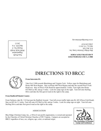
The following are some brief comments regarding the component selection andconstruction of the xmtr: Like Lew's original, mine is built on a Bud P/N AC-408 12" x 7" x 3"aluminum chassis and includes a bottom plate P/N BPA-1595.The finished chassis. All holes were located using a drill template. The chassis was finishedusing 3Msynthetic steel wool using a circular motion. I located the specified Thordarson P/N TS-24R02 pwr xfmr via eBay. Itturns out that the specified TS-24R02 pwr xfmr is a horizontal mountconfiguration while the pwr xfmr on Lew's original is clearly an uprightmount. The correct P/N should have been TS-24R02-U. Modifying theTS-24R02 for upright-mounting by adding angle brackets just didn't lookthe same with the different xfmr end-bells, so, in the end, I abandoned theNOS TS-24R02 for a NOS TS-24R05-U I located via eBay. Both P/N’shave 700-VCT windings. Incidentally, for the record, dimensions from thescanned photo indicate that Lew didn't use the specified TS-24R02-U inhis original either – the one he used is much larger – and his had a largerfootprint than the TS-24R05-U that I ended up using?Even though the TS-24R05-U was NOS, its core was slightly rust-colored.I wire-brushed the core followed by a coat of Krylon glossy black.Before laying out the drill template for the power supply components, Ibench-tested the TS-24R05-U pwr xfmr with the 5Y3GT and 6AG7 todetermine what the max voltage the input filter capacitor would see. Atkey-up, the only load on the B is the 100-k 2-watt bleeder resistor. At115-VAC, the key-up voltage was 484-VDC, a bit too high for a 500-VDCfilter capacitor at higher line voltages. I ended up using two 47 ufd 350VDC filter caps in series with 100-k 2-watt equalizing resistors acrossthem on both sides of the filter choke. The four capacitors were tested forleakage at full-voltage before assembly. The temperature-rise of thexfmr’s core during key-up is minimal as the core stays cold to the touch.The Hammond 9 Hy 40mA filter choke was purchased at AntiqueElectronic Supply (AES, P/N P-T156G) along with the balance of thecomponents.Page -3-
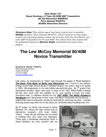
Although Lew's original used a 0-50 or 0-100 mA DC Shurite Model 950meter, I located a Shurite Model 950 0-3 mA DC meter via eBay. Itrequires a 27 ohm current shunt for a 0-60 mA full-scale indication.I will typically mount the 365uuf variables (AES P/N C-V365) using thetapped 6-32 holes on the front-face of the variable (if they aren't tapped, Itap them). However, Lew used standoffs on the bottom of the variablesand mounted them from two holes on the top of the chassis. I followedsuit and used four 9/16" 6-32 hex standoffs (2 per cap) to position thecapacitor’s shafts at the center-line of the front panel.I didn't use ceramic feed-throughs for mounting the 42-turn B&W 3016 coilbut chose 3/8” ceramic standoffs (HH Smith P/N 2642) with the wiringgoing through ¼" rubber grommets in the chassis.Experience fromprevious projects using Lew's basic design has shown that 70-turns ofB&W 3016 was just too much inductance and I reduced it to the 42-turnsused in this project. I soldered a short stub of 0.036" dia. wire to the coil'scenter-tap and output side and terminated the connecting jumper with thepin removed from a 7-pin miniature tube socket. Even though this comboprovides just enough contact pressure for a good connection, you stillneed to be careful of connecting the center tap because of the coil'srelatively small 24 AWG wire (I would have preferred a switch).Since I didn't follow Lew's wiring, the location of most of the 6-32 hardwareon the top of the chassis is different, and, as a nod to the original, I usedround-head 6-32 hardware in the assembly.External-tooth lock washers were used throughout the assembly.Page -4-
“Hidden” on the rear panel and much different than Lew’s xmtr (but"transparent" from the front panel) is an IEC AC-inlet connector so that Icould use a detachable 3-conductor power cord, a 3AG fuse holder (RadioShack P/N 270-364), and an SO-239 ant connector.A NOS GE 5Y3GT and NOS HP 6AG7 came from my tube supply. The6AG7 was given to me by Barry Wiseman/N6CSW/0 when I visited ER inDurango, CO, in Jul.'93 (see ER#53 Sep.'93).Other than the time locating and purchasing the components,dimensioning Lew’s original xmtr, preparing the wiring diagram and drilltemplates, and drilling the chassis, took the most time. Fortunately, I haveall the Greenlee chassis punches I needed: ½”, 5/8”, ¾”, 1”, and 2-1/4”.Most of the discrete components were pre-mounted on four terminalstrips, so the actual construction of the xmtr was only 5-1/2 hrs start-tofinish. I used AES P/N P-0501H (pkg of 5) and Radio Shack P/N 274-688(pkg of 4) 5-lug terminal strips cut down as required to mount the variouscomponents.The completed 80/40M xmtr has a maximum measured output power of 6.0 wattsusing a 3746 KHz FT-243 xtal into a 50-ohm dummy load. The output powerwas measured using a Daiwa Model CN-801 SWR & Power Meter. The outputpower ranged from 3.2- to 6.0-watts on 80M depending on the 6AG7 used andthe FT-243's activity. At 115-VAC line, the key-up voltage to the 6AG7 is 480VDC falling to 417-VDC when keyed with an indicated plate current of 32 mA.40M output powers averaged 15% less than 80M and 40M xtals tend to be a bitmore "chirpy". In my "modern" version, I used a 25uuf variable for the specified22uuf cap and adjusted it for minimal "chirp" with a handful of 40M FT-243 xtals.When "properly tuned", the keyed waveform is clean and it sounds OK in themonitor receiver. The output loading capacitor is pretty much ineffective whenusing a 50-ohm load – not surprising since Lew designed his xmtr for a 30-footindoor antenna for both 80/40M. All-in-all, no surprises after building so manyversions of Lew's original design. Performance- and design-wise, Lew's xmtrreminds me of an Ameco AC-1 "on steroids" although the 6AG7 is betterbehaved than the AC-1's 6V6GT and the AC-1 lacks a plate meter.Page -5-
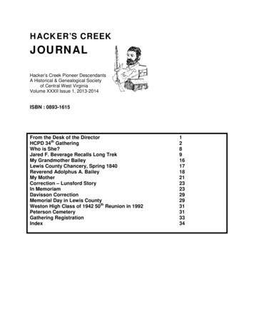
Compare this photo to the original above that appeared in the Nov.'53 QST pg. 28Lew, in his Nov.'53 QST article estimated 14 to build his xmtr. Pricing his xmtrout in a 1954 Allied Radio Catalog No.135 put that price closer to 22 includingparcel post shipping. My cost, using eBay, Mouser Electronics, AES, MarvacElectronics in Costa Mesa, Radio Shack, Action Electronics in Santa Ana, andmy junkbox, approached 235 of which 60 was shipping and handlingcharges!!! The original Millen knobs were supplied by Gary Giles, KF9CM(www.kf9cm.com). A significant portion of the cost was driven by my desire touse as many original parts as I could lay my hands on. Again, my goal was tobuild as near a copy of his original as I could using as many of the originalcomponents as I could find. In a side-by-side comparison of Lew's and myxmtrs, I think I came pretty close!!!!Page -6-
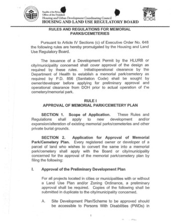
Bottom-view showing most of the major componentsA version of this article will appear in a future issue of Electric Radio (ER)magazine. ER is published monthly by Ray Osterwald, N0DMS, in Bailey, CO.Subscription information can be found at: http://www.ermag.com/Send me an email and I will send you a copy of the original article from QST,parts list, or higher-resolution photos of the construction. I will also be happy toanswer questions via email at daveishmael@cox.net73,Dave – WA6VVLPage -7-
Latest Revision 2/20/2008Page -8-
Page -9-
previous projects using Lew's basic design has shown that 70-turns of B&W 3016 was just too much inductance and I reduced it to the 42-turns used in this project. I soldered a short stub of 0.036" dia. wire to the coil's center-tap and output side and terminated the connecting jumper with the pin removed from a 7-pin miniature tube socket.