Transcription
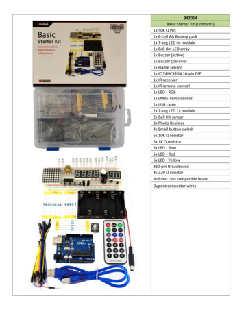
342014Basic Starter Kit (Contents)1x 50K Ω Pot1x 6-cell AA Battery pack1x 7-seg LED 4x module1x 8x8 dot LED array1x Buzzer (active)1x Buzzer (passive)1x Flame sensor1x IC 74HC595N 16-pin DIP1x IR receiver1x IR remote control1x LED - RGB1x LM35 Temp Sensor1x USB cable2x 7-seg LED 1x module2x Ball tilt sensor3x Photo Resistor4x Small button switch5x 10K Ω resistor5x 1K Ω resistor5x LED - Blue5x LED - Red5x LED - Yellow830-pin Breadboard8x 220 Ω resistorArduino Uno compatible boardDupont connector wires
Inland Uno R3:UUUNO R3 Summary:MicrocontrollerOperating VoltageInput Voltage (recommended)Input Voltage (limits)Digital I/O PinsAnalog Input PinsDC Current per I/O PinDC Current for 3.3V PinFlash MemorySRAMEEPROMClock SpeedLengthWidthWeightATmega3285V7-12V6-20V14 (of which 6 provide PWM output)640 mA50 mA32 KB (ATmega328) of which 0.5 KBused by bootloader2 KB (ATmega328)1 KB (ATmega328)16 MHz68.6 mm53.4 mm25 gSee http://arduino.cc for detailed specifications, overviews, schematics, etc. Core functions, code examples, and links tomany of the device libraries can be found in the learning section; refer to the manufacturer's site if using other add-onshields or sensors.The latest Arduino Integrated Development Environment(IDE) necessary for programming your UNO R3 board canbe obtained at http://arduino.cc/en/Main/Software (theDownload menu choice on Arduino.cc)Examples for many basic components can be foundunder the Examples menu. As you install libraries foradditional shields, new examples may be available.Follow the getting started guide found on the arduino.ccweb site. Click Learning, and select Getting started. Clickon the link for Windows, Mac OS X, or Linux for morespecific directions.Getting Started:1. Download the Arduino Environment (IDE) andinstall or unzip/extract the application directory.2. Connect the UNO board to one of yourcomputer's USB port.3. Install the drivers (If the computer does notautomatically download and install thenecessary USB drivers, point the hardware setupto the "drivers" directory of the Arduino IDEapplication.)4. Launch the Arduino IDE application5. Open a sketch example such as "Blink"6. Select your Board from the Tools menu.7. Select the Serial Port used by the board8. Upload the sketch to the boardSketch (code) Examples are included as part of the IDE. If you install device libraries for other components or shields,additional examples may be included and will show up in the list under the IDE File menu.(See: http://arduino.cc/en/Tutorial/HomePage for an overview of the core functions and libraries.)
Components:LEDsLED - Light Emitting Diodes1) Connect a current-limiting resistor (220 ohm)between the LED's positive pin and the 5vpin. Connect the LED's negative pin directlyto your Arduino output pin. -OR2) Connect a current-limiting resistor (220 ohm)between the Arduino output pin and theLED's positive pin. Connect the LED'snegative pin directly to a Ground (GND) pin.Note: LEDs may have "water clear" or color tintedlens.LED - 8x8 Matrix (1588BS or similar)Connect Columns to Arduino Data pins that can bepulled to ground, connect columns using currentlimiting resistors to pins that will output positivevoltage to illuminate the selected LED. gLED - RGB ModuleCurrent-limiting resistors (151 1 5 *10 150 ohm)are already attached to the positive Red, Green, andBlue pins of the LED. Connect the negative (-) pin toyour ground, and the R, G, and B pins to your Arduinooutput pins.If using PWM (Pulse Width Modulation) capableoutputs, you can effectively mix the RGB primarycolors to produce thousands or different outputcolors in the single LED. See:File, Examples, 01.Basic, Fade sketch example inthe it) 7-segment LED (TOS5121AS or similar)Pin 1 is bottom left. Pins 3 and 8 are a commonground. Connect other pins to your Arduino with acurrent limiting resistor.
(4-bit) 7-segment LED (SH5461AS or similar)Pins 12, 9, 8, 6 are grounds for each segment; LEDsegments share pins 11(a), 7(b), 4(c), 2(d), 1(e), 10(f),5(g), 3(h). Transistors are recommended to handlecurrent that could exceed the maximum output ofthe Arduino pins. d-display-arduino-demoSwitchesSmall button switch - momentary contact, NOFor the switch connection, you can use either pairlocated on one side. The connection is NormallyOpen (off) until the button is pushed.Sensors and modulesBall Tilt SensorThis is a very simple switch with a ball inside of thetube. When the sensor is tipped upward past thehorizontal, the ball will short the contacts, closing theswitch. With the top (away from the pins) is tilteddown relative to the horizontal, the switch opens.Flame Sensor (YG1006 or similar)The Flame sensor is a high-speed and highly sensitiveNPN Silicon photo transistor based on the YG1006. Itcan be used to detect fire or other wavelength at760nm 1100nm light. Response time is 15us, supplyvoltage is 3.3-5V; output is analog.IR Receiver (VS1838B or similar)Connect the Vcc pin to your 5V pin and the Gnd to aGround pin. The Signal pin connects to an Arduinoinput pin and will change when the sensor detects anInfrared signal.An IR remote control will send coded pulses based onwhich button you press, or an IR LED will produce acontinuous illumination.The surface-mount LED connects to the signal pin ofthe receiver. It will illuminate when the sensordetects an active infrared source.
Passive & Active buzzersUse as a speaker, buzzer or other audible indicator.The Active buzzer has a protective tag over theopening, note the identifies the positive pin of thedevice, as the rear is covered with epoxy. The activebuzzer will generate a tone as soon as power issupplied to the device.Play a tone or melody using the passive lay-a-melody/The passive buzzer does not have epoxy on the rearPCB, and the positive and negative connections arevisible on the etched board. Passive buzzers musthave a modulated signal supplied to the device (like aspeaker) and would only generate a "click" if DCvoltage is 35 Temperature SensorThe LM35 series are precision integrated-circuittemperature sensors, whose output voltage islinearly proportional to the Celsius (Centigrade)temperature.Basic Temperature Sensor ( 2 to 150 C): Vs 5V in, Ground, Vout 0mV 10.0mV/ CFor code examples, see:LM35 data sheet: http://www.ece.usu.edu/ece o KY001 Temperature sensor moduleResistors1/4 Watt Resistors8pcs 220 ohm5pcs 1K ohm5pcs 10K ohmResistors may come with 4 or 5 identifying colorbands. (When in doubt, use a multimeter to verifythe value.)
Photo ResistorResistance across the pins will be 1 meg ohm orhigher in darkness, dropping to 60 ohms or less inbright light.50K PotentiometerResistance between outer pins is 50K ohms.Resistance between one outer pin and the center(wiper) pin is 0-50K ohms based on position.otherTri-state 8-bit shift register IC SN74HC595N (orsimilar)The datasheet refers to the 74HC595 as an "8-bitserial-in, serial or parallel-out shift register withoutput latches; 3-state." In other words, you can useit to control 8 outputs at a time while only taking upa few pins on your ShiftOutIR Transmitter (Remote Control)Multiple tutorials are available for different remotes,use serial monitoring to identify inputs from yourremote control and use those values in yourprograms. For a typical setup, ntrol830-pin BreadboardPower rails run the length of each side and are colorcoded blue for negative and red for positive. Insiderows of 5 pins each are connected together, but notto each other, and not to the power rails.
Additional Resources:Several sites have hook-up and information and code examples on a variety of sensors, similar to, and including the onesfound in this kit. Some sensors may be loose components or integrated into different board designs. If the documentedsensor uses the same electronic component, then any code sketch documented may work with the sensors found inyour kit. However, depending on the circuit design, the adjustments or sensitivity range may need to be modified slightlyto achieve the desired result. Sites documenting these and other sensors include:Arduino Playground Examples and additional libraries (code sketches available from the IDE File, Examples duino Playground Tutorials: um.HobbyComponents.com: http://forum.hobbycomponents.com/viewtopic.php?f 73&t 1320LinkSprite Wiki - Advanced Sensors Kit for Arduino: http://linksprite.com/wiki/index.php5?title Advanced Sensors Kit for ArduinoTkkrLab.nl (Tukkerlab)Wiki: https://tkkrlab.nl/wiki/Arduino 37 sensorsUniversity of Rhode Island (PDF coursework): 20Learning.pdfFreeduino.org: http://www.freeduino.org/Arduino for Projects (PDF with 1193 projects): y Ada - Introduction to Arduino- step-by-step lessons: nixstuf Arduino Tutorials: http://tronixstuff.com/tutorials/Earthshine Electronics Beginners Guide to Arduino:https://docs.google.com/file/d/0Bw ruMOtRDDgNXI3OTFGZXhIZ2c/edit?usp sharingSheepdog's Guide to Arduino Programming: sted ProjectsArduino Tutorials and ExamplesOsepp Starter Kit TutorialsLED GameVoltage MeterTone Generation7-Segment LED Countdown DisplayArduino MelodyAnalog Read Voltage (example)4-Channel Volt MeterMeasuring Voltage (serial display via IDE)Arduino Digital s.com/9351/arduino-digital-voltmeter/
342014 Basic Starter Kit (Contents) 1x 50K Ω Pot 1x 6-cell AA Battery pack 1x 7-seg LED 4x module 1x 8x8 dot LED array 1x Buzzer (active) 1x Buzzer (passive)