Transcription
ASSEMBLY MANUALMATERIA 101Revision 0424 NOVEMBER 2014
00INDEX0301 - Introduction4208 - Board wiring05060707070802 - KIT ContentsParts listBox ABox BBox CNotes4609 - Calibration4910 - Shell and finishing0903 - Base assembly1404 - Assembling the printing bed1705 - Assembling the carriage2306 - Assembling X carriageand the extruder3007 - Assembling the frame 2011-2015Arduino LLC. All rights reserved.The Arduino name and logo are trademarks of Arduino, registered in the USand in the rest of the world. Other product and company names mentioned hereinare trademarks of their respective companies.Materia 101 is designed by Sharebot for Arduino.
01INTROduction
4Assembly ManualArduino Materia 101We are excited that you have decided to take part in this newindustrial revolution. Like all new technology, it is pioneers likeyou who will lead the real innovation. Your new Arduino 3Dprinter will give you the freedom to create all the objects youcan imagine.This machine is the latest result of the experience we havecollected through all the previous models. Your advice will helpus to improve our products and together with you, we can setnew standards for future desktop printers.We believe that sharing is the best way to innovate so we inviteyou to tell us your thoughts at www.arduino.ccWe look forward to seeing what you will create with theMateria 101!Please note: any parts that you have left over at the end of theassembly, keep them: they should be used as spare parts in the future.INTRODuction
Assembly ManualArduino Materia 10102kit contents5
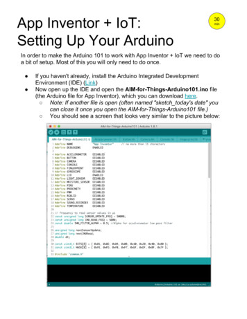
6Assembly ManualArduino Materia 101BASE DIAGRAM:A- Main frameB- Bottom trayC- Z CarriageD- Printing bedF- X CarriageM-Y Left ShoulderN- Y Right ShoulderP- Y Z Bearing guidesQ- X Bearing guidesFig. 1PLEXI CASE DIAGRAM:P1- Spool HolderP2- Spool HolderP3- Spool HolderP4- Spool HolderFig. 1Fig. 2A- Front of caseB- Top of caseC- Right of caseD- Left of caseE- Back of caseF- Left bottom of caseG- Right bottom of caseH- Control KnobFig. 3Fig. 2Fig. 3kit contents
7Assembly ManualArduino Materia 101KIT CONTENTS:BOX A- D8 guide- Hairspray- Z axis stepper motor brass nut block- Plexi kit- Arduino Materia101 stickersA1- Ramps shield- Stepper drivers (5)- LabelsA2- LCD- LCD cableBOX B- SD card- D6 guide- F; M; N; D and Cmetal components- M10 cap nuts (2)- Stepper motors (2)with X/Y pulley- Extruder stepper motor- 1.5 Allen key- 2.5 Allen keyBOX C- Arduino Mega 2560- 220V power cable- USB cable- Glass printing surfaceC1- 12V 5.2A power supplyC2- Z bearingC3- Z bearingC4- End-stops (3)C5- Heat sink greaseC6- LM8UU bearings (8)- Seeger rings (12)C7- Pre-assembled hot-end- Thermistor 100KC8- Grey cable (extrudercarriage wiring)- Grey cable (X axiscarriage wiring)C9- Pulleys (5)- M3 grub screws (5)- 620mm belt- 500mm belts (2)- 160mm beltC10- 40x40 fans (3)C11- 8n nylon bearing carrier- Adhesive feet (4)- O-rings (2)- 5mm 3x6 teflonstand-offs (2)- 3x6mm teflon tube- M3 lock nut- M3x25 boltC12- Display knob- ON/Off switch- Switch sleeve- SocketC13- 3 wire end-stop cables (2)C14- M4 Z axis adjustment screw- M3x25 bolts (4)- M3x40 bolts (2)- M3x35 bolts (4)C15- PVC extruder block- PVC extruder idler- M4x15 bolt- M3x15 bolts (4)- D5 springs (4)- 624ZZ bearing- Steel cable support plateC16- 2.5x100 nylon cable tie- D10 springs (4)- M4x8 bolts (8)- M3x25 bolts (4)C17- M3x6 boltkit contents
8Assembly ManualArduino Materia 101C18- M3x10 bolt- Kapton tapeC24C19- Spiral cable wrap- M3x20 nylon stand-offs (6) - Large shrink tube- Medium shrinkC20- M3 nuts (12)C25- Washers (4)- White LED strip- LED bipolar cableC21- Red connectors (2)- M3x10 nylon stand-offs (8)C22- X/Y metal rod guides (8)- Z metal rod guides (16)- D6 bearings (4)C23- Clips (2)- M3x10 nylon stand-offs (2)- Small shrink tube- 4 wire cables (2)(Z and Y motors)- Pulley- Brass gear wheel- M3 grub screw- Bipolar cable forpower switch- M3x6 bolts (10)TO COMPLETE THEASSEMBLY YOU WILLNEED THE FOLLOWINGTOOLS:- 2.5 Allen Key- 1.5 Allen Key- 3 Allen Key- Medium size cross head(Phillips) screwdriver- Small size flatheadscrewdriver- Seeger pliers- Scissors- Soft solderer- Multimeter- Soldering Tin- Adhesive tape- Hair dryer or lighterNOTESScrews could loosen because of damage or from vibrationso use threadlock on each screw that touches a metal part.Threadlock is a liquid that fills in the gaps between the threadsof screws and hardens into a rubber like substance or glue.We suggest Loctite 221, a low resistance threadlocker for thesome screws. You can also use teflon tape.We suggest using sewing machine oil to lubricate the Z axisbearings and guide rods.Arduino’s Materia 101 Assembly Kit is meant for a user whoalready has experience with assembly. The manual assumesthe user knows how to use a soldering iron.kit contents
Assembly ManualArduino Materia 10103Base Assembly9
10Assembly ManualArduino Materia 101Base AssemblyFig. 1Fig. 2To complete this part you will need:Take the bottom tray and turn it overso the flat side is facing upwards.— Bottom tray— Rubber feet (4)Fig. 3— Z axis motor with alreadySeparate each foot.connected lead screwsFig. 1Fig. 2— Z support barsFig. 4— Metal rod guides (4)Paste a foot to each corner.— M3x35 allen bolts(2)to secure the motor— Arduino Mega 2560board and Ramps shield— M3x20 nylon stand-offs(3)— O-Ring to assemble motor— 40x40 fan— M3x6 bolts (8)— M3x10 bolts (2)Fig. 3Fig. 4
11Assembly ManualArduino Materia 101Base AssemblyFig. 5Turn over the bottom tray again. In thepicture you will see colored areas for themetal rod guides in grey, Z axis in blue,Arduino Mega 2560 in orange and thefan is in yellow.Fig. 5Fig. 6Fig. 6Take the metal rod guides (4) andpair them then attach them to thebottom tray. Without tightening, holdthem in place with M3x6 bolts (2).Fig. 7You can use the Z axis D8x338 guidesto center them before tightening.Fig. 8Take M3x20mm nylon stand-offs (3)and carefully tighten them. Do thisstep by hand, to not damage thenylon thread.Fig. 7Fig. 8
12Assembly ManualArduino Materia 101Base AssemblyFig. 9BLACK, fasten through the threadedLay the Arduino Mega 2560 board onholes at the center of the tray.the stand-offs and secure the controlboard to the base using M3x6 bolts(3). Once again, be really careful notto damage the nylon thread.Fig. 9Fig. 10Fig. 10Place the Ramps board on the Arduino’sand connect it through the pins payingattention not to bend it. Attach heatsinks (4) to the motor’s driver. Insidethe kit there is another driver that couldbe used as a spare part.ATTENTION: THE HEAT SINK MUSTNOT TOUCH THE PINS.Fig. 11Place a 40mm fan with the labelfacing downward, the cable pointedtowards the board and connect thefan to the plug specified on the board,Fig. 11as you see in the picture (fig. 11).Paying attention to polarity, RED –
13Assembly ManualArduino Materia 101Base AssemblyFig. 12 - 13Remove screw no. 1 and 3 with acrosshead screwdriver (fig. 12) fromthe bottom of the tray (fig. 13).Fig. 14 - 15Secure the Z motor. You need M3x35Fig. 12Fig. 13bolts (2) and o-rings (2). O-ringsare necessary to soften the motorvibrations.PutM3x35boltsinposition 1 and 3 from the rubber feetside. From the other side of the tray,place o-rings on the bolts then tightlysecure the Z motor to the bolts. Theo-rings must lie under the motor.Remove the bar cover and unscrewthe brass nut block from the Z screw.Fig. 14Fig. 15
Assembly ManualArduino Materia 1010414assemblying the printing bed
15Assembly ManualArduino Materia 101ASSEMBLYING THE PRINTING BEDFig. 1Be very careful since they are plastic.—ZTake the brass nut block from the Zcarriage— D8linear bearings (2)— M4x8bolts (8)— M3x25— D10Fig. 1Fig. 2bolts (4)springs (4)— Printingbed— Securitysticker— M3x10— M3x6nylon stand-offs (2)bolts (5)— End-stop—Zsensornut brass journal boxFig. 2Remove the plastic wrapping fromthe Z carriage.Fig. 3 - 4Place the bearings on the carriage’sprint bed side and use M4x8 bolts (4)to secure it, as in the picture. Tightenthe M3x10 nylon stand-offs (2) onFig. 3Fig. 4back part (opposite to the bearings).motor and tightly secure with M3x6bolts (3) to the Z carriage.
16Assembly ManualArduino Materia 101ASSEMBLYING THE PRINTING BEDFig. 5Fasten the end-stop to the two nylonstand-offs using M3x6 bolts (2): thelever must be facing upwards.Fig. 6Attach the security sticker to theFig. 5Fig. 6plate. The cut out must be pointedin your direction and the two tabsshould face upwards.Fig. 7- 8Now insert M3x25 bolts (4) into theprinting bed, as pictured, then placethe D10 springs on the bolts and fastenthe print bed to the Z carriage. Leavethe printing bed’s cut out at one end ofthe shoulder with the Z axis bearings.You may need to use just a bit ofthreadlocker between the printing bedand the Z carriage.Fig. 7Fig. 8
Assembly ManualArduino Materia 10105Assembling the carriage17
18Assembly ManualArduino Materia 101Assembling the carriageFig. 1Fig. 2To complete this step, select theseTake the left shoulder, fasten twotools and parts:nylon bearing carriers with M3x6bolts (4). This part must be attached— Right lateral shoulderto the inside of the shoulder.— Left lateral shoulder—Fig. 1Fig. 2Stepper motor with pulley— X axis D8x244mm guideIf you need to, polish the holes of the— LMU88 bearings (8)X guide carrier with some sandpaper— Seeger rings(12)to ensure a good connection.— Nylon bearing supports (4)With M3x6 bolts (2) couple and— M3x10 nylon stand-offs (2) andsecure the 4 metal rod guides. IfM3x20 nylon stand-offs (2)needed, you may use a D8x315mm— M3x6 bolts (20)bar to center the metal rod guides— X axis metal rod guides (8)with— T2.5 500 belttightening. After this step, test if— M3x25 boltthe guide is fully inserted into both— M3 lock nutmetal rod guides. You can do this by— 12mm 3x6 teflon tubepushing the second rod guide laterally— End-stops (2)with a flathead screwdriver.— M3 x10 bolts (2)This part must not move.— T2.5 16 pulleyFig. 3Fig. 3theshoulderholebefore
19Assembly ManualArduino Materia 101Assembling the carriageFig. 4 - 5Assemble the pulley pass with theM3x25 bolt and use teflon tube.Close all the parts with the lock nut.Fig. 6Place the pulley inside the belt. TheFig. 4Fig. 5entire part must be set inside theside shoulder. The pulley has tobe oriented with the toothed sidepointedtowardsthemachine’sbottom, as you see in the picture. It isnecessary to use a bit of strength.Fig. 7Insert the D8 guides (2) into their sites.Fig. 6Fig. 7
20Assembly ManualArduino Materia 101Assembling the carriageFig. 8with M3x6 bolts (4), as you did withTake LM8UU bearings (2), then usingthe left one (fig. 3). Fasten the metalSeeger pliers, assemble Seeger ringsrod guides (4) with M3x6 (2) bolts(2) for each bearing.inside the threaded holes (fig 3).Repeating the same process you didFig. 8Fig. 9Fig. 9for the left shoulder. For this one,Assemble the bearing, wedging inalso use the LM8UU bearings (2) withthe nylon bearing carrier that weattached Seegers.assembled before on the left shoulder.Fig. 10Now assemble a Seeger ring for eachof four LM8UU bearings. To do thisuse a Seeger pliers.Attach the LM8UU bearings (4) withonly one Seeger on the X bars with 2bearings to each bar. The Seeger ringmust be internally aligned.Fig. 11It is time to assemble the rightshoulder. Take the shoulder andFig. 10Fig. 11secure two nylon bearing carriers
21Assembly ManualArduino Materia 101Assembling the carriageYFig. 12 - 13Tighten M3x10 nylon stand-offs (2)in their holes to build the Y end-stop,as in the pictures. Repeat the sameXFig. 12Fig. 13process to build the X end-stop withthe M3x20 stand-offs (2).Fig. 14The two Seegers’ openings must beparallel to the guides (as in the picture).Tighten the X end-stop using M3x6bolts (2) to the M3x20 nylon standoffs (2), making them pass through thetwo Seegers we talked before.Fig. 15Secure the Y end-stop with M3x6bolts (2).Fig. 14Fig. 15
22Assembly ManualArduino Materia 101Assembling the carriageFig. 16Insert the X guide rods in the rightshoulder. Take the stepper motor,with the integrated pulley pointingto the outside of the connector’splug (to the right), and pass the beltthrough and onto the pulley. ThenFig. 16Fig. 17place M3x6 bolts (2) through thesecuring loops and then inside themotor’s holes.Fig. 17 - 18Without tightening, place M3x10 bolts(2) into the threaded holes on thecarriage’s top part.Fig. 18
Assembly ManualArduino Materia 10106Assembling X Carriage andthe extruder23
24Assembly ManualArduino Materia 101Assembling X Carriage andthe extruderFig. 1To complete this step you will need:— X carriage— Nylon bearing carriers (4)— M3x6 bolts (4)— 5mm stand-offs (2)— M3x40 bolts (2)— Pre-assembled hot-end— 40x40 fans (2)— Stepper motor— Grey cable (extruder carriage)— PVC extruder block— PVC bearing carrier block— M4x16 bolt— 624zz bearing— D5 springs (4)— M3x18 bolts (4)— Cable ties— M3x10 bolts (4)— Brass gear wheel— M3 grub screwFig. 1— M3x25 bolts (4)
25Assembly ManualArduino Materia 101Assembling X Carriage andthe extruderFig. 2screw, paying attention that theBuild the extruder idler. Take theM3 grub screw is on the flat side ofsmall black PVC part and assemblethe motor shaft. Attention: the M3the 624ZZ bearing inside it, blocking itgrub screw must not be aligned withwith a M4x14 bolt.the bearing, because it will causeproblems during the dragging of theFig. 3Fig. 2Fig. 32Now join the extruder idler to thepushing body. You will need M3X16Fig. 5bolts (4) and D5 springs (4): insertUnscrew screws no. 2 and 4 of thethe bolts inside the springs, then eachstepper motor with a crossheadspring bolt should be inserted intoscrewdriver. Then tighten the 40mmthe bearing carrier block. Assemble thefan to the motor’s back, as in theextruder idler onto the extruder blockpicture. Mark the connector so thatleaving the grooved side on the motoryou will recognize it while wiring.side. Looking at the block, the bearingshould be on the left (that is the motorside). In the picture we marketed itwith a M.Fig. 4Assemble the drive gear onto theFig. 43Fig. 54filament.stepper motor. Screw the M3 grub
26Assembly ManualArduino Materia 101Assembling X Carriage andthe extruderFig. 6Fig. 8Take the M3x40 bolts. Align the fanYou should have saved 4 nylon bearingwith the stepper motor and then thesupports. Cut away the extra withconnector with the cable on the samescissors from two of those four asside. Fasten the fan with the screw thenseen in the picture.repeat the same operation with the 5mmFig. 6Fig. 7stand-offs and screw the fan on theFig. 9stepper motor’s back, as in the picture.Tighten the nylon bearing carrier withM3x6 bolts (4) onto the carriage. This6Fig. 7part must be positioned on the backNow attach the extruder block toof the carriage leaving the cut part onthe stepper motor, which helps keepthe inner side.the connector facing upward, withM3x25 bolts (4). Make sure to leavethe springs on the left side. Place thewiring support plate on the right. Theextruder block orientation is crucial;before proceeding further please makesure it is correct as in the photo. Thebearing adjustment screws shouldbe on the left. Once mounted thispart should be accessible when it is inFig. 8Fig. 98“home” position.
27Assembly ManualArduino Materia 101Assembling X Carriage andthe extruderFig. 10Fasten the 40mm fan to the carriagefront with the wiring oriented to thetop. Use M3x10 bolts (2) to do this.Fig. 11Screw the assembled stepper block toFig. 10Fig. 11the extruder using the threaded brassjoint. Join this part with the PVC part.9The hot-end wiring must stay on theblock front as in the picture.Fig. 12It is time to secure the assembledextruding block on to the plate withM3x10 bolts (2), the threaded holes aremarked in red (see the picture).Fig. 1211Fig. 13
28Assembly ManualArduino Materia 101Assembling X Carriage andthe extruderFig. 13 - 14To wire the extruder head, connectthe large white connector to thestepper motor and the black one tothe hot-end. The last two connectorsare to the fan: the one with theyellow-green cables is related to theFig. 14Fig. 15stepper cooling fan and the one withthe white-brown cable should beconnected to the material cooling fan(located on the carriage front).Fig. 15Fix the wiring by cable tying thematerial fan cable to the hot-endwiring. Now secure the grey cable tothe bent steel plate using two cableties: it is important that one of thetwo cable ties (maximum tightened)is gripping on to the cable grey.
Arduino Materia 101Assembling X Carriage andthe extruderFig. 16 - 17 - 18You can hook the X carriage with theextruder to the Y slide and link thebelts as you see in the picture. Youhave to push first on the front nylonsupports then on the back ones.Now, working on the stepper motor,Fig. 16Fig. 1716151729Assembly ManualFig. 18we can tighten the belt and tightenthe screws.
Assembly ManualArduino Materia 10107Assembling the frame30
31Assembly ManualArduino Materia 101Assembling the frameFig. 1— D6 bearings (4)— Pre-assembled tray— M4 Z axis adjustment screw— Pre-assembled Z carriage— Pre-assembled XY carriage— Y D8 315mm guides— D6 bars (2)— Frame— LCD display— M3x10 nylon stand-offs (4)— M3 nuts (4)— M3x6 bolts (4)— On/off switch— Bipolar cable— LED— Metal rod guides— Y motor— T2.5 620 belts (2)— T2.5 160 belt— T2.5 16 pulley— End stop three wire cable (2)— Motor four wire cables (2)— X carriage grey cableFig. 3— Cable spiral
32Assembly ManualArduino Materia 101Assembling the frameFig. 2belts in this order: long, short, long,Mount the frame and the D6 bearingslaying them on the respective pulleys.using pressure, from inside to outside,Start placing the grub screws withininto the holes on the inside ears tothe pulley’s threaded holes withoutthe frame, as pictured. For bettertightening them.assembling, just use hand pressureFig. 2Fig. 3on the bearing and then with pliers,Fig. 5move the bearing inside the hole.Move on to the D6 front bar. LocateCareful not to break the bearing.the entrance hole and insert halfof the bar. Insert the two pulleys,Fig. 3orienting them, as pictured, and passCouple the metal rod guides and fastenthe two belts inside the bar, layingthem on the Z axis guides holes withthem on the respective pulleys. AlsoM3x6 bolts (2) as you did in chapter 3.here, place the M3 grub screw inthe pulleys threaded holes withoutFig. 4Get the 6mm bars (2) and pulleys (5).Starting with the rear bar, locatethe entrance hole and insert the baruntil it passes just to the first yellowbearing and stick it in three pulleysaccording to the orientation shown inFig. 4Fig. 5the picture. Before you slide the barup to the second bearing, insert thetightening.
33Assembly ManualArduino Materia 101Assembling the frameFig. 6Now set the pulleys, as pictured,and tighten the pulley’s grub screws(you will tighten them more duringcalibration). You need the bars to stayin their site without moving.Fig. 6Fig. 7Fig. 7 - 8Tighten at least 1 cm of the Z axisend-stop knob. You have to use justa bit of threadlocker on all of thescrew’s length.Fig. 9Take the LCD display, M3x10 nylonstand-offs (4) and M3 nuts (4).Fasten the stand-offs onto theexternal display’s four holes then tothe LCD side (see the picture) usingthe M3 nuts (4).Fig. 9Fig. 10
34Assembly ManualArduino Materia 101Assembling the frameFig. 10With M3x6 bolts (4) assemble theLCD to the frame.Fig. 11Insert the Y D8 guides inside the preassembled carriage. Attach the metalFig. 10Fig. 11rod guides.Fig. 12The X/Y carriage must be orientedas pictured, then tighten the guide,securing points with M3x6 bolts (8).Fig. 13Now insert the Z carriage on makingit pass through the guides and spinthe lead screw until it is half way fromthe top.Fig. 12Fig. 13
35Assembly ManualArduino Materia 101Assembling the frameFig. 14to have the same distance betweenInsert the pre-assembled frame onX and Z guides.the carriage. The borders must passoutside the carriage and the Z guidemust fit into the top guide carriers.Fig. 15Fig. 14Fig. 15Secure the frame to the carriagewith M3x6 bolts (8).Fig. 16Now insert the Y belts inside theshoulder (picture), screw off thepulleys’ grub screws then tightenthe M3x10 screw assembled at theeach shoulders’ center.Fig. 17Once you have tightened the Y belts,align the X and Z guides so they aresquared then fasten the pulleys’grub screws. Having a squaredFig. 16Fig. 17carriage is crucial so it is important
36Assembly ManualArduino Materia 101Assembling the frameFig. 18Take the Y motor and using acrossheadscrewdriver,unscrewscrews no. 2 and 4 from the motor’sback. Connect the motor cable withM3x35 bolts (2). Assemble the motoron the frame, leaving the connectorFig. 18Fig. 19oriented towards the frame’s bottom.Fig. 19The T2.5 160 belt must be hookedup to the stepper motor pulley.Working on the same motor andtightening the two screws, you willpre-tighten the belt.Fig. 20 - 21 - 22Take the remaining grey cable andconnect the white connector tothe X motor (Fig. 20). Connect themotor cables (2): one to the Y motor(fig. 21) and one to the Z (fig. 22).Fig. 20Fig. 21
37Assembly ManualArduino Materia 101Assembling the frameFig. 23Take the end stop three wire cables(2) (dedicated to the Z end-stop), cutoff the tinned ends and remove about10mm of the cover. Place onto everywire a 5mm piece of the 3mm shrink.Couple the wires by intertwining theFig. 22Fig. 23same colour ends (red, black, blue)so you can obtain a 1.5m cable withconnectors placed at each end.Fig. 24 - 25 - 26Connect the soldered end stop threewire cables to the Z end-stop. Takecare to respect the polarity: RED VCC;BLACK GND;BLUE SIG(fig.24).Connect the two remaining greycable connectors to the Y end-stop,the white-brown-green with polarityWHITE VCC; BROWN GND; GREEN SIG. The remaining connector to Xend-stop with polarity: YELLOW VCC;Fig. 24Fig. 25GREY GND; PINK SIG.
38Assembly ManualArduino Materia 101Assembling the frameFig. 27It will help if you mark a X, Y and a Zon the connectors to help you withthe wiring.Fig. 28Use a cable tie to secure the cableFig. 26Fig. 27onto the shoulder, as in the picture.Fig. 29Use the cable-leads spiral to wrapthe Z end-stop cable.Fig. 28Fig. 29
39Assembly ManualArduino Materia 101Assembling the frameFig. 30Clean the contacts by removing therubber protection from the white LEDstrip using scissors.Fig. 31 - 32Take the bipolar red-black cableFig. 30Fig. 31and strip both ends. You need tosolder the cables to the LED striprespectingthepolarity( red,-black). You can close off thecontactswithinsulatingtape.Remove the adhesive band andattach the white LED to the frameinside the front of the printer,leaving the wiring oriented to theleft (to the display).Fig. 33 - 34Take 40 cm of the bipolar cable,strip the cable ends and cover withtwo pieces of the shrink tube. WithFig. 32Fig. 33the socket, locate the and - pole(in the picture you can see the 33
40Assembly ManualArduino Materia 101Assembling the framepoles market in red) and solder theends, RED, - BLACK.Fig. 35 - 36Insert the socket cables inside thehole that you find in the back sideof the printer and fasten it with the34Fig. 34Fig. 35black plastic nut.Fig. 37Get the red cable coming from thesocket: cover it with a piece of shrinkand solder it on one of the twoswitch sockets (there is no differencebetween them).Fig. 36Fig. 37
41Assembly ManualArduino Materia 101Assembling the frameFig. 38Take about 20cm of the red cableand strip the ends, cover it withshrink tube and solder it at the otherend of the switch.Fig. 39Fig. 38Fig. 39Get the hot end and move it tothe right bottom of the printer(as pictured). The wiring shouldhave enough length to move therewithout obstacles.Fig. 40Secure the cable with a cable tieonto the left front side, to theframe’s holes. Once secure, thewiring should look like an elegant“S”, as shown in the previous picture.Fig. 40
Assembly ManualArduino Materia 10108Board wiring42
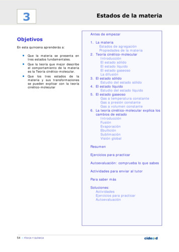
43Assembly ManualArduino Materia 101Board rXYour Materia 101 is assembled andready to be wired. You need only aflathead electrician’s screwdriver.Fig. 1In this step, we are going to wire rFig. 1ZYXEND-STOPsStepperEXTON/OFF
44Assembly ManualArduino Materia 101Board wiringFig. 2now connect the fans, paying closeStart with the wiring of the twoattention to the polarity (as pictured).displays. Take the ‘EXP1’ and ‘EXP2’Fig. 2Fig. 3connectors and insert them insideFig. 4each pin (they are marked on theNow connect the extruder’s stepperdisplay and on the board), orientedwith the correct polarity, as shownwith the tap looking to the board’sin picture. Now take the screwdriverborder. Now connect the end-stopsand start to connect the cable of the(3), paying attention to the polarityheating cartridge (red and grey but(as pictured). Last, we can connect thehave no polarity) into the slots locatedthermistor on the firsts two pins, asin the lower right corner, as shown inpictured. The polarity is not a problemthe picture. Finally, connect it, payingin this case.attention to polarity. The LED goes inthe same slot where we will connectFig. 3the power supply. The black cableNow move on to the X, Y and Z steppercoming from the wall socket goes intomotors’ wiring. They have also beenthe first top slot (negative) and the redmarked to identify them more easily.cable coming from the switch goesStarting from the first X stepperinto the slot below (positive).connector on the picture’s right, weconnect all three of them, payingclose attention to the orientation.Fig. 4If not connected like in the picture,the motors will run backwards. We
45Assembly ManualArduino Materia 101Board wiringFig. 5 - 6Order the wiring so it is not anobstacle to the board fan. Join themachine’s bottom wiring (Y stepper,Z stepper and Z end-stop cable) withcable ties. Lead them to the frame’sside, in the direction of the board.Fig. 5The excess part of the wiring shouldbe wrapped together with somecable ties. At this point, lead theLED cables to the front frame board.Now wrap the excess wiring of theextruder and of the X carriage. Usethe cable ties and position them onthe printer’s bottom.Fig. 6
Assembly ManualArduino Materia 10109Calibration46
47Assembly ManualArduino Materia 101CalibrationTake a look at the power supply’sadjusting the potentiometers and usewiring. If it is OK, turn it on! Now wea ceramic screwdriver.can look at a couple of things. If youFig. 1Fig. 2do not see “MATERIA 101” on yourFig. 2LCD panel, you need to upload theOn the display you will read “Materiafirmware onto your 3D printer. You101” and a thermistor temperaturecan download it here: http://arduino.next to the ambient one.cc/en/Main/ArduinoMateria101Fig. 3Fig. 1From the LCD menu select PrepareWhen the printer is on, the white-- Autohome : you see that X, Y e ZLEDs are also on. Take the multimetermotors will read every end-stop (X toand set it on the DC reading; placethe right, Y to the bottom, Z goes up).the black tip on the negative input(black). Place the red tip on theFig. 4stepper motor’s driver potentiometer.WhenPotentiometers are the small star-triggered, the back extruder motorshaped screws that you find onfan must turn on.the driver. To check the stepperdriver Vref, adjust the Vref with thefollowing values: X0.4 Y0.4 Z0.4 E0.5and adjust the potentiometers withFig. 3Fig. 4a small screwdriver. Be certain not totouch anything else conductive whentheautohomehasbeen
48Assembly ManualArduino Materia 101CalibrationFig. 5From the “Prepare” menu you canIf you choose Prepare -- Preheattry to launch the “Change Filament”from the LCD menu you will see thecommand; the printer will heat upLCD temperature going up and theand the axes will finding their homefrontal fan turning on.position. When the printer is at thecorrect temperature it will unloadthe filament. The extruder motorwill run clockwise with a beepingsound at the end. You must click theknob to stop it. Now the motor isrunning counter-clockwise. You caninsert a filament inside the extruderby using just a bit of pressure.IF YOU HAVE NOT ENCOUNTEREDANY PROBLEMS SO FAR, YOU AREDOING A GREAT JOB!Fig. 5
Assembly ManualArduino Materia 10110Shell and finishing49
50Assembly ManualArduino Materia 101Shell and finishingFig. 1Fig. 4You will need:Push the On/Off switch, from theprinter’sthe OFF position) to the right.— M3x10 bolts (8)— Washers (4)— ON/OFF switch sleeves— Control knob— M3 nuts (8)Fig. 2Paste on the Arduino Materia 101stickers as you see in the picture.Fig. 3Remove the wrapping from thefront case and begin putting it onthe printer and fasten it on withFig. 4outside,— Machine case kit— M3x6 bolts (36)Fig. 3theleaving the groove (which means— M10 screw with 2 M10 cap nutsFig. 2to— Pre-assembled and tested printer— Arduino Materia 101 sticker kitFig. 1insideM3x6 bolts (8).
51Assembly ManualArduino Materia 101Shell and finishingFig. 5Screw on the switch sleeve. Take theknob and insert it onto the display’spotentiometer.Fig. 6Fasten all the external covers.Fig. 5Fig. 6Fig. 7 - 8 - 9Take the two electronic part coversand insert them one at a time. Startfrom the bottom and make thecables pass into the appropriateslots, as in photo. Attach the twobulkheads, using the M3x10 bolts (4)and the 4 washers.Fig. 7Fig. 8
52Assembly ManualArduino Materia 101Shell and finishingFig. 10 - 11 - 12Assembling the spool holder.Using the M3x10 bolts (8) with theM3 nuts (8), assemble the spoolholder. Apply the Arduino’s stickeronto the back case. Insert the spoolthen the M10 threaded bar, securingFig. 9Fig. 10Fig. 11Fig. 12it with M10 cap nuts (2).
53Assembly ManualArduino Materia 101Shell and finishingBEFORE THE FIRST PRINT:should hear a noise like a “tak taktak”). Be careful not to tighten theFig. 13springs too much: this will cause aLubricate the Z lead screw withloss of steps to the motors and grindsewing machine oi
Materia 101 is designed by Sharebot for Arduino. 08 - Board wiring 09 - Calibration 10 - Shell and finishing 42 46 49 INDEX 00. INTRODucTION 01. Assel Maal 4 Arduino Materia 11 We are excited that you have decided to take part in this new industrial revolution. Like all new technology, it is pioneers like