Transcription
Rev: 04.02.131-888-628-1730 Mini Maxx Installation Manual1
Revision DateThese instructions are current as of 04/02/13. Revisions may apply, and are available atwww.hsperformance.comWarning!THIS IS A HIGH PERFORMANCE PRODUCT TO BE USED AT YOUR OWN RISK!Do not install this product until you have read and fully understand the following disclaimer of liability. The following disclaimer of liability sets forth the terms and conditions for the installation and/or use of this product. Byinstalling this high performance product, the buyer acknowledges that they have read and fully understand thisdisclaimer and accepts its terms and conditions.DISCLAIMER OF LIABILITYH&S Performance, LLC and their successors, distributors, jobbers, dealers, and retailers (SELLER) shall in no way be responsible for any direct, indirect, or consequential damage resulting from improper installation and/or use of this product. TheBUYER/USER assumes all responsibility for any damage resulting from the use or misuse of this product The buyer herebywaives all liability claims for the use of this product.The BUYER acknowledges that he/she is not relying on the SELLER’s skill or judgment to select or furnish goods suitable forany particular purpose and that there are no liabilities which extend beyond the description herein, and the BUYER herebywaives all remedies or liabilities, expressed or implied, arising by law or otherwise, (including without any obligations of theSELLER with respect to fitness, merchantability and consequential damages) or whether or not occasioned by the SELLER’snegligence.The SELLER disclaims any warranty and expressly disclaims any liability for personal injury or damages. The BUYER acknowledges and agrees that the disclaimer of any liability for personal injury is a material term for this agreement and the BUYERagrees to indemnify the SELLER and to hold the SELLER harmless from any claim related to the product purchased. Under nocircumstances will the SELLER be liable for any damages or expenses by reason of use or sale of any such products.The SELLER assumes no liability regarding the improper installation, misuse, or misapplication of its products. It is the buyerand/or installer’s responsibility to check for proper installation.INTERNET UPDATES:H&S Performance regularly issues free internet updates and custom tunes for the Mini Maxx. Pleasecheck to see if there are any available for your truck by going to the updates section at:www.hsperformance.comTROUBLESHOOTING:Please read and understand all installation instructions before proceeding with the installation.If you have questions during the installation of this product, please call H&S Performance support at1-888-628-17302Mini Maxx Installation Manual www.hsperformance.com
LIMITATION OF WARRANTYH&S Performance, LLC (“SELLER”) gives Limited Warranty as to the description, quality, merchantability, fitness for any product’s purpose, or any other matter of SELLER’s product sold herewith. The SELLER shall be in no way responsible for the product’s use and service and the BUYER hereby waives all rights other than those expressly written herein. This Warranty shall notbe varied except by a written agreement signed and dated by SELLER and BUYER.The Warranty is Limited to one (1) year from the date of sale and limited solely to the parts contained within the product’soriginal packaging. All products that are in question of Warranty must be returned shipping prepaid to the SELLER and mustbe accompanied by a dated proof of purchase receipt. All Warranty claims are subject to approval by H&S Performance, LLC.Under no circumstances shall the SELLER be liable for any labor charges incurred, or travel time incurred in diagnosis fordefects, removal, or re-installation of this product, or any other contingent expenses. Any product deemed defective andconsequently repaired or replaced by SELLER, shall retain the remainder of the warranty period from date of purchase, as thewarranty period shall not be extended due to repair or replacement. Under no circumstances will the SELLER be liable for anydamage or expenses incurred by reason of the use or sale of any such product.-This warranty is null and void after 90 days for an unregistered /-This warranty is null and void for any new products purchased through unauthorized /-This warranty is null and void for any products sold as USED or REFURBISHED.-This warranty is null and void for any products purchased below the H&S UNILATERAL PRICING POLICYwww.hsperformance.com/pricing-policies/-This warranty is null and void for any products that have been altered by a 3rd party.If the buyer does not agree to the terms of this limited warranty or the disclaimer of liability, the buyer may return this productto the SELLER in a new and unused condition, along with dated proof of purchase, within 30 days of purchase, for a full refund.To register your product online, visit www.hsperformance.com/register or scan the QR code.Benefits to registering your product include: Guarantee full warranty coverage. Get entered into drawings for free H&S products and prizes. Get notified of software updates and upcoming features.1-888-628-1730 Mini Maxx Installation Manual3
TABLE OF CONTENTSBILL OF Materials. 5Parts DESCRIPTIONS. 6Mini Maxx INSTALLATION. 9Section 1: Mounting the Mini Maxx.10Windshield Mounting.10Section 3: OBD II Adapter plug.11Section 4: Installing the Power Wire.12Section 5: Run Mini Maxx HDMI Cable.13Mini Maxx Operation. 14Section 1: Button Navigation.14Section 2: Install Download.15Section 3: Exploring the Main Screen.16Section 4: Exploring the Menu System.18Section 5: Vehicle Setup.19Defueling Parameters.19Set Defuel Levels.20Section 6: Other Mini Maxx Features.21Gauge Setup.21Adjust Backlight.22Change Background Color.22Performance Testing.23Diagnostics.24Reset to Default Setting.25Show Settings.26T.V.#.26SD Card.26Web Updates.26Section 7: USA / ULSD Calibration Vehicle Specific Features.272006-2007 5.9L Dodge Cummins.272007.5-2009 6.7L Dodge Cummins.302010-2012 6.7L Dodge Cummins.332003-2007 6.0L Ford Powerstroke.362008-2010 6.4L Ford Powerstroke.372011-2013 6.7L Ford Powerstroke.402007.5-2010 6.6L LMM Duramax.422011-2013 6.6L LML Duramax.45Section 8: High Sulfur Calibration Vehicle Specific Features.482007.5-2009 6.7L Dodge Cummins.492010-2012 6.7L Dodge Cummins.512008-2010 6.4L Ford Powerstroke.532011-2013 6.7L Ford Powerstroke.552007.5-2010 6.6L LMM Duramax.572011-2013 6.6L LML Duramax.584Mini Maxx Installation Manual www.hsperformance.com
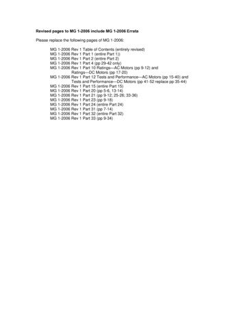
Bill of MaterialsThe list below includes by name the major parts included in your Mini Maxx package.1. 2.Mini MaxxMicro SD Card(in Mini Maxx)Mini Maxx Power Cable3.4.5.6.7.OBD II AdapterWindshield MountMini USB CableHDMI CableUSB Adapter1.2.3.4.5.6.7.1-888-628-1730 Mini Maxx Installation Manual5
Parts descriptionThis section describes each of the parts in the Bill of Materials, the descriptions provide a physical set ofattributes and a purpose for each part. The parts descriptions also list everything that is included in eachassembly.The Mini Maxx Head UnitThe main component is the Mini Maxx Head Unit. The HeadUnit is the interface in which you control vehicle performance parameters. It is also the brains that will save vehicleactivity and defuel a vehicle. Notice that the head unit has:seven total buttons, five on the left side and two on the right,a large color screen, and an electronic plug for docking onthe back. Note that this is the last piece that you will install.Note: Mini Maxx includes a micro SD card insertedin the side of the Head Unit.Power CableThe Power cable connects the OBD ll Adaptor Plug to the vehicle fuse box to supply power to the Mini Maxx. It is optionalto use as there are two ways to power up your Mini Maxx1.(Recommended) Use this power cable and wire it to thedesignated location specified later in this manual.2.The OBD II port provides constant 12V power, so your Mini Maxx can power off of the OBD IIport alone. But in this situation the Mini Maxx will not turn on and off with the ignition. There isa switch on the OBD II adapter plug in order to turn the Mini Maxx on and off.6Mini Maxx Installation Manual www.hsperformance.com
OBD II Adapter PlugThe OBD II Adapter is a communication hub for the Mini Maxx.The OBD ll Adaptor plugs directly into the vehicle OBD ll port.Notice the OBD ll Adaptor has many ports to support variousother functions of the Mini Maxx.Universal Windshield MountThis universal windshield mount is used to install theMini Maxx firmly onto the windshield, it is a suctioncup mount that will work on any vehicle windshield.Check our web site for other mounting options, theMini Maxx is adaptable to a range of other mountingstyles.H&S Also offers custom vehicle specific solutions. See www.hsperformance.com for details.1-888-628-1730 Mini Maxx Installation Manual7
PARTS DESCRIPTION CONTINUEDMini USB CableUse this cable to connect your Mini Maxx to your personal computer to install software updates. Visitwww.hsperformance.com in the downloads section for product updates. Please find your product application and follow the posted instructions there to update your Mini Maxx.HDMI CableThe HDMI Cable connects the Mini Maxx to the OBD ll Adapter Plug and acts as the main line of communication for the Mini Maxx.USB to Micro SD AdapterThe USB to Micro SD Adapter is what you will use to update your Mini Maxx. You will take the MicroSD card out of the Mini Maxx and insert it into the adapter, then insert the adapter into your personalcomputer.8Mini Maxx Installation Manual www.hsperformance.com
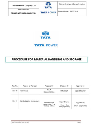
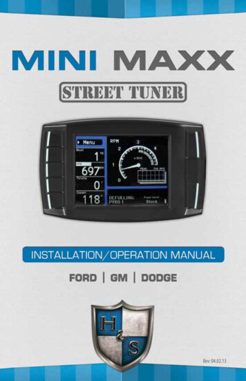
Installation OverviewThe installation overview illustrates a totally installed and functional Mini Maxx system. This overview ismeant to help reference the general location of installed parts and pieces of the Mini Maxx. Notice that thereare different overview diagrams. Use the correct diagram for your truck. For more complete wiring diagramsand instructions, please see vehicle specific features starting on page 27.most applicationsMini Maxx & Windshield MountFire wall grommetFuse BoxPow(Op er Cabtion leal)OBD II Adapter PlugOBD II PortFORD POWER STROKE ‘08-’10MINI MAXX &Windshield mountHDMI CableOBD II PortOBD II Adapter PlugPower Wire(Optional. To purpleignitionwire under dash)1-888-628-1730 Mini Maxx Installation Manual9
INSTALLATION CONTINUEDMini Maxx Installation InstructionsSection 1: Mounting the mini maxxIn this section you will decide where to mount the Mini Maxx Cradle, so you are essentially choosing the location for the Mini Maxx inside the vehicle cab. First, decide which mounting style you will choose for the MiniMaxx; we offer two different styles of mounting:1. Windshield mounting2. Custom Pod mounting (Refer to the instructions included with your custom pod)Visit www.hsperformance.com for custom optionsWindshield Mounting1. Locate the T-shaped mount socket on the back side of the Mini Maxx.2.Notice that the top of the universal mount will fit into T-shaped socket and slide forward tosecure the Mini Maxx to the mount.3.With the Mini Maxx connected to the mount use the windshield mount to secure the Mini Maxxto the wind- shield. Be sure that the position of the Mini Maxx does not obstruct the view ofthe road or distract the driver from their primary responsibility, which is driving responsible.10Mini Maxx Installation Manual www.hsperformance.com
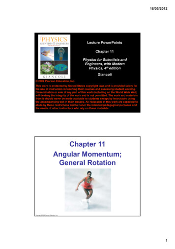
Section 2: OBD II Adapter plugThis step involves locating the vehicle’s OBD ll port andthen simply plugging the OBD ll Adapter Plug into theOBD ll port.1. As the illustration below shows, OBD ll portsare always located somewhere under the drivers side dash. The OBD ll port is a male receiverthat will have the same shape as the end of theOBD ll Adaptor plug.2. Once the OBD ll port is located, then simplyplug the OBD ll Adaptor plug into the OBD llport.Possible OBDII Port Locations(location may vary)OBD II Adapter plug diagram1. OBD ll Male end: this is the part of the adapter plug that plugs into the vehicle OBD ll port.2. Main harness port: the main harness will plug into the Mini Maxx and into this port during installation.3. Power wire port: the power wire will run from this port to the vehicle fuse box during installation.Plug into the Mini Maxx and into this port during installation.4. Power supply switch: use this switch to change power from battery power to keyed power for apowered supply for the Mini Maxx.5. Four pin usb: This port is used if an H&S pyrometer kit is purchased for the Mini Maxx.6. Five pin usb567. Adapter plug fuseKEY BATT24731Note: On some vehicles it is recommended to move the OBD II port to a safer location. Because the Mini Maxx willremain plugged in, the adapter can be kicked/bumped and broken. Please move your OBD II connection to a saferlocation if you feel it is in a position that may allow it to get damaged.1-888-628-1730 Mini Maxx Installation Manual11
Section 3: Installing the Power Wire (*Optional)*The OBD II port provides constant 12V power, so your Mini Maxx can power off of the OBD II port alone.But in this situation the Mini Maxx will not turn on and off with the ignition. There is a switch on the OBD IIadapter plug in order to turn the Mini Maxx on and off.In this section you will run the Power Wire coming from the Mini Maxx Cradle to the vehicle fuse box andconnect it to the fuse locations specified below. The fuse location for the Power Wire is different on eachvehicle application.CONNECTING THE POWER WIRE:1. Route wire to location shown in pictures found in the Vehicle Specific Sections starting on page 272. Remove the fuse, indicated in the pictures, and insert the fuse jack. Make sure that the fuse jack is placedon the dead side of the fuse to ensure that the Mini Maxx is protected by the fuse. Use a volt meter to verifythe dead side of the fuse. With the fuse pulled and the truck powered on but not started, the volt metershould read 0 volts on the fuse jack to ground. Problems that can occur if the incorrect fuse is used forthis connection: the power may stay on continuously even with the key off; or, the Mini Maxx can receivepower at the incorrect time of the power-on/starting cycle of the vehicle.3. Run the power wire through the fire wall before preparing the Power Wire. Prepare the Power Wire bystripping the end of the wire about ¼”. Connect the blue 90 connector to the end of the Power Wire usingcrimping pliers.4. Connect the Power Wire to the fuse jack, place the fuse back into the slot, and close the fuse box.12Mini Maxx Installation Manual www.hsperformance.com
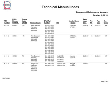
INSTALLATION CONTINUEDSection 4: Run Mini maxx hdmi cableIn this section you will connect the Mini Maxx HDMI cable to the OBD ll Adaptor plug and then run the otherend of the HDMI cable up the side of the vehicle dash and connect it to the back of the Mini Maxx.1. Plug one end of the HDMI cable into the Main Harness port on the OBD ll adapter plug.2. Run the other end of the HDMI cable up through the vehicle dash on the drivers side so that the end ofthe cable emerges from the dash near the vehicle A-pillar. It may be necessary to temporarily removethe vehicle weather stripping and dash panel to achieve an installation where the HDMI cable cannotbe seen.3. Plug the HDMI cable into the back side of the Mini Maxx, make sure that there is enough slack in thecable to accommodate mounting the Mini Maxx to the windshield.Mini MaxxHDMI CablePower CableOBD II PlugAlmost Done!You need to install the download now. Read the next section for Install Download procedure.1-888-628-1730 Mini Maxx Installation Manual13
Mini Maxx OPERATING INSTRUCTIONSThese operating instructions are split into sections: Section 1: Button Navigation Section 2: Install Download Section 3: Exploring the Main Screen Section 4: Exploring the Menu System Section 5: Vehicle Setup Section 6: Other Mini Maxx Features Section 7: Vehicle Specific Features Section 8: Unplugging the Head UnitSection 1: BUTTON NAVIGATIONPress the top left button to enter the Main Menu, also use this button to exit menus.SpeedMPHPress any of the four buttons on the left toselect items on the screen that are adjacent tothe button position.14In general these buttons work as up and downbuttons, they may also be used to select itemson the screen adjacent to these buttons.Mini Maxx Installation Manual www.hsperformance.com
Section 2: Install DownloadThe Install Download option is used to install tuning onto a vehicle, or return a vehicle to stock.1. Press Menu: To get into the Mini Maxx main menu.2. Select Install Download: You may have to “Arrow Down” or “Arrow Up” to find this option.3. Install a download onto a stock vehicle: If the vehicle is stock and you enter the install downloadmenu, simply follow the screen prompts to install a download on the vehicle. This is the point in which youmay come across the tire size calibration menu, and the vehicle speed limiter menuDownload H&S Tuning: This option will install the H&S Performance tuning to your truck. Customtuning options can be downloaded from H&S or may be available as options during the installationprocess.Import/Export MCC Tuning: This option will allow import or export of MCC software tuning files.Some vehicle may not have this option. See www.hsperformance.com/mcc for more info.Return to stock (OEM tune): This option will return the vehicle to its factory software level and unlock the H&S device. This is highly recommended if taking the vehicle in for service or maintenance.NOTE: Returning to stock is required in order to install your tuner on another vehicle.Go Back(RESET)DOWNLOAD MENUDownload H&S TuningImport/Export MCC TuningReturn to Stock (OEM Tune)This Mini Maxx screen shot shows what you will see if a download has already been entered into a vehicle.Before installing the download: Make sure that the Mini Maxx is properly plugged in. Make sure that the harness is properly installed. The vehicle battery is fully charged. The vehicle is warmed up to operating temperature.THE micro SD CARD MUST BE INSERTED IN THE SIDE OF THE MiniMaxx TO Download to a vehicle.1-888-628-1730 Mini Maxx Installation Manual15
Mini Maxx OPERATION CONTINUEDSection 3: exploring the main screenThe Main Screen is where you view all of the vehicle activity. In this section you will learn how to navigatethe Main Screen and learn about all of the different parts of the Main Screen.Main screen navigationBelow are descriptions of how all of the Mini Maxx buttons work and what they do while in the MainScreen. The buttons perform different functions while in a menu or submenu.Press the top left button to enter the Main Menu, also use this button to exit menus.MenuSpeedRPMThrottleCoolantMPHXºFPress any of the four buttons on the left thatcoincide with the four vehicle parameters todisplay that particular vehicle parameter on thelarge gauge in the upper right side of the screen.Hold a button down to view the different graphtypes for the large gauge.1660MPHRPM90120300Power Level Settingnot available untildownload is installed.Power Level UpPower Level DownUse the power level buttons to control powerlevels on-the-fly only while in the main screenMini Maxx Installation Manual www.hsperformance.com
Main screen Parts descriptionThis section will describe all of the different parts of the Main Screen.The black bar: The black bar highlights the title of one of the four displayed vehicle parameters to indicatethat vehicle parameter is also being displayed on the large gauge.Menu button: press to enter the main menu.MenuSpeedRPMThrottleCoolantLarge GaugeMPHMPHRPMXºF9060120300Power Level Settingnot available untildownload is installed.Vehicle parameters: To change which vehicleparameter is displayed in the large gauge areasimply press one of the four buttons next thepreferred vehicle parameter.By pressing and holding the button next to yourdisplayed gauge, you can change the displaystyle in the large gauge area.Power level text: Displays which power level isactive, whether it be: Stock, Tow, Street, or Hot.Note: This will not be active if the Download hasnot been installed.1-888-628-1730 Mini Maxx Installation Manual17
Mini Maxx OPERATION CONTINUEDSection 4: exploring the menu systemThe diagram below shows all of the Main Menu items and explains the Main Menu navigation.This button is used to enter into the Main Menufrom the main screen. While in any of the menusthis button works as a back button.Go Backto Main ScreenNavigation through the main menu: Use thelarge Up Down Buttons to page up andpage down through all the Main Menu options.MAIN MENUInstall DownloadGauge Set UpSet User OptionsSet Defuel LevelsAdjust Tire SizeDiagnosticsShow SettingsThese buttons are usedto enter into the submenus from the mainmenu and may also beused to select additionalitems when in the submenus.18Update FirmwareMini Maxx Installation Manual www.hsperformance.com
INSTRUCTIONS CONTINUEDSection 5: Vehicle SetupThis section describes various non-vehicle specific features of the Mini MaxxDefueling ParametersSet up defueling parameters based on a number of different vehicle parameters. In this menu youcan also turn vehicle parameters off. The defueling parameters available are vehicle specific, so notall defueling parameters are available for every make and model.GoBackto Main MenuDEFUEL MENUPyro 1 Temperature LevelSetting: 600 FPyro 2 Temperature LevelSetting: 1250 FEngine Coolant Temp LevelSetting: 210 FBoost LevelSetting: 23PSITransmission TemperatureSetting: 260 FOil TemperatureSetting: 210 FPress to enter set up menu for defuel items.Current setting are displayed in Defuel MenuDefault Defueling SettingsPyro 1 Temperature Level1450 FPyro 2 Temperature LevelOFFEngine Coolant Temp Hot210 FEngine Coolant Temp Cold (cold start protection) OFFBoost LevelOFFTransmission Temp LevelOFFOil TemperatureOFFUse the Up Down Buttons to scroll up anddown through the different sub menu items.Here is a list of all of the defueling capabilitiesfor the Mini Maxx. All defueling options can beactivated at the same time, all can be turned off,or a mix of on and off. Each defueling option isadjusted individually to be on or off and set to aparticular defueling temperature.1-888-628-1730 Mini Maxx Installation Manual19
Set Defuel LevelsWhen entering a setup menu for any of the defuel options the menu will have a list of defuel levelsto select from based on that specific defuel parameter. The selected value is displayed on the left, toselect a defuel level you need only highlight the amount and then exit the setup menu. To turn anyparticular defuel parameter off press the bottom left button.GoBackto Defuel MenuThe selected Defuel valuefor PYRO 1 is displayedin the box below:Selected1400º FDEFUEL ONPYRO1Set Deful LevelDefueling Levels125013501400145015001550DEFUEL OFFUse this button to turn the defueling on.GoBackto Defuel Menuup13001600downUse the large Up Down Buttons to scroll upand down through the different sub menu items.PYRO1Set Deful LevelThe selected defuel valuefor PYRO 1 is displayedin the box below:SelectedOFFDEFUEL ONDEFUEL OFFUse this button to turn the defueling off.20Mini Maxx Installation Manual www.hsperformance.com
Section 6: Other Mini Maxx FeaturesThis section describes all the customizing features of the Mini Maxx.Gauge SetupEnter to change the vehicle parameters displayed on the four gauge locations in the Main Screen. This isalso where you can see all of the most up-to-date vehicle parameters available to your vehicle make andmodel after running an internet upgrade.Selecting a vehicle parameter to display in a particular location is done by highlighting the gauge location andthen highlighting the desired vehicle parameter.Once the correct vehicle parameter for a gauge location has been highlighted, you do not need to press anotherbutton to select that vehicle parameter. Simply highlighting the vehicle parameter makes it active in that location.Notice that upon entering the gauge setup menu that, Set Gauge 1, is highlighted in black. When a gaugelocation is selected it is highlighted in black on the left and it also appears above the vehicle parameterselection box.GoBackto Main MenuGAUGE SETUPSet Gauge 1Gauge 1SpeedSet Gauge 2Use the Up and Down Arrowsto Change the Gauge FunctionRPMSet Gauge 3ThrottlePyro 2SpeedBoostSet Gauge 4CoolantTo highlight a different gauge location press theselection button that coincides with that gaugelocation. So to select gauge location 1, press thesecond button down on the left hand side of theMini Maxx. To select the 4th gauge location pressthe bottom button or the 5th button down onthe left side.Use the large Up Down Buttons to highlighta particular vehicle parameter for any of thegauge locations.1-888-628-1730 Mini Maxx Installation Manual21
Adjust BacklightHighlight screen and use the up and down buttons to adjust the lighting to your preference.Go Backto User OptsScreenBACKLIGHTINGUse thesebuttons toadjust thebacklightbrightnesslevel.Screen BacklightBrightness 100%Select 0 to 100% using andto set desired light level050100Use this button select the ‘Screen’ option.Change Background ColorUse the up and down buttons to select a background color. The Mini Maxx background willpreview each color background as you scroll up and down through the color opti
to use as there are two ways to power up your Mini Maxx 1. (Recommended) Use this power cable and wire it to the designated location specified later in this manual. 2. The OBD II port provides constant 12V power, so your Mini Maxx can power off of the OBD II port alone. But in this situ