Transcription
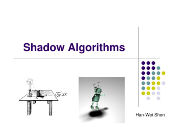
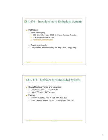
CSE 167 (FA 2021) Shadow Mapping. Final project expectations,guide and hintsIn this final project topic, we implement shadows in OpenGL using the aid of texture. In essentialidea is presented in the slides of 10/29. Bonus credits will be given if you also implement theperspective warping of the light space to rearrange the light space resolution to reduce aliasing.ExpectationYou will present a scene (like HW3) with shadows from at least one light source. The light sourcecan be a distant light (light at infinity) or a point light.While bonus credits will be given as long as you have excellent exposition and demonstration,one possible direction to get bonus is to implement one of the methods of Perspective ShadowMaps (PSM)1 , Light Space Perspective Shadow Maps (LiPSM)23 , Trapezoidal Shadow Maps(TSM)4 . All of these methods take advantage of a perspective transformation to rearrange thedensity of the light rays so that we have less pixelated effect on the edge of the shadow.Figure 1 An example of demonstrating having shadows in the scene.BasicsThe shadow mapping technique requires two rendering passes. That is, in the display callbackfunction, we will call draw scene twice. However, the two rendering are set with two differentcameras and different shaders. In the first rendering, the camera is at the light responsible for casting shadows. In the second rendering, the camera is placed at the actual camera, forming the final image.Each of the two cameras has a camera matrix C, view matrix V (inverse of the camera matrix)and a projection matrix P. Let us them Clight , Vlight , Plight and Ccam , Vcam , Pcam respectively.In the first pass of rendering (using Vlight , Plight ), we product an image whose pixel valueis the depth of the scene. This depth can be the Z value after the multiplication by Plight (anddehomogenized (divided by the w coordinate)). That is, the Z value in light’s normalized devicecoordinate. The depth value can also simply be the physical distance between the light (eye oflight) and the fragment position.1 erspectiveShadowMaps.pdf2 Originalpaper dows egsr2004revised.pdf3 Sec3.2.2 of the course note dowcourse-eg10.pdf4 https://www.comp.nus.edu.sg/ tants/tsm/tsm.pdf1
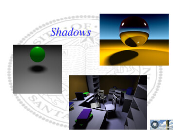
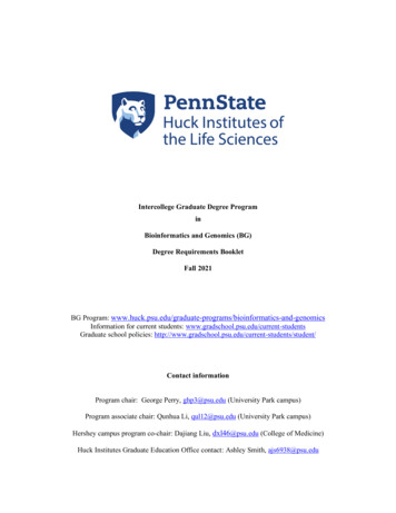
Figure 2 Two pass rendering. The first rendering from the light records the distance fromthe geometry to the light. The second rendering is the final image whose color isevaluated using information sampled from the first image.Now, store this first pass rendering result in a texture.5 Of course, as you develop the program,you may want to visualize this first pass rendering. In that case you can show it on the screen forthe visualization purpose.In the second pass of rendering (using Vcam , Pcam ), render it as usual (like in HW3). Theonly difference from HW3 is in the fragment shader where we shade the color. If n · l 0, the surface is already facing away from the light, so we don’t need to invokethe shadow technique. If n · l 0, then we check whether we are in the shadow or not:– Transform the fragment position to the light’s normalized device coordinate (multiply by Plight Vlight , dehomogenize). This is the coordinate of the fragment in the 1stpass image.– Note that the texture coordinates range in [0, 1] [0, 1], whereas the XY coordinatein the normalized device coordinate has the range of [ 1, 1] [ 1, 1]. A simplerescaling is needed.– Sample the depth that was recorded in the texture.– Also compute the depth value of the current fragment. If the depth value wascomputed by the physical distance between the light and the fragment, then do thesame calculation for this fragment.– If the sampled depth is (much) shorter than the new depth value, then we have ashadow. Add contribution of the light only when it is not under the shadow. An exception is theambient component of the lighting. Without a bit of ambient shading, the shadow wouldlook pitch black.5 orials/tutorial-14-render-to-texture/ for direct rendering into a texture buffer.2
Implementation TipsWe recommend you to implement this project by extending your HW3 code. Here’s a short listof necessary modifications needed to be taken care of: In main.cpp:– Add a depth rendering pass to display(). In include/:– Derive a DepthShader structure from Shader. In include/light.h:– Augment the Light structure to store shadow map texture / buffer object. In Scene.cpp:– Augment or add a draw() method to handle shader swapping on demand. In Scene.inl:– Add a ground plane to the scene so that the shadow effect could be better observed. In shaders/:– Add a lightspace.vert vertex shader, which transforms vertices to light space.– Add a depth.frag fragment shader, which writes depth information to fragments.– Augment lighting.frag to incorporate shadow computations. Specifically, you’llappend a uniform sampler2D shadowMap; texture sampler to sample the depth map,and pass in an additional fragCoord in light space.Next is how to setup the depth map and its corresponding frame buffer object. Here’s a quickrundown of the procedure:1. Generate a frame buffer object.GLuint depthMapFBO;glGenFramebuffers(1, &depthMapFBO);2. Create a 2D texture for the depth map.const GLuint SHADOW WIDTH 1024, SHADOW HEIGHT 1024;GLuint depthMap;glGenTextures(1, &depthMap);glBindTexture(GL TEXTURE 2D, depthMap);glTexImage2D(GL TEXTURE 2D, 0, GL DEPTH COMPONENT,SHADOW WIDTH, SHADOW HEIGHT, 0, GL DEPTH COMPONENT,GL FLOAT, NULL);glTexParameteri(GL TEXTURE 2D, GL TEXTURE MIN FILTER, GL NEAREST);glTexParameteri(GL TEXTURE 2D, GL TEXTURE MAG FILTER, GL NEAREST);glTexParameteri(GL TEXTURE 2D, GL TEXTURE WRAP S, GL REPEAT);glTexParameteri(GL TEXTURE 2D, GL TEXTURE WRAP T, GL REPEAT);3. Attach depthMap to depthMapFBO’s depth buffer:glBindFramebuffer(GL FRAMEBUFFER, depthMapFBO);glFramebufferTexture2D(GL FRAMEBUFFER, GL DEPTH ATTACHMENT,GL TEXTURE 2D, depthMap, 0);glDrawBuffer(GL NONE); // Omitting color dataglReadBuffer(GL NONE); // Omitting color dataglBindFramebuffer(GL FRAMEBUFFER, 0);3
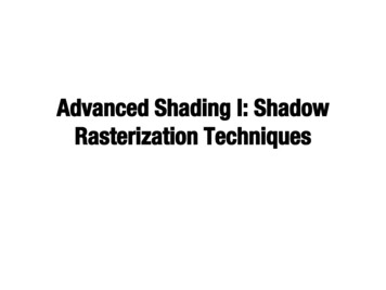
Implementing a project of this size can easily get you lost, so here’s a few checkpoints we’vecurated to help you stay on the right track:1. Get your depth shader ready. Once you’ve finished the additional shader implementation.Compile them and use their shader program to render the scene from main camera. Itshould produce something like this:Tip: If yours looks all white, scale the depth down by 0.1, or remap it using a nonlinear function.2. Check your light space transformations are all good. Hotwire your render pipeline inmain.cpp to output whatever your light is seeing.Tip: Viewport is expected to look clamped if your shadow map has higher resolution than screen.3. Before final lighting computation, check if depth from the depth map is correctly passedin. A common trick to debug shader is to convey information in colors. You can viewthis from your main camera, simply let fragColor vec4(vec3(depthSampled), 1.f);.You should see something like this:4
Tip: Artifacts at greasing angles from light’s perspective are results of z-fighting.One more thing to mention, Shadow acne: if you’re getting something like this:This is a common shadow mapping artifact called shadow acne. It is a type of aliasingartifact due to limited resolution of the shadow map, such that discretized depth valuesundersamples actual depth information and causing disagreement between the shadowmap and lightspace fragment coordinates during occlusion test. This can be resolved byintroducing a slight bias to the sampled depth from the shadow map:float bias max(0.05 * (1.0 - dot(normal, lightDir)), 0.005);float shadow LSDepth - bias sampledDepth ? 1.f : 0.f;5
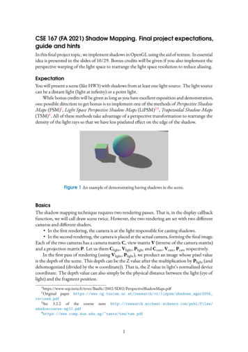
Lastly, here’s a reference "solution" for you to comapre with:AdvancedAs you can see in Figure 1, the edges of the cast shadows have lego/pixelated boundary. Thisis due to the finite resolution of the image of the first pass rendering. You are encouraged towork on a solution to this problem using a projective transformation. (The principle of shadowsis invariant under collinear transformation. As long we map straight lines to straight lines likein projective transformation, the resulting light-visibility will be the same, but with differentdistribution of resolution!)There are two ways one can perform projective transformation without messing up the lightdirections: Work in the normalized device coordinate (NDR) of the camera. (Perspective shadowmaps, or PSM) Work in the normalized device coordinate of the light. (Light space perspective shadowmaps, or LiSPSM)In these post-perspective coordinates, the light rays from either the camera or the light will beparallel to the Z axis. This somewhat makes analysis easier.In PSM, we can just set up the light (i.e. its view matrix and projection) in camera’s NDR.In this coordinate system, objects closer or further from the camera will be of the same size, andthus we have a more evenly spread resolutions. Pretending the world space is NDR, we need towork out the eye position, target, etc. of the light. The rest is the same as the basic shadow map.In LiSPSM, as shown in Figure 6, one performs a perspective transformation in light’s space.One must choose this additional transformation so that the rasterizer’s Z direction remain thesame. The remaining X and Y can be tapered and non-uniformly rescaled to gain more resolutioncloser to the camera.6
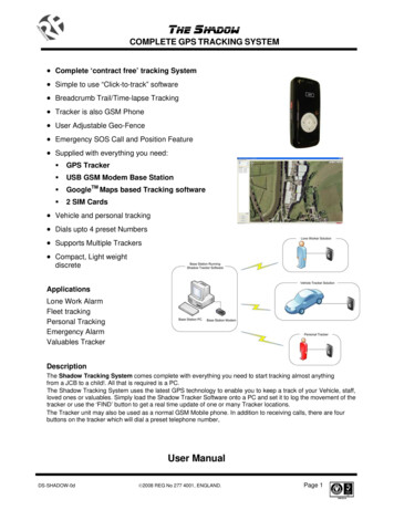
Figure 6 In Light Space Perspective Shadow Map (LiSPSM), one performs an additionalperspective transformation on (c) light’s normalized device coordinate (NDR) toget (d) a new light’s NDR. In the new light’s NDR, the Z axis remains the sameso that the rasterization visibilities are equivalent. However, the density of pixel isrearranged (red vs orange) so that we have more light-space pixel resolution closerto the camera.7
If n ·l 0, the surface is already facing away from the light, so we don’t need to invoke the shadow technique. If n ·l 0, then we check whether we are in the shadow or not: – Transform the fragment position to the light’s normalized device coordinate (multi-ply by P light