Transcription
Wire Harness Installation InstructionsFor Installing Harness Numbers:60221: 03 – 06 GM Gen III 4.8/5.3/6.0L EFI Harness - Throttle by WireManual P/N 90570Painless Performance Products recommends you, the installer, read thisinstallation manual from front to back before installing this harness.1
Painless Performance Products, LLC2501 Ludelle St.Fort Worth, TX 76105-1036PHONE: 800-423-9696 FAX: 817-244-4024EMAIL: support@painlessperformance.comIf you have any questions concerning the installation of this harness,feel free to call Painless Performance Products' Tech Line at 1-800-4239696. The Tech Line can be reached from 8 A.M. to 5 P.M. central time,Monday through Thursday, and 8 A.M. to 4:30 P.M. on Fridays.We have attempted to provide you with as accurate of instructions aspossible and are always concerned about corrections or improvements thatcan be made. If you have found any issues or omissions, or simply havecomments or suggestions concerning these instructions, please write us atthe above address, send us a fax at (817) 244-4024, or email us atsupport@painlessperformance.com. We sincerely appreciate your business.Painless Performance Products, LLC shall in no event be liable incontract or tort (including negligence) for special, indirect, incidental, orconsequential damages, such as but not limited to, loss of property damage,or any other damages, costs or expenses which might be claimed as theresult of the use or failure of the goods sold hereby, except only the cost ofrepair or replacement.3rd Edition: July 2021Copyright 2019 by Painless Performance Products, LLCCAUTION: BEFORE THE REMOVAL OF YOUR ORIGINALHARNESS AND/OR THE INSTALL OF YOUR NEW PAINLESSHARNESS, DISCONNECT THE POWER FROM YOUR VEHICLE BYREMOVING THE NEGATIVE OR POSITIVE BATTERY CABLE FROMTHE BATTERY.2
TABLE OF CONTENTSPAGE M PROGRAMMINGTOOLS NEEDEDKIT CONTENTSPRE-INSTALLATION AND HARNESS ROUTING GUIDELINESHARNESS ATTACHMENTGROUNDING THE VEHICLEINSTALLATION INSTRUCTIONSFUSE BLOCK, ECM, TAC MODULE, PEDAL MOUNTING ANDCONNECTIONSDASH PORTION; INFORMATION & INSTALLATIONENGINE CONNECTIONTAIL/TRANSMISSION GROUP INSTALLATIONTRANSMISSION FUNCTIONCONVERTING THE 4L60E TRANSMISSION CONNECTOR TO A 4L80ECONNECTORCONCLUSIONTHINGS TO REMEMBERRETRIEVING TROUBLE CODES FROM THE COMPUTERTROUBLE SHOOTING GUIDE FOR YOUR PAINLESSPERFORMANCE HARNESSLIMITED WARRANTY AND RETURN POLICYLIST OF FIGURESPAGE #SECTIONFIG. #6CONTENT OF THE 602219ACCELERATOR PEDAL9TAC MODULE CONNECTIONS10DATA LINK CONNECTOR10CRUISE CONTROL11BRAKE SWITCH CONNECTIONS11BRAKE SWITCH RELAY12’03 & ’04 KNOCK SENSOR CONNECTION13CRANKSHAFT POSITION SENSOR14CAM PROSITION SENSOR14MAP SENSOR14DRIVER SIDE COIL CONNECTOR14PASSENGER SIDE COIL CONNECTOR15ECT SENSOR15ALTERNATOR15MAF/IAT SENSOR16INJECTORS 1, 3, 5, & 7Continued 31234567891011121314151617
LIST OF FIGURESPAGE #16181919192022SECTIONFIG. #INJECTORS 2, 4, 6, & 8PARK/NEUTRAL POSITION SWITCHVSS SENSOR (4L60E)VSS & INPUT SPEED SENSOR, TRANSMISSIONCONNECTION (4L80E)4L60E/65E TRANSMISSION CONNECTIONTRANSMISSION CONNECTOR PIN-OUTNOID LIGHT181920214222324
INTRODUCTIONYou have purchased what we at Painless Performance Products believe to be the mostup-to-date and easiest-to-install automotive fuel injection harness on the market. It is designedfor easy installation, even if you have no electrical experience.This harness is designed to be a complete wiring system for the fuel injection system usedon General Motors 2003 - 2006 4.8L, 5.3L, & 6.0L Electronic Throttle, also known as Throttle byWire or Fly by Wire, engines and to control the 4L60E, 4L65E, 4L80E, 4L85E automatictransmissions. This includes all wiring that is needed by the computer to run and control theinjection system and transmission.Most of the wiring in the harness has been pre-terminated and had the properconnector pre-installed, also all wire has been GM color-coded. Note: Wire color (Example:Black/White) is one wire with a stripe. In the case of the example shown, Black/Whiterepresents a black wire with a white stripe. The second color (the stripe) may not be bold.Observe all two-color wires closely. All wiring is TXL, 600 volt, and 125 degree centigrade withcross-link insulation.DO NOT RECONNECT THE BATTERY CABLES UNTILL THE ENTIRE HARNESS HASBEEN INSTALLED. At no point during the install should you power the system or reconnect thebattery, fault codes will be set in the ECM if done so. Power is not to be applied to the Painlessharness until the entire installation is done.ECM PROGRAMMINGYou must use one of the following computer part numbers 89017733, 12576106,12583560, or 12602802 with this harness.No matter what changes are made to the engine and even if it is remaining factory originalor “stock” the vehicle’s ECM, or computer, must be re-programmed before engine start up. Thevehicle absolutely will not start and run until this is done due to the anti-theft Passlockprogramming. This harness along with the removal of the Passlock software will get the Vortecengine and transmission up and operating.The computer’s program must have the emissions portion turned off or removed*. It isrecommended that you also have the computer reprogrammed to remove anything in the originalfactory programming that relates to a device or devices that are not being used in your particularvehicle. Most likely the check engine light will come on and stay on when using a computer withoutremoving the programming for any unused devises.NOTE: *This harness is not emissions legal. The 2003–2006 4.8L, 5.3L & 6.0L TBW Vortecengines had four oxygen sensors from the factory, but we have provisions for only two,one on the driver side and one on the passenger side of the engine. We removed the tworear oxygen sensors since they originally where behind the catalytic converters and mostpeople don’t want to run more than two oxygen sensors.NOTE: Most remanufactured computers come without any programming in them and must beprogrammed before they can be used.NOTE: The program in your computer must match the transmission that you plan on using, the4L60E, 4L65E, 4L80E, 4L85E, or a manual transmission (if you are using a manualtransmission or a non-electronic automatic transmission)5
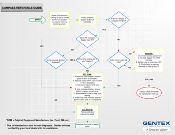
TOOLS NEEDEDIn addition to your regular tools, you will need, at least, the following:Crimping toolWire stripperContinuity testerElectric drill1 5/8" Hole sawNOTE: USE A QUALITY TOOL TO AVOID OVER-CRIMPING.CAUTION: DO NOT USE A TEST LIGHT TO TEST THE COMPUTER ORSENSOR WIRING OR YOU WILL DAMAGE THE COMPUTER.NOTE: for the rubber grommet in the firewall.KIT CONTENTSTake inventory to see that you have everything you are supposed to have in this kit, ifanything is missing, contact the dealer where you obtained the kit or contact PainlessPerformance at (800) 423-9696 or (817) 244-6898.The kit should contain the following items: The main wire harness Fuel Injection Installation Instructions P/N 90570 (This Booklet) 4” & 7” tie wraps, fuse block mounting bracket & screws, brake switch, splices andterminals TAC Module to Accelerator Pedal Pigtail, Gas Injector Harness, Flex Fuel InjectorHarness, ’05-’06 Knock Sensor PigtailFigure 1 Content of the 602216
PRE-INSTALLATION AND HARNESS ROUTINGGUIDELINESFamiliarize yourself with the harness by locating each of the harness groups and bylooking at the connectors on the wire ends. A good exercise is to lay out the wire harness on thefloor and identify all the connectors, sections, and wires.Disconnect the battery if it has not already been disconnected. The sensors andcontrol systems used by electronic fuel injected vehicles are very sensitive. Any shorts can andwill cause severe damage to these components.The installation of your harness kit will consist of two parts: The physical routing, positioning, securing, group/ individual wires and connectors.The proper electrical connection of the individual circuits.We cannot tell you how to route the harness in your vehicle. That depends a great dealupon the particular make of the automobile and what extent you want to secure and conceal theharness. To help you begin thinking through the installation of your wire harness we can onlyreally offer some general guidelines and routing practices, general installation instructions in, allof which can be found below. You will want to route the harness through and around open areas. Inside edges provideextra protection from hazards and also provide places for tie wraps, clips, and othersupport. Route the harness away from sharp edges, exhaust pipes, and the hood, trunk, and doorhinges. Plan where harness supports will be located. Use a support or zip tie approximately every6 inches. Allow enough slack in the harness at places where movement could possibly occur (bodyto frame, frame to engine, etc.)HARNESS ATTACHMENTNOTE: Harness routing and shaping will be a time-consuming task. Taking your time willenhance the beauty of your vehicle. Please take your time and be patient.Mold harness groups to the contour of the dash, engine, frame, etc. Remember to routethe harness away from sharp edges, exhaust pipes, hinges, and moving parts.Attach harness groups to your vehicle with clips or ties starting at the computer andworking your way outward.Note: Do not tighten tie wraps or mounting devices until the entire harness is installed.Make all harness attachments LOOSELY.Connecting the wires and connectors throughout the harness is a simple process. Makesure that each wire is properly routed and then attached.When all the wires are attached, tighten the mounts and ties to secure the harnesspermanently.When used every 1-1/2" or so on the visible areas of the harness, plastic wire ties makea very attractive assembly. Otherwise, a tie installed in other areas every 6" or so will hold thewires in place securely.REMEMBER TO TAKE YOUR TIME.7
GROUNDING THE VEHICLEA perfectly and beautifully wired automobile will nevertheless have problems if everythingis not properly grounded. Don't go to the effort to installing a quality wire harness only to neglectproper grounding.NOTE: The installer of this harness is responsible for all ground wires not provided withthis part. These grounds are as followed: Connect a ground strap or cable (minimum of a 4 Ga. wire) from the negative batteryterminal to the chassis (frame). Connect a ground strap (minimum of a 4 Ga. wire) from the engine to the chassis (frame).Do not rely upon the motor mounts to make this connection. Connect a ground strap from the engine to the body.INSTALLATION INSTRUCTIONSFuse Block, ECM, TAC Module, Pedal Mounting and ConnectionsBelow you will find part numbers for parts compatible with this wire harness.Main ComputerTAC ModuleAccelerator PedalGM #89017733, 12576106, 12583560, or 12602802GM#12588923Delco#15264643 Decide where and how the ECM, TAC Module, and fuse block will be mounted. In mostcases these components can be mounted either under the dash or in the kick panel area.All parts are weatherproof and can be mounted in the engine compartment if necessary. Take notice of how much distance the harness will allow for ECM and Fuse Blockmounting. A bracket and mounting screws have been included for fuse block mounting.ECM mounting must be handled by the installer. The TAC Module and Pedal can both be mounted using the mounting holes found onthese components. The TAC Module must be mounted within 96” of the accelerator pedal,due to the length of the pigtail contained in the kit, and within 15” of The ECM due to thelength given in the harness. Once these locations have been determined, and double checked for accuracy, mount theECM, Fuse Block, TAC Module, and Accelerator Pedal. Drill a 15 8" hole for the firewall grommet near the ECM for the engine group and tail sectionto pass through. If the ECM and fuse block are mounted in the engine compartment, asmaller hole and grommet for the “Dash” portion will be required instead of the 15 8” hole.The “Dash” portion of the harness will not be labeled as such, information on identifyingthis portion can be found on the next page. Route the engine group, cooling fan wires, fuel compensation connector (if used, see p.15), and tail section through the hole. Push the grommet (already installed on the harness)into the hole until it is seated. Again, if the ECM and fuse block are mounted in the enginecompartment, the “dash” section of the harness will pass through this hole. Route the dash group over to the driver's side of the vehicle if it is not already there. Attach both ECM connectors to the computer. When connecting the plugs to thecomputer USE EXTREME CARE to make sure none of the pins in the computer areor become bent.8
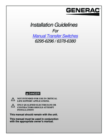
Locate the “Accelerator pedal to TAC Module” pigtail. Connect the pedal connector to theaccelerator pedal. See Figure 2 Attach the TAC module connection from the “Accelerator pedal to TAC Module” pigtail tothe TAC module. Attach the TAC Module connection from the main harness to the TACmodule. See Figure 3FIGURE 2 Accelerator PedalFIGURE 3 TAC Module ConnectionsDASH PORTION; INFORMATION & INSTALLATIONThe wires in this group consist of the Diagnostic Link Connector or DLC and check enginelight (pre-mounted into a mounting bracket), Cruise Control (4 wires), Ignition Voltage source (1wire), Fuel Test (1 wire), VSS Output (1 wire), A/C Request (1 wire), Brake Switch (3 wires), andTach (1 wire).All of these connections, with the exception of the DLC, are open ended wires. Thesewires will require you, the installer, to crimp on a terminal from the parts kit in order to make thecorrect connections needed. Follow the instructions given for proper terminal installation.Terminal Installation Information Have all tools and connectors handy. Select the correct terminal for the wire and application. Determine the correct wire length and cut the wire. Remember to allow enough slack inthe harness and wires at places where movement could occur. DOUBLE CHECK YOURCALCULATIONS. Strip insulation away from wire. Only strip as much insulation off as necessary for the typeof terminal lug you are using.Note: In the following step, make sure that the terminal is crimped with the proper die inthe crimping tool. An improper crimp will not make a good connection. DO NOTOVER-CRIMP. Crimp the terminal onto the wire and connect.DLC - The Data Link Connector (DLC) is used to communicate with the ECM. The Powertrain,On Board Diagnostic (OBD) System Check is an organized approach to identifying aproblem created by an electronic powertrain control system malfunction. The PowertrainOBD System Check is the starting point for any drivability concern diagnosis. ThePowertrain OBD System Check directs the installer to the next logical step in diagnosinga drivability concern. Understanding and using the Powertrain OBD System Checkcorrectly will reduce the diagnostic time and prevent the replacement of good parts.9
Mount the DLC connector usingthe bracket that the light ismounted in. Mount it in a positionthat allows access to the front ofthe connector and also allows youto see the light while driving. The light should illuminate whenthe ignition is in the “On/Run’position and during engineranking. If the light is on, while theengine is running, the ECM hasthrown a code which may or maynot affect drivability. See Figure 4Figure 4 Data Link ConnectorCruise Control- There are four cruisecontrol wires in this harness. Mostlate model GM steering columnsyears 1983-1993 already have orcan be retrofitted with a cruisecontrol switch. See Figure 5 forthe proper connection of thesewires to a factory GM cruisecontrol switch part number25111262. This harness kit doesnot include the connector neededbecause it has been discontinuedby Delphi.FIGURE 5 Cruise Control The BROWN wire(connector pin A). The GRAY wire is the cruise control on switch signal (connector pin B). The BLUE wire is the cruise control set/coast switch signal (connector pin D). The GRY/BLK wire is the cruise control resume/accel switch signal (connector pin C).ispowerFUSE BLOCK IGNITION - This circuit is used to provide power to the injection system. Connect this single Pink wire to a terminal/ wire from the ignition switch that is hot in theRUN and CRANK positions. Failure to provide power in the crank position will result inPCM shutdown while the engine is trying to start. This wire is simply activating an IgnitionRelay in the fuse Block. The coil wire from your chassis harness (#920 Coil B found onPainless Chassis harnesses) will be a perfect power source for this IGN wire. Note: Youwill know this circuit is properly connected if the Check Engine Light is on when theignition switch is on and while starting.FUEL TEST (use as needed) – This will be a single gray wire. This circuit is used to power theelectric fuel pump for test purposes only. Temporarily apply fused positive power to thiswire for testing the fuel pump. This wire is used to bypass the fuel pump relay found onthe fuse block for fuel pump testing and priming.TACH (optional) - This will be a single white wire. This circuit is used to provide a signal from theECM to the tachometer. Connect this wire to the signal input on the tachometer. Somemay notice an inaccurate RPM reading; consult the tech dept of the tachometermanufacture for compatibility.10
VSS OUTPUT (optional) - This will be a single green/white wire, do not get it confused with thegreen/white A/C Request wire. This circuit is used to provide a signal from the PCM to theelectric speedometer. Connect this wire to the signal input on the electric speedometer(not all aftermarket electric speedometers use the same signal for operation. Consult thetech dept of the speedometer manufacture for compatibility).BRAKE SWITCH – This will be a group of three wires. These circuits are used to provide powerto the TCC solenoid in the automatic transmission. These wires will connect to the brakeswitch terminals that are normally used for cruise control or TCC solenoid (normallyclosed). These wires do not connect to the terminals for the brake lights, only thelight blue wire will connect to this terminal. If you are using the included brake switch then you will need to install it and wire itaccording to Figure 6. The pink wire to the back of the switch in the illustration is the wirethat has power on it whether or not the brake is being applied. If your vehicle has a pressure type brake switch, you may use a relay as shown in Figure7. The relay must be a SPDT Relay and wired correctly or it could result in a dangeroussituation with the vehicle. The torque converter may not unlock.FIGURE 6 Brake Switch ConnectionsFIGURE 7 Brake Switch Relay11
AC REQUEST – This is not a power supply for the compressor. This circuit is used to informthe ECM that the AC compressor has been turned on. This will be a single green/white wire; do not get it confused with the green/white VSSOutput wire. This wire is to be spliced into the circuit from the AC switch to the AC compressor.ENGINE CONNECTIONSPainless recommends the use of the listed or equivalent part numbers. These will meetall requirements and are compatible with the Painless harness. The numbers given are GM andAC Delco part numbers for the sensors and components found on the ’03 – ’06 engines.MAF/ IAT SensorEngine Coolant TemperatureThrottle BodyMAP SensorKnock SensorCoilsCam Position SensorCrankshaft Position SensorDelco# 213-364Delco# 213-953GM# 12570800Delco# 213-796Delco# 213-362GM# 10457730GM# 12561211Delco# 213-354The engine group is designed to be separated into left (driver) and right (passenger)sections. Each side is tie-wrapped separately, BUT NOT LABELED. The left side of the enginehas the connectors for the alternator, driver side coils, mass air flow sensor, and engine coolantsensor, all of which ARE labeled. When you begin routing, FIRST separate the engine group intoleft and right sections, and place them accordingly.NOTE: Before you connect any wires, separate the tail section from the engine group and placeit out of the way.KNOCK – To control spark knock, aKnock Sensor system is used.This system is designed to retardspark timing up to 20 degrees toreduce spark knock in the engine.This allows the engine to usemaximum spark advance toimprove drivability and fueleconomy. This connection is a 2-pin blackconnector with a Blue and a lightblue wire. ’03 & ’04 motors have the knocksensors located under the intakemanifold in the lifter valley. Thisconnection can be found comingfrom a factory pigtail at the back ofthe intake manifold; as seen in thephoto to the left. FIGURE 8 ’03 & ’04 Knock Sensor connection’05 & ’06 motors have the knock sensors located on each side of the engine block. Theknock sensor pigtail included with the Painless harness will need to be plugged into theKnock Sensor connector of the 60221 harness. The dark blue wire of the pigtail willconnect to the driver side knock sensor. The light blue wire will connect to the passengerside knock sensor.12
CKP – The Crankshaft Position (CKP) sensorprovides the ECM with crankshaft speedand crankshaft position. The ECM utilizesthis information in order to determine if anengine misfire is present. The ECMmonitors the CKP sensor for momentarydrop in crankshaft speed in order todetermine if a misfire is occurring. /WHITE, YELLOW/BLACK, andLIGHT GREEN wires. The Crank Position Sensor can be foundjust above the starter. The starter willneed to be removed in order to make thisconnection. This connection can be seenin the photo to the right.FIGURE 9 Crankshaft Position SensorSTARTER B - These circuits are used to maintain memory in the ECM and provide power to thefuse block and to all heavy amp circuits. These wires consist of 2 large gauge red wires with ring terminals pre-installed. Connect these wires to the battery post on the starter solenoid (the same post as thepositive battery cable) or to a positive high output battery source.TO STARTER SOL (optional) – This circuit is used to connect the neutral safety switch to thestarter solenoid “S” terminal. This is only applicable for those using a 4l60E, 4L65E,4L80E, or 4L85E transmission. This will be a single yellow wire found with the Starter B wires. Connect this wire to the starter solenoid “S” terminal.GROUND –These circuits are used to provide ground for the entire Painless harness. This groupof wires MUST be connected for this harness and your fuel injection system to workproperly. This group of wires contains three black/white and two black wires, all pre-installed into 3ring terminals; some wires double up with other wires into one ring terminal. Connect these wires under different bolts in the back of the cylinder heads; there areexisting holes which can be used for this (will require M10x1.5 bolts). Do not stack thesegrounds under one bolt, they must be attached to 3 different grounding points for properoperation. For best results from your EFI system, be certain your grounding surfaces areclean and your connections are secure.CMP- The Camshaft Position (CMP) sensor provides the ECM with camshaft speed andposition. The ECM monitors the CMP sensor for any momentary drops in camshaft speedin order to determine if a misfire is occurring. This connection is a 3-pin black connector with brown/white, pink, and red wires. This Camshaft Position Sensor can be found at the back of the engine, behind the intakemanifold, as seen in Figure 10.13
Figure 11 MAP SensorFigure 10 Camshaft Position SensorMAP – The Manifold Absolute Pressure (MAP) sensor responds to changes in the intake manifoldpressure as a result of engine load and speed. The map sensor converts this to a voltageoutput seen by the ECM. This connection will be a gray 3 pin connector with gray, light green, and orange/blackwires. The MAP sensor can be found under the engine cover, on top of the intake manifold, atthe rear of the engine, as seen in Figure 11.DRVR. & PASS COILS-. The ignition system on this engine is a multiple coil configuration called“coil on plug”. The ignition coil mounting bracket is attached to the rocker cover. Thesecondary ignition, or spark plug, wires are short compared to a distributor ignition systemwire. Both of these connections, located on opposite side of the engine breakout, are 7-pin,white connectors. The 2-coil connectors found on the Painless harness plug into the large white connectorsfound on the factory coil harnesses. This factory harness can be found on the coil mounting bracket located on the valve cover,see Figures 12 & 13 below.Figure 13 Passenger Side Coil ConnectionFigure 12 Driver Side Coil Connection14
ECT – The ECM supplies a 5.0-volt signal to theEngine Coolant Temperature (ECT)sensor through a resistor in the ECM andmeasures the voltage. The voltage ishigh when the engine is cold. The voltageis low when the engine is hot. The ECMcalculatestheenginecoolanttemperature by measuring the voltage.The engine coolant temperature affectsmost systems the ECM controls.Figure 14 ECT Sensor This connection will be a 2-pin blackconnector with yellow and gray wires. This sensor can be found on the side ofthe head, front driver side, behind thealternator. It can also be seen to the leftin Figure 14.ALT- This circuit is used to excite (turn on) thevoltage regulator. When using the stockalternator equipped on the 4.8, 5.3 or 6.0LVortec engines, this connector willconnect into the voltage regulator plug. This connection will be a 4-pin connector,but will only have 2 wires going to thecenter pins. These will be a brown wireand a gray wire. The alternator will mount on the upperdriver side serpentine bracket.Figure 15 AlternatorMAF-IAT – The Mass Air Flow (MAF)sensor measures the amount andtemperature of the air whichpasses through the sensor. TheECM uses this information todetermine the operating conditionof the engine in order to controlthe fuel delivery. A large quantityof air indicates acceleration. Asmall quantity of air indicatesdeceleration or idle.Figure 16 Mass Air Flow / Air Intake Temp. Sensor15 This connection will be a black 5pin connector with black, tan,black/white, yellow, and pinkwires. The mass air flow will mount inline of the air intake to the throttlebody with the screen end furthestfrom the throttle body.
THROTTLE BODY- The throttle body receives signal from the TAC Module according to the acceleratorpedal position the TAC Module sees. Located inside the throttle body, a throttle position sensorsenses the throttle blade angle and relays that information to the ECM. The ECM requiresknowledge of throttle angle in order to generate the required injector control signals, or pulses. This connection will be a black 8 pin connector with yellow, black, brown, black/white, gray, green,purple, and light blue/black wires. The connection can be found on the passenger side of the throttle body.INJ #1 - #8 – The fuel injector assembly is a solenoid operated device controlled by the ECM that meterspressurized fuel to a single engine cylinder. An injector that has been sitting for more than 6months will need to be cleaned/ replaced as the varnish residue in the fuel will cause the injectorto stick closed. This will keep the injector from delivering fuel as needed by the injection system.These engines came from the factory with regular gas systems/injectors as well as flex fuel (E85)systems. The injectors found on the flex fuel systems differ from those found on the gas systems. Injectorsub harnesses have been included with your Painless kit to work with both injector types. If using the flexfuel injectors, a fuel compensation sensor (p. 15), must be used. Locate the sub harness that matches your injector connection type. Plug this sub harness into the connector found on the Painless harness labeled “Fuel Injectors”,this connector can be found at the break out of the engine portion of the harness. Route and connect Injectors #1, #3, #5, and #7 down the driver side of the engine. Route and connect Injectors #2, #4, #6, and #8 down the passenger side of the engine.FIGURE 18 Injectors 2, 4, 6, 8FIGURE 17 Injectors 1, 3, 5, 7COOLING FAN(s)- 2005 and 2006 engines came from the factory with electric cooling fans.These fans are ground activated by the ECM according to engine temperatures read bythe engine coolant temperature sensor. In order for the ECM to operate this circuit, yourECM must be flashed as a 2005 or 2006 vehicle. The on/off activation temperatures canbe changed in the ECM programming to your liking. 2 wires have been provided for cooling fan operation, a white wire (low) and a blue wire(high). The blue wire is only needed if you have a dual fan setup and will cycle the separatefan individually. The white wire can be used to power a cooling fan. This wire comes from the 30-ampcooling fan relay found in the fuse block. This wire will only have power when the enginehas come up to temperature and the ECM activates the relay. The blue wire is simply an activation wire for a separate fan relay. This wire will not powera cooling fan; it is a ground wire from the ECM which will only activate a fan relay. Thiswire will need to connect to the 86 or 85 terminal of a fan relay which is wired to be groundactivated. Painless ECM Controlled Fan Relay kits (#30109 or #30133) are perfect for this.16
TAIL/TRANSMISSION GROUP INSTALLATIONO2 SensorsRange, Park/Neutral SwitchGM# 12573005, 12587785, or equivalentGM# 29540479Locate the tail section that you earlier separated from the engine group. Begin routing ittowards the rear of the vehicle. Be sure to avoid all sharp edges, moving or hot parts, or anythingelse that may damage the harness.LEFT & RIGHT O2 SENSORS – The ECM uses the signal voltage from heated oxygen sensorsin a Closed Loop to adjust the fuel injector pulse width. In Closed Loop, the ECM adjustsfuel delivery to maintain an air to fuel ratio which allows the best combination of emissioncon
feel free to call Painless Performance Products' Tech Line at 1-800-423-9696. The Tech Line can be reached from 8 A.M. to 5 P.M. central time, Monday through Thursday, and 8 A.M. to 4:30 P.M. on Fridays. We have attempted to provide you with as accurate of instructions as possible and ar