Transcription
Installation GuidelinesForManual Transfer Switches6295-6296 / 6378-6380*NOT INTENDED FOR USE IN CRITICALLIFE SUPPORT APPLICATIONS.*ONLY QUALIFIED ELECTRICIANS ORCONTRACTORS SHOULD ATTEMPTINSTALLATION!This manual should remain with the unit.This manual must be used in conjunctionwith the appropriate owner’s manual.
ForwardThank you for purchasing a Generac Manual Transfer Switch to safely connect a portable generator to your home or business (single phase). Use where the main electrical panel is located indoors. This product is suitable for service entranceequipment.READ THIS MANUAL THOROUGHLY. This manual has been prepared to familiarize personnel involved with theinstallation of transfer switches with the manufacturer’s installation requirements. Information and instructions contained herein are not intended to replace or supersede, local, state, or national safety, electrical, and building codespertaining to such installations. Applicable laws, codes, and standards must always take precedence over the recommendations contained herein. Always check with the local Authority Having Jurisdiction (AHJ) for the codes or standards that apply.Only authorized dealers or qualified, competent installation contractors or electricians thoroughly familiar with applicable codes, standards, and regulations should install this transfer switch. The installation must be in strict compliancewith all codes, standards, and regulations.It is not intended that this manual be used by any unqualified person for the purpose of installing a transfer switch.Installation, inspection, and testing of the system must be attempted only by competent, qualified electricians or installation contractors who are familiar with the equipment and with all installation codes and requirements.It would be impossible to provide details for every installation configuration. For this reason, much of the information inthis manual is general in nature. Illustrations of typical installations are not intended to serve as specific installationplans, but may be used in the planning and design process when considering the selection and purchase of a generator set for standby power applications. Always have the unit specific drawings and manuals on hand before beginningany installation. If a portable generator is used to power electrical load circuits normally powered by a utilitypower source, it is required by code to install a transfer switch. The transfer switch musteffectively isolate the electrical system from the utility distribution system when the generatoris operating. Failure to isolate an electrical system by such means may result in damage to thegenerator and may also result in injury or even death to utility power workers due to backfeedof electrical energy. After the transfer switch has been installed, do nothing that might render the installation in noncompliance with codes, standards, and regulations. Every effort was made to ensure that theinformation in this manual was both accurate and complete at the time it was released. However,the manufacturer reserves the right to change, alter, or otherwise improve this product at anytime without notice.WARNING!California Proposition 65Engine exhaust and some of its constituents are known to the state of California to cause cancer,birth defects, and other reproductive harm.WARNING!California Proposition 65This product contains or emits chemicals known to the state of California to cause cancer,birth defects, and other reproductive harm.iiTransfer Switch Installation Guidelines
Table of ContentsTable of ContentsForward .iiSection 1 Safety1.1 Introduction . 11.2 Safety Rules . 11.3 General Hazards . 21.4 Electrical Hazards . 21.5 Fire Hazards . 31.6 Explosion Hazards . 31.7 Standards Index . 3Section 2 Installation2.1 What is Included in this Carton: . 42.2 Tools and Items Needed for Installation: . 42.3 Optional Items for Installation: . 42.4 Specifications . 52.5 Planning Your Installation . 52.6 Installation Procedure . 6Section 3 Operation3.1 Using Your Transfer Switch . 9Transfer Switch Installation Guidelinesiii
Section 1Safety1.1 — IntroductionThank you for purchasing a Generac Manual Transfer Switch to safely connect a portable generator to your home or business (single phase only). Use where the main electrical panel is located indoors. This product is suitable for service entranceequipment.Read this manual thoroughly. If any portion is not understood, contact the nearest Authorized Generac ServiceDealer for clarification. Only authorized dealers or qualified, competent installation contractors or electricians thoroughly familiar with applicable codes, standards, and regulations should install this transfer switch.These individualsare trained/qualified service technicians familiar with the control systems and available options, and also have fullaccess to drawings, publications, and other information required for a successful installation.The installation must be instrict compliance with all codes, standards, and regulations.1.2 — Safety RulesThroughout this publication, DANGER, WARNING, CAUTION, and NOTE boxes are used to alert personnel to specialinstructions about a particular operation that may be hazardous if performed incorrectly or carelessly. Observe themcarefully. They indicate:Indicates a hazardous situation or action that, if not avoided, will result in death or seriousinjury.Indicates a hazardous situation or action that, if not avoided, could result in death or serious injury.Indicates a hazardous situation or action that, if not avoided, could result in minor or moderate injury.NOTE: Notes provide additional information important to a procedure or component.These safety warnings cannot eliminate the hazards they indicate. Observing safety precautions and strict compliancewith the special instructions while performing the action or service are essential to preventing accidents.Four commonly used safety symbols accompany DANGER, WARNING, and CAUTION boxes and the type of information each indicates:Transfer Switch Installation Guidelines1
Safety ! This symbol points out important safety information that, if not followed, couldendanger personnel and/or property.This symbol represents the potential for an Explosion Hazard.This symbol represents the potential for a Fire Hazard.This symbol represents the potential for an Electrical Shock Hazard.SAVE THESE INSTRUCTIONS. This manual contains important instructions that should befollowed during installation of the transfer switch. The manufacturer suggests that thesesafety rules be copied and posted in potential hazard areas. Safety should be stressedto all installers, operators, potential operators, and service and repair technicians forthis equipment.The manufacturer cannot anticipate every possible circumstance that might involve a hazard. The warnings inthis manual, and on tags and decals affixed to the unit, are not all-inclusive. If using a procedure, work method, or operating technique the manufacturer does not specifically recommend, ensure that it is safe for others. Also make sure theprocedure, work method, or operating technique used does not result in unsafe conditions.1.3 — General Hazards For safety reasons, the manufacturer recommends that this equipment be installed, serviced, and repaired by anAuthorized Service Dealer or other competent, qualified electrician or installation technician who is familiar withall applicable codes, standards, and regulations. Ensure that the transfer switch is installed, operated, and serviced in accordance with the manufacturer’s instructions and recommendations. Following installation, do nothing that might render the unit unsafe or in noncompliance. Keep the area around the transfer switch clean and uncluttered. Remove any materials that could become hazardous. When working on this equipment, remain alert at all times. Never work on the equipment when physically or mentally fatigued. Inspect the portable generator regularly, and promptly repair or replace any worn or damaged components usingonly factory approved parts and procedures.1.4 — Electrical Hazards All generators produce dangerous electrical voltages and can cause fatal electrical shock. Utility power deliversextremely high and dangerous voltages to the transfer switch as well as the generator when it is in operation.Avoid contact with bare wires, terminals and other connections. Ensure all covers, guards, and barriers are inplace, and that they are properly secured and/or locked before operation. If work must be done around an operating unit, stand on an insulated, dry surface to reduce potential shock hazard. Do not handle any kind of electrical device while standing in water, while barefoot, or while hands or feet are wet.DANGEROUS ELECTRICAL SHOCK MAY RESULT. If it is necessary to stand on metal or concrete while installing, operating, servicing, or repairing this equipment,lay down a dry wooden platform and cover with insulated mats before beginning. Verify that the portable generator is properly grounded. Wire gauge sizes of electrical wiring, cables, and cord sets must be adequate to handle the maximum electricalcurrent (ampacity) to which it will be subjected. Before installing or servicing equipment, verify that all power voltage supplies are positively turned off at theirsources. Failure to do so can result in hazardous and possibly fatal electrical shock.2Transfer Switch Installation Guidelines
Safety Connecting a portable generator to an electrical system normally supplied by an electric utility is by means of thetransfer switch so as to isolate the generator’s electric system from the electric utility distribution system whenthe portable generator is operating. Failure to isolate the two electric system power sources from each other bysuch means will result in damage to the portable generator and may also result in injury or death to utility powerworkers due to backfeed of electrical energy. In case of accident caused by electric shock, immediately shut down the source of electrical power. If this is notpossible, attempt to free the victim from the live conductor. AVOID DIRECT CONTACT WITH THE VICTIM. Usea nonconducting implement, such as a dry rope or board, to free the victim from the live conductor. If the victim isunconscious, apply first aid and get immediate medical help. Do not wear jewelry when working on this equipment. Jewelry can conduct electricity resulting in electric shock,or may get caught in moving parts resulting in injury.1.5 — Fire Hazards Keep a fire extinguisher near the portable generator and transfer switch at all times. Keep the extinguisher properly charged and be familiar with its use. Direct any questions to the local fire department.NOTE: DO NOT use any carbon tetra-chloride type fire extinguishers. These fire extinguishers emit toxic fumesand the liquid can damage wiring insulation.1.6 — Explosion Hazards Do not smoke around the generator. Immediately wipe up any fuel or oil spills. Ensure that no combustible materials are left in the generator compartment, or on or near the generator, as FIRE or EXPLOSION may result.Keep the area surrounding the generator clean and free of debris. All types of fuels are potentially FLAMMABLE and/or EXPLOSIVE and must be handled with care. Inspect thefuel system frequently and correct any leaks immediately. Be sure fuel supply lines are properly installed, purged,and leak tested before placing the generator set into service.1.7 — Standards IndexBe sure the transfer switch is in strict compliance with all applicable local, state, and federal laws, codes, and regulations pertaining to such installations. Always use the current version or edition of the applicable law, code, and regulation as it applies to the local jurisdiction.Transfer Switch Installation Guidelines3
InstallationSection 2Installation2.1 — What is Included in this Carton: Manual Transfer Switch with wire harness, conduit, fittings and wire connectors (10 or 12) Wire Harness, pre-assembled 30 amp or 50 amp Aluminum Power Inlet Box (Models 6295-6296 only) 10 Foot Power Cord (Models 6295-6296 only) Flanged Inlet (inside models 6378 and 6380 only) Installation Manual and Warranty Registration card2.2 — Tools and Items Needed for Installation: 5/16” nut driver, 2-1/8” hole saw (if flush mounting) Screwdrivers, straight blade and Phillips Electric drill, drill bits, wallboard saw Wire cutter/stripper Safety eye goggles Anchors and screws to mount transfer switch to wall/wallboard New, 2-pole 60 Amp or 100 Amp, 240V circuit breaker to install in main load center – same manufacturer as existing load center Insulated building wire (4-wire, also known as 3-wire plus ground) and conduit to connect between power inlet box and transfer switchCompatible Circuit Breakers:Siemens/Murray QT, QPH, HQP, QPF (GFCI), QPHF, QFP, QE, QEH, QAF (Arc Fault), QP (Surge Protector)Cutler-Hammer Series BD, BR, BQ, GFCChallenger Type A, C, HAGFSquare D Series HOM (Homeline)GE Series THQL2.3 — Optional Items for Installation: Arc-fault, GFCI or Surge protection circuit breakers. If Arc-fault, GFCI or Surge protection circuit breakers are used as the branch circuit protector in the main load center, they MUST be used in the manual transfer switch. You may be able to re-use your existing AFCI, GFCI andSurge protection circuit breakers in the manual transfer switch. See list of compatible breakers. Wire, fittings and conduit to connect the Power Inlet Box to the transfer switch. White, green, black and red THHN or MTW wire, 10 AWG, 300V rated (if breaker configuration is modified or expanded. Switched Neutral Kit (Model 6297). If your portable generator has the neutral bonded to the frame of the generator AND 240V “full-power”receptacle is GFCI protected, you will need to install this accessory with your transfer switch to avoid nuisance tripping of the GFCI breakeron the generator.NOTE: ON NEUTRAL BONDED GENERATORS: Some portable generators are intended for use on jobsites, and therefore are subject toOSHA regulations for GFCI protection on all receptacles. These "contractor grade" generators have their neutral wire bonded to theground wire to pass OSHA inspection on job sites, and when connected to a transfer switch, this may cause nuisance tripping of thegenerator GFCI breaker. If you’re using a neutral bonded generator to power a house or building through a transfer switch, then determine if the neutral bond wire on the generator can be disabled without voiding the warranty, preferably by a dealer or a qualified electrician. NOTE: After this action, the generator will no longer pass OSHA inspection on job sites. Consult the manufacturer of yourgenerator to determine if the neutral bond can be removed. If it can be disabled, then no modifications to your transfer switch installation are needed. If the neutral bond cannot be disabled or voids the generator warranty, you must install a Switched Neutral Kit (SNK)accessory with your transfer switch.4Transfer Switch Installation Guidelines
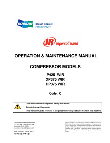
Installation2.4 — SpecificationsModel6295 or 63786296 or 63801012# Circuits Provided on Transfer SwitchMaximum # Circuits1616REQUIRED BREAKER FOR MAIN LOAD CENTER(not included)60 amp 2-pole100 amp 2-poleUtility Main Breaker60 amp 2-pole100 amp 2-poleGenerator Main Breaker30 amp 2-pole60 amp 2-poleBreakers Provided with Unit3 – 15 amp 1-pole3 – 20 amp 1-pole1 – 20 amp 2-pole1 – 30 amp 2-pole3 – 15 amp 1-pole3 – 20 amp 1-pole1 – 20 amp 2-pole1 – 30 amp 2-pole1 – 50 amp 2-poleMaximum Generator Watts7500 continuous / 9000 surge12500 continuous / 18000 surgeMaximum Generator Amps30 Amps60 amps125/250 Volts125/250 VoltsNEMA Type Enclosure1 – Indoor Only1 – Indoor OnlyNEMA Configuration of Male Inlet in Power Inlet BoxNEMA L14-30CS-63651110/4 AWG6/4 AWGVoltagePhaseMinimum Gauge Cord SizeNOTE: If Ground Fault Circuit Interrupters (GFCI), Arc Fault Circuit Interrupters (AFCI), or Surge Protector Circuit Breakers were usedas the branch circuit protector in the main load center, they MUST be used in the transfer switch. GFCI and AFCI breakers require anisolated neutral connected from the load to the GFCI or AFCI. The load neutral needs to be connected with a wire nut to a 3-6 foot pieceof white wire, run through the harness conduit to the transfer switch and connected to the “load neutral” lug or pigtail on the GFCI orACFI breaker. Because GFCI and AFCI circuit breakers can take up more than one space, the overall maximum number of circuits maybe reduced from the number shown. Not all brands of GFCI and Arc Fault breakers will fit.2.5 — Planning Your Installation1. Determine the appliances, circuits or equipment you want to operate with generator power during a power outage, such as: Refrigerator/Freezer Water Heater Security System Furnace Blower (gas/oil only) Garage Door Opener Sump Pump TV / Radio Microwave, Coffee Maker Computer, Fax and Printer, Phone Lighting Well Pump Aquarium2. Determine the amps required for each appliance by reading the label on the appliance. IMPORTANT: No appliance should have an amperage rating that exceeds the GEN MAIN breaker rating in the transfer switch (SeeTable 1). The total amperage of all circuits can exceed the generator rating, but not all circuits will be able to beused concurrently.3. Assign the circuit # in the load center to a circuit (A2, B2, etc.) in the transfer switch matching the size of the circuit breaker in the load center to the circuit breaker in the transfer switch. Once you’ve determined which circuits you want to connect and the appropriate amperage, you will be ready to begin installing your transferswitch.4. The location of your load center/electrical panel in your home or business will determine where the transferswitch will be installed. Refer to Figure 1. In addition to the transfer switch, this kit includes a generator cordand power inlet box. You will use the generator cord to connect your generator to the power inlet box outdoors.Whether your load center is in a basement, interior room or garage, we recommend installing power inlet boxon the exterior of your house or building to avoid running generator cord through a door or window.5. Determine where you will install the power inlet box on an exterior wall at least 5 feet from any openings(doors, windows, vents, etc.). See Figure 1.Transfer Switch Installation Guidelines5
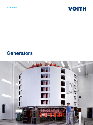
InstallationFigure 1: TYPICAL INSTALLATIONTable 1: CIRCUIT WORKSHEETCircuit6295 or 63786296 or ANAB720ANAAppliance(s) or Circuits2.6 — Installation Procedure 6PLEASE READ THIS MANUAL IN ITS ENTIRETY BEFORE ATTEMPTING TO UNPACK, ASSEMBLE, INSTALL,OPERATE OR MAINTAIN THIS EQUIPMENT. HAZARDOUS VOLTAGES ARE PRESENT INSIDE TRANSFER SWITCHENCLOSURES THAT CAN CAUSE DEATH OR SEVERE PERSONAL INJURY. FOLLOW PROPER INSTALLATION,OPERATION AND MAINTENANCE PROCEDURES TO AVOID HAZARDOUS VOLTAGES.Transfer Switch Installation Guidelines
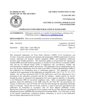
Installation TURN OFF THE MAIN CIRCUIT BREAKER IN THE LOAD CENTER BEFORE STARTING INSTALLATION.I. TRANSFER SWITCH INSTALLATION:A: Surface Mount Installation Using Power Inlet Box (included in models 6295-6296):1. Select a location on the left or right side of the Load Center to mount transfer switch, as it is provided with 24”of flexible conduit. Remove the cover to the load center and the cover of the transfer switch, save the screws.Measure and cut conduit to a length and snap provided fittings on ends. Locate and remove a knockout (KO)on lower side of load center that matches the conduit fitting size on the wiring harness. After attaching the flexible conduit to both enclosures through one of the bottom or side KOs, hold the transfer switch in positionagainst the wall on which it is to be mounted, mark the holes on the wall for the anchoring screws and anchorto wall (anchors not provided). Be sure NOT to stress the flexible conduit, as it may break. [NOTE: The Electrical Non-Metallic Tubing (ENT) provided is UL Listed and recognized by the National Electrical Code (NEC) forthis application. However, some local codes and inspectors may prohibit its use in buildings that exceed (3)floors above grade.]2. Fish the pre-assembled wire harness through the conduit. Strip each wire in the wire harness 5/8” and insertand tighten the wires to the correspondingly marked circuit breakers in the transfer switch. As you attach eachmarked wire to the circuit breaker, write the appliance name on the label on the transfer switch cover per theTABLE 2 CIRCUIT WORKSHEET completed in Step 1. The unmarked BLACK wires in the harness areinserted into the UTIL MAIN 2-pole breaker in the transfer switch. Attach the WHITE wire to the neutral barlocated on the right side and attach the GREEN wire to the ground bar located on the left side of the transferswitch.3. Install appropriately sized conduit, fittings and wire between the Power Inlet Box (Models 6295-6296 only)mounted on the building exterior and the transfer switch, referring to Power Inlet Box Install Instructions below.Locate and remove a KO on the right top or side of the transfer switch, pull wire into transfer switch enclosureand secure wire with fitting. Install the green ground wire into the ground bar on the left, and install the whiteneutral wire into neutral bar on the right. Using provided wiring connectors, connect black wire from PIB toblack wiring going to Meter “A”. Repeat for red wire from PIB to Meter “B”. Note: Models 6296 and 6380 usecurrent transformers (CTs) connected to the meters; pass the black wire from the PIB through the hole in theCT connected to the “A” meter before connecting to the “GEN MAIN A” circuit breaker. Repeat for the red wirefrom the PIB, passing through the hole in the CT connected to the “B” meter before connecting to the “GENMAIN B” circuit breaker. See FIGURE 2 WIRING DIAGRAM. Reinstall the cover to the transfer switch.4. In the main Load Center, remove the wires from the breakers for the loads that will be relocated to the transferswitch. Cut each harness wire to a convenient length, strip off 5/8” insulation and connect to the wires removedfrom the breakers per TABLE 2 with the provided wire connectors. Remove two adjacent single pole breakersfrom which the load wires were removed and install the NEW 60A or 100A 2-pole circuit breaker (as required inthe Other Items Needed section) in their place. Insert the unmarked BLACK wires from the harness into thenew circuit breaker. Terminate the WHITE and GREEN wire in the harness in an open position in the Neutraland Ground bars respectively. If there is no separate ground bar, insert the GREEN wire into an open positionin the NEUTRAL bar, and tighten.5. Reinstall the cover to the load center, and turn ON the MAIN breaker in the load center. Turn ON all branch circuit breakers in both panels. Turn ON the UTIL MAIN in the transfer switch. Check that power is restored to allappliances. Transfer switch installation is complete.B. Flush Mounting in New Construction (unfinished walls) Using Power Inlet Box (included in 6295-6296):1. Install the transfer switch at the same time as the main load center, in adjacent wall stud openings (the transferswitch enclosure is 14.25” wide and will fit in standard 16” wall framing). Remove the transfer switch dead frontcover, save the screws. Knock out the appropriate mounting slots on the sides of the enclosure and secure toframing with nails or screws; be sure the front edge of the enclosure extends forward to be flush with the thickness of the finished wallboard.2. Mark and drill a 2 1/8” diameter hole in the stud between the main load center and the transfer switch, lining upwith the lowest side KO in the load center and near the bottom center KO in the transfer switch. Remove theKO’s, cut the provided conduit to length, snap on the provided fittings to the conduit, push the conduit throughthe drilled hole and install the conduit assembly to the KO openings in the main load center and transfer switch.Transfer Switch Installation Guidelines7
Installation3. Complete Section A #3 above. Cut a piece of cardboard to 14.5” x 12.5”, using the 4 screws removed in Section A #1, attach the cardboard to the front of the transfer switch.4. After the walls have been finished and painted, remove the cardboard cover and complete the installation asdescribed in Sections A: #2, #4 and #5. NOTE: To simplify installation, all conductors for the branch circuits canbe terminated directly into the transfer switch instead of the main load center, eliminating the need to install theharness wires between the main load center and transfer switch for each circuit.C. Flush Mounting in Retrofit Construction (finished walls) Using Power Inlet Box (included in 6295-6296):1. Remove the dead front cover from the main load center and the transfer switch, save the screws.2. Determine where to install the transfer switch (keep in mind the length and flexibility of the conduit providedand where the generator wires will enter), Verify that there are no wires going through the side of the main loadcenter into the space where you want to mount the transfer switch. Use a “stud finder” to determine if you haveat least 14.25” between the studs to mount the transfer switch. Hold the transfer switch enclosure in thedesired position on the wall and mark the exact dimensions of the box. Set the enclosure aside and cut thehole in the wallboard.3. Remove a 1” or 1-¼” KO in the lower side (towards the hole cut in Step 2) of the load center. From the inside ofthe main load center, drill a ¼” pilot hole through the stud in the center of the KO removed. Reach down insidethe hole cut in Step 2 and drill a 2 1/8” diameter hole in the stud using the pilot hole as a guide. Remove thebottom center KO in the transfer switch, snap the fittings on the conduit, and attach the conduit assembly to thetransfer switch.4. Remove one of the KO’s on the top of the transfer switch enclosure and install an appropriately sized fitting forthe incoming wires from the Power Inlet Box. Knock out the appropriate mounting slots on the sides of thetransfer switch enclosure.5. Insert the transfer switch enclosure into the hole in the wallboard, inserting conduit fitting on attached conduitassembly into the KO removed in Step 3. Fasten conduit fitting to main load center with locknut. Secure transfer switch enclosure to framing with nails or screws; be sure the front edge of the enclosure extends forward tobe flush with the finished wallboard.6. Complete Sections A #2 through A #5 on page 5.II. EXPANDING OR RECONFIGURING YOUR TRANSFER SWITCH:This transfer switch ships from the factory with certain popular branch circuit breaker sizes. However, the circuitbreaker assortment can be modified to suit specific requirements, and this does not void the UL Listing. For example, ifthe 2-pole 20 amp circuit breaker is not needed, it may be removed from the panel and replaced with any combinationof the following: two separate full size breakers, four tandem (half size) breakers, one full size and two tandems, or aquad breaker. If additional circuit(s) are added, the installer is responsible for providing appropriately sized wire(s) foreach circuit.III. INSTALLING THE POWER INLET BOX (Models 6295 and 6296 Only):1. Remove the front cover of the power inlet box. Remove the 3 screws that secure the flanged inlet to the bottomplate.2. Mount the power inlet box on the outside of the building in a convenient location (minimum 24” above grade),using the four holes provided in the back of the enclosure. Use sealant around the anchoring screws to keepwater from entering the box at these mounting holes. Using approved wiring methods, install the wiring throughone of the knockouts provided in the enclosure. Be sure to seal around the hole in the building where the conduit enters through the wall.3. Extend wiring inside the power inlet box approx. 8” from the point of entrance. Attach green or bare groundwire to green lead provided in power inlet box with wire nut (provided by installer). Strip and insert incomingleads into terminals on flanged inlet. Insert white wire (neutral) into nickel-plated screw terminal or white marking on the flanged inlet.4. Carefully fold wires i
Manual Transfer Switch with wire harness, conduit, fittings and wire connectors (10 or 12) Wire Harness, pre-assembled 30 amp or 50 amp Aluminum Power Inlet Box (Models 6295-6296 only) 10 Foot Power Cord (Models 6295-6296 only) Flanged Inlet (inside models 6378 and 6380 only) Installation Manual and Warranty Registration .