Transcription
Modeling-challenge paradigm usingdesign of experiments (DOE)for spacecraft immersed in nonstationary,between-regimes, flowing plasmaMark Koepke1 and Richard Marchand21WestVirginia University, Morgantown, WV, USA2Universityof Alberta, Edmonton, Alberta, Canada
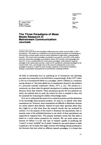
Methodologies foractive experiments in space and in the labSpace ObservationLab ExperimentAnalytical TheoryNumerical SimulationsDesign of Experiments (DOE) [think of a “wind tunnel”]
Design of Experiment (DOE) methodologyDefine standard experimental conditions and measurements to bemodeled numerically and computationally simulated. Calibratedsensor-level lab measurements (sensor units) provided as data set,without quantity-level, plasma-parameter-specific interpretations.For example, a Langmuir probe measurement would not be quotedin terms of electron density, electron temperature, or plasmapotential, but rather as a current-voltage trace. Similarly, resultsfrom ion or electron imagers would be represented as a particleflux or current, measured by a detector array, rather thanrepresented as a fluid temperature, density, and flow velocity.
Goal: “Whole-device modeling” ofSpacecraft-Environment Interactions“Computational fluid dynamics (CFD) validation cannot consist of thecomparison of the results of one code to those of one experiment. Rather, it isthe agglomeration of comparisons at multiple conditions, code-to-codecomparisons, an understanding of the wind tunnel corrections, etc., that leadsto the understanding of the CFD uncertainty and validation of its use as anengineering tool. Examples include comparisons of predictive CFD tosubsequently acquired test data. The question is not can CFD give a greatanswer for one or two test cases, but can the CFD “processes” give goodanswers for a range of cases when run by a competent engineer? This is whatvalidation for an intended purpose is all about.”E. N. Tinoco, Validation and minimizing CFD uncertainty for commercial aircraft applications,AIAA paper 2008-6902. Presented at the 26th AIAA Applied Aerodynamics Conference,August 18-21, Honolulu, Hawaii (2008)
Project Goals & Scientific Impact: Whole-device modelingDecipher, relate, quantify, and predict the mechanisms operating & processesoccurring in nature and address intermediate-regime, non-ideal conditionsand the associated challenges of additional physical phenomenathat create significant problems in computational science and engineering.Extend the ability to document and achieve accuracy in representing variables,conditions, processes, and dynamics well beyond the inference of a physicalparameter from an invasive sensor interpreted with the help of theory.Thus, an interpolated environment can be constructed volumetrically.In this case, the environment of a spacecraft immersed in aninhomogeneously perturbed plasma environment,can be reconstructed using instrument data processed to sensor unitsat original spatio-temporal resolution but without a requirement of havingtheory-interpreted derived values of each specific physical quantity!
Project Goals & Scientific Impact align with SHIELDSThe LANL SHIELDS Project: Space Hazards Induced near Earth by Large, Dynamic Storms: Understanding, Modeling, PredictingV. K. Jordanova, Space Science and Applications, LANL, at 2016 SHIELDS Workshop 4-8 April 2016Develop a new modeling capability of the complex near-Earth environment for spaceassets protection and Space Situational Awareness (SSA):Transformational: from correlative to causal understanding of a complex system,exciting new physics addressing interactions across multiple scales/plasma regimesApplication: mitigate spacecraft charging effects, assist spacecraft designers,forensic analysis of space system failures address intermediate-regime, non-ideal conditions and the associated challenges ofadditional physical phenomena that create significant problems in computational sci. & eng.Outstanding science questions related to storm/substorm dynamics we will answer:What determines where and when hot plasma is injected into the inner magnetosphere?How are the injected particles transported, and how does the magnetosphere respond?What waves do the injected particles excite andhow do these waves feed back on the acceleration and loss of the particles?Observations are inadequate to address these questions globally, modeling is the only way!
Advantage of DOE over conventional validationAction Plan: A conducting sphere and cylinder under the conditions ofnonstationary, between-regimes, flowing plasma is adopted as a test case fora modeling-challenge paradigm based on DOE methodology.Action Plan: Identify modeling challenges for more complex codes by includingthe kinetic nature of the plasma sheath and capturing non-monotonic profilesof density and E field from analytical predictions that are sufficiently non-idealto potentially distinguish one numerical simulation approach from another.Action Plan: Facilitate a RED-team/BLUE-team challenge that addressesspecific questions in Spacecraft-Environment Interactions and assesses thecapability of models to describe those non-straightforward conditions.Benefit: Streamlined model/simulation development.
Start small with proof-of-principle experimentKoepke/Marchand-Coordinated Modeling-Challenge Facilityon Spacecraft-Environment Interactionsusing laboratory facilities at West Virginia University and highperformance-computing facilities at University of Alberta and LANL.Even if 1st formal collaboration is between Koepke-Marchand, there could be aportal, with level-1B data downloadable by anyone interested, onto which anyparticipant could contribute simulation results. Such “users” have no financialobligation, but benefit scientifically/mutually with us (collaboration expansion).Grow, inclusively, as demand dictates into aCommunity-Coordinated Modeling-Challenge Facilityon Spacecraft-Environment Interactionsusing laboratory facilities nationwide and high-performance-computingfacilities at several institutions.
Solar Wind Facility, K. Wright, T. Schneider, J. Vaughn, P. WhittleseyApplied Space Environments Conference: Measurements,Models, Testing, and Tools, 15-19 May 2017, Huntsville, ALHistorically, NASA’s MSFC has operated a Solar Wind Facility (SWF) to provide long termparticle and photon exposure to material samples. The requirements on the particle beamdetails were not stringent as the cumulative fluence level is the test goal. Motivated bydevelopment of the faraday cup instrument on the NASA Solar Probe Plus (SPP) mission, theMSFC SWF has been upgraded to included high fidelity particle beams providing broadbeamions, broadbeam electrons, and narrow beam protons or ions, which cover a wide dynamicrange of solar wind velocity and flux conditions. The large vacuum chamber with integratedcryo-shroud, combined with a 3-axis positioning system, provides an excellent platform forsensor development and qualification. This short paper provides some details of the SWFcharged particle beams characteristics in the context of the Solar Probe Plus programrequirements. Data will be presented on the flux and energy ranges as well as beam stability.
Flowing Plasma Interaction with an Electric-Sail Tether Element, ToddSchneider, Jason Vaughn, Ken Wright, Allen Andersen, Nobie StoneApplied Space Environments Conference: Measurements,Models, Testing, and Tools, 15-19 May 2017, Huntsville, ALMotivated by interest in advancing the development of electric sails, a set of lab tests hasbeen conducted at MSFC to study the interaction of a drifting plasma with a sheath formedaround a small diameter tether element biased at positive voltages. The lab test setup wascreated with Debye length scaling in mind to offer a path to extrapolate (via modeling) to fullscale electric sail missions. Using a Differential Ion Flux Probe (DIFP), the interaction betweena positively biased tether element and a drifting plasma has been measured for severalscenarios. Clear evidence of the tether element sheath deflecting ions has been obtained.Maps of the flow angle downstream from the tether element have been made and they showthe influence of the plasma sheath. Finally, electron current collection measurements havebeen made for a wide range of plasma conditions and tether element bias voltages.
A fleet of CCMCF-ready facilities existsMSFCʼs Solar Wind FacilityMSFCʼs Heliopause Electrostatic Rapid TransitSystem (HERTS) FacilityVacuum chamber: 4 ft diameter x 8 ft long cylinder; LN2 cold shroud;quartz windows for solar photon input; base pressure at low 10-7 Torrwith oil-free pumpingIon source: Modified Kaufman-type with 10 cm diameter, collimating,matched grid set; housing electrically isolated from chamber; energyand flux computer controlledElectron source: biased filament accelerates electrons throughgrounded anode screen; energy and flux computer controlledPeabody Scientific ion source: water cooled Duo-plasmatron sourcewith steering and focusing in drift tube; pin-hole aperture can beinstalled in chamber for pencil beam; energy computer controlledTranslation and Rotation Stages: X- and Z- motion at 4000 steps/inch;rotation at 40 steps/degree; all motion computer controlledHelmholtz Horizontal Coils: Octagon shaped at 11’ by 11’ dimensionwith 9 turns of 12 gauge wire; computer controlled wire currentHelmholtz Vertical Coils: Square shaped at 6 ft by 6 ft dimension with8 turns of 12 gauge wire; computer controlled wire current
Two CCMCF devices are under assembly at WVUWVUʼs Blue TankWVUʼs Gold TankVacuum chamber: 0.5 m dia x 1.0 m long cylinder; basepressure at low 10-7 Torr with oil-free pumpingVacuum chamber: 2 m dia x 4 m long cylinder; basepressure at low 10-7 Torr with oil-free pumpingPlasma source: Hot-filament discharge, Mini-heliconplasma thrusterPlasma source: Large-diameter planar helicon antenna, hotcathode/mesh anode, washer gun, Q hot plateTranslation and Rotation Stages: X- and Z- motion; allmotion computer controlledTranslation and Rotation Stages: X- and Z- motion; allmotion computer controlledHelmholtz Horizontal-Field Coils: Circular, 1.2 m dia, 0.5 THelmholtz Horizontal-Field Coils: Circular, 1.8 m dia, 0.1 THelmholtz Vertical-Field Coils: Circular, 1.8 m dia, 0.1 T
Infrastructure for a Community-CoordinatedModeling-Challenge Facility (CCMCF)- Open to the entire stakeholder community. Allow any model to be tested againstmeasurements. A success metric is the realized testing-and-evaluation cycle time.- Ability to install and de-install test articles expeditiously to support high-frequency, shortduration tests focused in areas where primary uncertainties exist;- Ability to rapidly prototype and manufacture models that reflect the design changes that getinstantly transmitted by the customers of the test facility to their testing experimentalistsusing the latest in compatible CAD/CAM and model shop tools and materials;- Ability to efficiently modify test conditions or proceed through a test point matrix to minimizetime and effort spent while also maximizing respect of the DOE considerations;- Convenient and thorough diagnostic-tool accessibility;- Connectivity to high-performance computing capabilities to integrate and mergecomputational science and engineering simulations and test data;- Advances in data mining and data merging software as an integral part of the facility datasystems to enable rapid analyses of the variances along response surfaces; and- Virtual presence, networking, and connectivity to achieve a fully integrated Developmentaland Operational Test (DT/OT) approach in an inter-operable environment.
Bridging macro-and micro-scale models,combined with data assimilation toolsThe LANL SHIELDS Project: Space Hazards Induced near Earth by Large, Dynamic Storms: Understanding, Modeling, PredictingV. K. Jordanova, Space Science and Applications, LANL, at 2016 SHIELDS Workshop 4-8 April 2016Whereas the SWMF(Space Weather Modeling Framework)- captures rapid particle injection andacceleration during a substorm and- includes plasma wave generation andtheir feedback on the particles,CCMCF needs to- merge numerical simulation and testing tovalidate regional modeling- incorporate the complexity of real profiles- capture the coupling inherent in realprofiles, and- interpret holistically the deviations fromideal profiles.
CCMCF projects: Achieve a 2-way couplingbetween sensor data and simulationThe space environment affects spacecraft materials and equipment and aspacecraft and a rocket influences the space environment. The inclusion andjoint analysis of both aspects of spacecraft/environment interaction problempromotes the optimization and effectiveness of interpreting the experimentsto understand the operating mechanisms and relevant processes.1. Achieve a fully self-consistent “two-way” coupling between symmetric plasma conditions and probedetection. Demonstrate how a probe can measure its own surroundings by quantifying theperturbation inflicted onto the plasma and the probe signal by the presence of the probe itself.2. Achieve a fully self-consistent “two-way” coupling between asymmetric plasma conditions and probedetection. Quantify the perturbation inflicted onto a probe measurement by the presence ofinhomogeneous, nonstationary, between-regimes, flowing plasma.
CCMCF projects align with SHIELDS projectsThe LANL SHIELDS Project: Space Hazards Induced near Earth by Large, Dynamic Storms: Understanding, Modeling, PredictingV. K. Jordanova, Space Science and Applications, LANL, at 2016 SHIELDS Workshop 4-8 April 2016Spacecraft surface charging: interaction of a plasma with material objects, additionalscales due to the object: 'more' multiscale! Spacecraft charging is platform dependent LANL state-of-the-art Curvilinear PIC (3-D, parallelized, multigrid) will be used toperform simulations of spacecraft charging for the specific geometry & materialproperties of [Van Allen] Probes merge numerical simulation and testing to validate regional modeling that incorporates the complexity of real profiles, to capture the coupling inherent in real profiles,and to interpret holistically the deviations from ideal profiles.
CCMCF Infrastructure ‒ Facility teamMark Koepke (WVU, USA): Q machine, helimak, stellarator, theta- and z-pinch, andmirror-trap devices; hot and cold cathode, washer-gun, dc/rf/pulsed plasma sources;innovative probe, EEDF, IEDF, spectroscopic analysis, laser-induced fluorescence,interferometry, imaging, phase-resolved optical emission spectroscopy diagnosticsVladimir Demidov (WVU, USA): Langmuir probe theory, application, innovation;spectroscopic analysis of plasma; gas sensors, helimak devices, and dc discharges;turbulence-induced transport; atomic & molecular physicsEarl Scime (WVU, USA): Space instruments, spacecraft design, lab experiments(reversed-field pinch, helicon anntennae, double layers, plasma processing);microwave, probe, and laser-aided diagnostics of electrons, ions, and neutralsJulian Schulze (WVU, USA): Plasma-on-surface interaction, rf-plasma sources,partially ionized plasma diagnostics and simulationShunjiro Shinohara (TUAT, Japan): helicon sources, thrusters, & applications, spacesimulation chamber design, fabrication, operation, and diagnostic characterizationKevin Ronald (Univ. Strathclyde, UK): Electron beam injection, coherent beams andradiation, microwave diagnostics, and Cherenkov, Bremsstrahlung, and Free ElectronLaser interactions between a beam and an electromagnetic wave.
CCMCF Infrastructure ‒ Mod/Sim teamRichard Marchand (Univ. Alberta, Canada)Herbert Gunnel (Belgian Institute for Space Aeronomy, Brussels, Belgium)Dimitris Vassiliadis (WVU, Morgantown, USA)hopefully, someone from SHIELDSCCMCF Infrastructure ‒ Analytical Modeling teamXin Chen and G. Sanchez-Arriaga (Universidad Carlos III de Madrid)
Models will contribute comparison resultswith experiments having passive and activeinstruments, detectors, and boundariesThe level of realism and sophistication expected from these modelsshould exceed a minimum, in terms of geometry and physical processes.Geometry: Models should be able to account for the main components of theexperiments, including the vacuum vessel itself, objects representing satellitesor satellite components (antennas, booms, solar panels), satellite instruments(Langmuir probes, energy analyzers, or flow meters, particle imagers), as wellas any invasive instruments used to monitor experimental plasma conditions.Physics: Depending on the experiment, models would also need to account forrelevant physical processes occurring in the experiments, including charging,the formation of electric sheaths, the emission of secondary and photoelectron, and the reflection of charged particles at surfaces. They should beable to account for different surface materials properties and conditions, suchas conductivity (perfect, finite or dielectric), depending on the experiment.
Modeling and Simulation resourcesNascap-2k, SPIS, PTetra, and EMSES, suitable for a wide range of problems, couldbe made available. PTetra, developed by one of us (RM) would be one of the modelsapplied to the experiments. SPIS, an open source model, would also likely be used.Other models, developed and under development, simulate specific conditions, suchas the collection of current by a spherical probe in a flowing plasma, and could bepart of CCMCF.Curvilinear PIC (CPIC)*, suitable for CCMCF, is a flexible, fully kinetic, 3Delectrostatic PIC code in general curvilinear geometry for plasma-material interactionstudiesFeatures of CPIC:-Optimal design choices-Non-uniform, structured meshes: fast solvers-Curvilinear formulation: particles move in uniform mesh-Optimal, scalable solver based on multigrid-Parallelized-Multi-block meshes-Enables tackling a broad set of plasma-materialinteraction problems*Delzanno et al, IEEE Trans. Plasma Sci. (2013); Meierbachtol et al., ASEC 2017.
Start small with proof-of-principle experimentConsider the spacecraft to be a spherical or cylindrical Langmuirprobe and consider the spacecraft-environment interaction to be theflowing plasma immersing the probe. The interaction comprisesalterations in particle trajectories near the probe and changes in theprobeʼs charge state, consequently inducing spatio-temporalstructuring of proximity-plasma parameters and enhanced orsuppressed probe-surface absorption and emission of particles.Secondary electron emission physics and SEE coefficient, with DOEA computationally assisted spectroscopic technique to measure secondary electron emissioncoefficients in radio frequency plasmas, M Daksha et al., J. Physics D: Appl. Phys. 49,234001, 2016.The effect of realistic heavy particle induced secondary electron emission coefficients on theelectron power absorption dynamics in single- and dual-frequency capacitively coupledplasmas, M Daksha et al., Plasma Sources Sci. Technol. 26, 085006, 2017Experimental benchmarks of kinetic simulations of capacitively coupled plasmas in moleculargases, Z. Donko et al., Plasma Phys. Contr. Fusion, to appear 2017.
Justify the DOE conditions with analytical theoryTo account for the influence of the plasma sheath on Langmuir probe currentcollection, use the Orbital-Motion-Limited (OML) model. To treat the selfconsistent case of Orbital Motion Theory (OMT) for a monoenergetic attractedspecies, use the Bernstein and Rabinowitz model. To extend OMT forMaxwellian plasma and arbitrary probe radius normalized to Debye length, usethe Laframboise model.Use Robertsonʼs approach to restore applicability even when limited by thereliance on assumptions of idealized collected-particle energy distributionfunctions with respect to the probeʼs bias voltage, of negligible population oftrapped particles in bounded orbits that do not strike the probe surface, oftime-stationary and negligible-flow conditions, and of unmagnetized-orbittrajectories. To a large extent, between-regime cases can be predicted bynumerical solutions to idealized models.
Calculate non-monotonic radial profiles ofpotential surrounding the probeby including non-negligible space charge effectsTo improve accuracy and increase precision, use the Sanchez-Arriaga code toinclude non-negligible space charge effects and to unambiguously calculatenon-monotonic radial profiles of potential. All 3 references self-consistentlysolve the Vlasov-Poisson system based on a full-kinetic OMT model forcylindrical emitters and non-emitters to unify the Langmuir probe and emissiveprobe under a single framework. This model confirms the electron-trajectorytrapping and ion-trajectory reflection near the probe that results in enhancedfrom-background particle density at the probe front side.G. Sanchez-Arriaga, A direct Vlasov code to study the non-stationary current collectionby a cylindrical Langmuir probe 2013 Phys Plasmas 20 013504G. Sanchez-Arriaga and D. Pastor-Moreno, Direct Vlasov simulations of electronattracting cylindrical Langmuir probes in flowing plasmas 2014 Phys Plasmas 21 073504Xin Chen and G. Sanchez-Arriaga, Orbital motion theory and operational regimes forcylindrical emissive probes 2017 Phys. Plasmas 24 023504
Experimental PlatformBegin with magnetic-field free, time-stationary, partially ionized plasma at restin the laboratory frame of reference and incorporate capabilities that permitdimensionless-parameter regimes and spatio-temporal complexity to bescanned incrementally. A triple-plasma-region device separates, by a biasablemesh defining each of the two interfaces [1-3], an ionization-free region fromtwo outboard, multi-dipole-confinement, hot-filament discharge plasmas. Eachof the three regions has a cylindrical surface of alternating magnetic dipolesthat causes particle reflection, forms the plasmaʼs radial boundary, andleaves the core of the plasma magnetic-field free. Design, incorporate, andtest the ability to adjust ambient magnetic field, electron density andtemperature, collisionality, and plasma flow speed [4].[1] Leung, K. N., R. D. Collier, L. B. Marshall, T. N. Gallaher, W. H. Ingram, R. E. Kribel, and G. R.Taylor (1978), Characteristics of a multidipole ion source, Rev. Sci. Instrum., 49, 321.[2] Coakley P and Hershkowitz Laboratory double layers 1979 Phys Fluids 22 1171[3] Hershkowitz, Review of recent laboratory double layer experiments 1985 Space Sci Rev 41 351[4] Batishchev O V, Minihelicon plasma thruster 2009 IEEE Trans Plasma Sci 37 1563
The featured diagnostic tool for employing themodeling-challenge paradigm is the spacecraft(i.e., the probe) itself, in either its spherical orcylindrical manifestation.At first, diagnostic apparatus, for unmagnetized-orbit and magnetized-orbitcases, includes movable Langmuir probe of various designs, moveableretarding field energy analyzer, and optical emission spectroscopy. Additionaldiagnostics will come online later.The surface of the probe is strategically segmented, with each segment beingelectrically isolated from others and being independently biasable with respectto electrical ground or to space potential.The designed segmented probe shell is illustrated (next page) for sphericaland cylindrical geometries. Each segmentʼs raw current-voltage trace is anentry to the subfile of sensor data that constrain the numerical simulations.
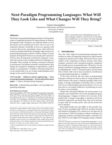
Design of segmented spherical/cylindrical probes12-sided 10 pentagons 2 hexagons
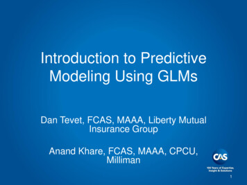
Segment a sphere and acquire 12 I-V tracesThe sphere is a low resolution modelof the cupcake shape, whereasthe cupcake shape is a low resolution modelof the sphere.Meierbachtol et al., ASEC 2017
CPIC, based on 1st-principles kinetic methodsand developed for curvilinear & multi-block mesh,maintains physics and geometric accuracy.The Curvilinear particle-in-cell (CPIC) plasma-material interactioncode has been modified for improved flexibility, and adapted herein studying spacecraft surface charging. The accuracy of the codephysics and geometric representation were verified against atheoretical solution for the charging of a perfectly conductingsphere. Numerical results demonstrating the capabilities of thecode in the case of simplistic spacecraft geometry were provided.Collin Meierbachtol, Daniil Svyatsky, Gian Luca Delzanno, Louis Vernon, and David Moulton2017 Numerical Simulations of Spacecraft Charging, Applied Space EnvironmentsConference: Measurements, Models, Testing, and Tools, 15-19 May 2017, Huntsville, AL.
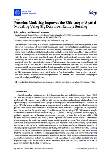
For a given charge on a conductor, E field is larger at edges and corners of a flatfaced segmented spherical probe, affecting the distribution of collected current.Richard Marchand computed the collected J/area using PTetra simulations for a floating ogiveshaped conductor immersed in a stationary unmagnetized Maxwellian plasma. The parametersassumed in the simulation are 100% H fully ionized plasma-electron density ion density 2.5x10⁹ m-3, Te Ti 0.1eV. Length of the ogive: 4-cm. Radius of the cross section at theback: 1cm. Floating potential -0.38V. The current density is in units of A/m 2. Total currentcollected 0. Negative current is collected at the edge and the tip of the ogive, where theelectric field (directed toward the ogive) is strongest, and positive current is collectedelsewhere where the surface is less sharp or less curved. Note also the large statistical errorsin the current collected per unit surface area. This is due to the near cancellation of positiveand negative current in this case where the total collected current is zero.
Publicity, recruitment, fundingConferences, workshops, agenciesAGU, APS-GEC, APS-DPP, Bringing Space Down to Earth (April), Active Experiments in Space,NSF, DOE-SC-FES, NASAProposal (inclusive participation)NSF-DOE Partnership, PI: Koepke, Co-PI: Marchand, Co-I: DemidovCommunication and organizationEstablish virtual presence, networking, and connectivity to achieve a fully integratedDevelopmental and Operational Test (DT/OT) approach in an inter-operable environmentPoint of contact: Mark.Koepke@mail.wvu.edu, 304-293-4912
ConclusionCompelled by high experimental feasibility and feature-rich predictions of telltale inhomogeneity where homogeneity otherwise abounds in conventionalmodeling, we conceive the proof-of-principle exercise to be a conductingsphere and a cylinder under the conditions of nonstationary, between-regimes,flowing plasma for a modeling-challenge paradigm based on design ofexperiments (DOE) methodology that merges numerical simulation and testing.After a proof-of-principle phase dedicated to generating evidence forstreamlining the Model/Simulation development process associated withspacecraft-environment interactions, such a methodology could serve toenable fundamental scientific research essential to accomplish the NASAmission or to certify performance-acceptability standards on instruments.
EndMott-Smith, H. M., and I. Langmuir 1926 Phys. Rev. 28, 727Allen, J. E., R. L. F. Boyd, and P. Reynolds 1957 Proc. Phys. Soc. London, Sect. B 70, 297Bernstein and Rabinowitz, 1959Laframboise, J. G. 1966 “Theory of spherical and cylindrical Langmuir probes in acollisionless Maxwellian plasma at rest,” Tech. Report UTIAS Report No. 100 (Univ. of TorontoInst. of Aerospace Studies); Laframboise, J. G., and L. W. Parker 1973 Phys. Fluids 16, 629Robertson, S. 2013 Plasma Phys Controlled Fusion 55, 093001Sanchez-Arriaga, G. 2013 A direct Vlasov code to study the non-stationary current collectionby a cylindrical Langmuir probe, Phys Plasmas 20, 013504Sanchez-Arriaga, G., and D. Pastor-Moreno 2014 Direct Vlasov simulations of electronattracting cylindrical Langmuir probes in flowing plasmas, Phys Plasmas 21, 073504Xin Chen and G. Sanchez-Arriaga 2017 Orbital motion theory and operational regimes forcylindrical emissive probes, Phys. Plasmas 24, 023504Leung, K. N., R. D. Collier, L. B. Marshall, T. N. Gallaher, W. H. Ingram, R. E. Kribel, and G.R. Taylor 1978 Characteristics of a multidipole ion source, Rev. Sci. Instrum. 49, 321.Coakley, P. and N. Hershkowitz 1979 Laboratory double layers, Phys Fluids 22, 1171Hershkowitz, N. 1985 Review of recent lab double layer experiments, Space Sci Rev 41, 351Batishchev O V 2009 Minihelicon plasma thruster, IEEE Trans Plasma Sci 37, 1563G. L. Delzanno, G. Lapenta, and M. Rosenburg 2004 Attractive potential around athermionically emitting microparticle, Phys. Rev. Lett. 92, 035002G. L. Delzanno and X.-Z. Tang 2014 Charging and heat collection by a positively charged dustgrain in a plasma, Phys. Rev. Lett. 113, 035002
The LANL SHIELDS Project: Space Hazards Induced near Earth by Large, Dynamic Storms: Understanding, Modeling, Predicting V. K. Jordanova, Space Science and Applications, LANL, at 2016 SHIELDS Workshop 4-8 April 2016 Whereas the SWMF (Space Weather Modeling Framework)-captures rapid