Transcription
Cisco 3825 and Cisco 3845Integrated Services Routerswith AIM-VPN/SSL-3FIPS 140-2 Non Proprietary Security PolicyLevel 2 ValidationVersion 1.7October 13, 2009 Copyright 2009 Cisco Systems, Inc.This document may be freely reproduced and distributed whole and intact including this Copyright Notice.
Table of Contents1INTRODUCTION . 31.11.21.31.4PURPOSE . 3REFERENCES . 3TERMINOLOGY . 3DOCUMENT ORGANIZATION . 32 CISCO 3825 AND 3845 ROUTERS . 52.1 THE 3825 CRYPTOGRAPHIC MODULE PHYSICAL CHARACTERISTICS . 52.2 THE CISCO 3845 CRYPTOGRAPHIC MODULE PHYSICAL CHARACTERISTICS . 92.3 ROLES AND SERVICES . 132.3.1. User Services . 132.3.2 Crypto Officer Services . 132.3.3 Unauthenticated Services . 142.3.4 Strength of Authentication . 142.4 PHYSICAL SECURITY . 152.5 CRYPTOGRAPHIC KEY MANAGEMENT . 192.6 SELF-TESTS . 282.6.1 Self-tests performed by the IOS image . 282.6.2 Self-tests performed by Safenet . 282.6.3 Self-tests performed by AIM . 293SECURE OPERATION OF THE CISCO 3825 OR 3845 ROUTER . 303.13.23.33.43.53.6INITIAL SETUP . 30SYSTEM INITIALIZATION AND CONFIGURATION . 30IPSEC REQUIREMENTS AND CRYPTOGRAPHIC ALGORITHMS . 31SSLV3.1/TLS REQUIREMENTS AND CRYPTOGRAPHIC ALGORITHMS. 31PROTOCOLS . 31REMOTE ACCESS . 31 Copyright 2009 Cisco Systems, Inc.2This document may be freely reproduced and distributed whole and intact including this Copyright Notice.
1Introduction1.1 PurposeThis document is the non-proprietary Cryptographic Module Security Policy for the Cisco 3825Integrated Services Router with AIM-VPN/SSL-3 and 3845 Integrated Services Routers Routerswith AIM-VPN/SSL-3 (Router Hardware Version: 3825 or 3845; Router Firmware Version: IOS12.4 (15) T3 and 12.4 (15) T10; AIM-VPN/SSL-3 Hardware Version 1.0, Board Revision 01).This security policy describes how the Cisco 3825 and 3845 Integrated Services Routers meetthe security requirements of FIPS 140-2, and how to operate the router with on-board cryptoenabled in a secure FIPS 140-2 mode. This policy was prepared as part of the Level 2 FIPS 1402 validation of the Cisco 3825 or 3845 Integrated Services Router.FIPS 140-2 (Federal Information Processing Standards Publication 140-2 — SecurityRequirements for Cryptographic Modules) details the U.S. Government requirements forcryptographic modules. More information about the FIPS 140-2 standard and validation programis available on the NIST website at http://csrc.nist.gov/groups/STM/index.html.1.2 ReferencesThis document deals only with operations and capabilities of the 3825 and 3845 routers withAIM modules in the technical terms of a FIPS 140-2 cryptographic module security policy. Moreinformation is available on the routers from the following sources:The Cisco Systems website contains information on the full line of Cisco Systemsrouters. Please refer to the following ters/index.htmlFor answers to technical or sales related questions please refer to the contacts listed onthe Cisco Systems website at www.cisco.com.The NIST Validated Modules ation.html) contains contact informationfor answers to technical or sales-related questions for the module.1.3 TerminologyIn this document, the Cisco 3825 or 3845 routers are referred to as the router, the module, or thesystem.1.4 Document OrganizationThe Security Policy document is part of the FIPS 140-2 Submission Package. In addition to thisdocument, the Submission Package contains:Vendor Evidence documentFinite State MachineOther supporting documentation as additional references Copyright 2009 Cisco Systems, Inc.3This document may be freely reproduced and distributed whole and intact including this Copyright Notice.
This document provides an overview of the routers and explains their secure configuration andoperation. This introduction section is followed by Section 2, which details the general featuresand functionality of the router. Section 3 specifically addresses the required configuration for theFIPS-mode of operation.With the exception of this Non-Proprietary Security Policy, the FIPS 140-2 ValidationSubmission Documentation is Cisco-proprietary and is releasable only under appropriate nondisclosure agreements. For access to these documents, please contact Cisco Systems. Copyright 2009 Cisco Systems, Inc.4This document may be freely reproduced and distributed whole and intact including this Copyright Notice.
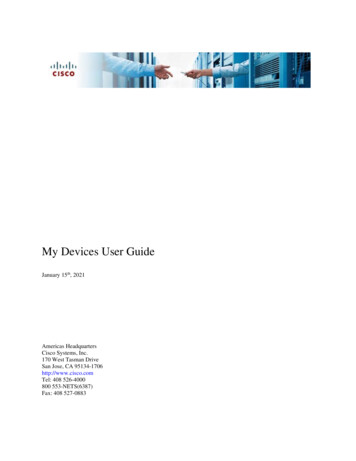
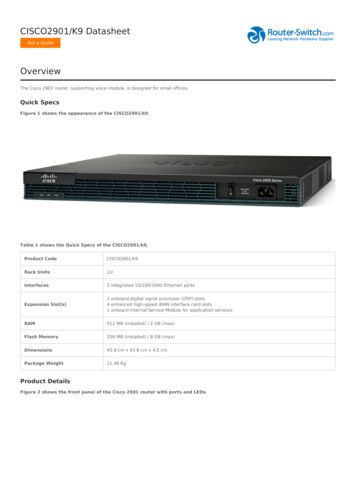
2 Cisco 3825 and 3845 RoutersBranch office networking requirements are dramatically evolving, driven by web and ecommerce applications to enhance productivity and merging the voice and data infrastructure toreduce costs. The Cisco 3825 and 3845 routers provide a scalable, secure, manageable remoteaccess server that meets FIPS 140-2 Level 2 requirements. This section describes the generalfeatures and functionality provided by the routers. The following subsections describe thephysical characteristics of the routers.2.1 The 3825 Cryptographic Module Physical CharacteristicsFigure 1 – The 3825 router caseThe 3825 Router is a multiple-chip standalone cryptographic module. The router has aprocessing speed of 500MHz. Depending on configuration, either the installed AIM-VPN/SSL-3module, the onboard Safenet chip or the IOS software is used for cryptographic operations.The cryptographic boundary of the module is the device’s case. All of the functionalitydiscussed in this document is provided by components within this cryptographic boundary.The interface for the router is located on the rear and front panels as shown in Figure 2 andFigure 3, respectively.Figure 2 – 3825 Rear Panel Physical Interfaces Copyright 2009 Cisco Systems, Inc.5This document may be freely reproduced and distributed whole and intact including this Copyright Notice.
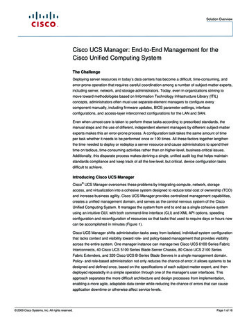
Figure 3 – 3825 Front Panel Physical InterfacesThe Cisco 3825 router features a console port, auxiliary port, dual Universal Serial Bus (USB)ports, four high-speed WAN interface card (HWIC) slots, two10/100/1000 Gigabit EthernetRJ45 ports, two Enhanced Network Module (ENM) slots, small form factor pluggable (SFP),redundant power supply (RPS) inlet, power inlet, and Compact Flash (CF) drive. The 3825router has slots for AIM-VPN/SSL-3 cards 1, and two Ethernet connections. Figure 2 shows therear panel and Figure 3 shows the front panel. The front panel consists of 12 LEDs: CF LED,SYS LED, ACT LED, SYS PWR LED, RPS LED, AUX PWR LED, AIM0 LED, AIM1 LED,PVDM0 LED, PVDM1 LED, PVDM2 LED, and PVDM3 LED.The back panel contains LEDs to indicate the status of the GE ports.The front panel contains the following: LEDs Power switch Power input CF drive USB portsThe rear panel contains the following: HWIC/WIC/VIC slots 0 and 1 Console port Auxiliary port GE ports ENM Ports SFP PortThe following tables provide more detailed information conveyed by the LEDs on the front andrear panel of the router:1The security policy covers the configuration in which one AIM card is used. Copyright 2009 Cisco Systems, Inc.6This document may be freely reproduced and distributed whole and intact including this Copyright Notice.
NameStateDescriptionSystemSolid GreenBlinking mal System Operation.Booting or in ROM monitor (ROMMON) mode.Powered, but malfunctionaing.Router is not receiving power.Power supply present and enabled.Power supply present and off or with failure.Power supply not present.Indicates IP phone power supply present.Indicates IP phone power supply present.IP phone power supply not present.System running on RPS PSU.System running on primary PSU.GreenOffSolid GreenBlinking enAmberOffGreenAmberOffGreenAmberOffSolid or blinking indicates packet activity.No interrupts or packet transfer occurring.Compact Flash present and enabled.Compact Flash accessed.Compact Flash not present.PVDM3 installed and initialized.PVDM3 installed and initialized error.PVDM3 not installed.PVDM2 installed and initialized.PVDM2 installed and initialized error.PVDM2 not installed.PVDM1 installed and initialized.PVDM1 installed and initialized error.PVDM1 not installed.PVDM0 installed and initialized.PVDM0 installed and initialized error.PVDM0 not installed.AIM1 present and enabled.AIM1 present with failure.AIM1 not installed.AIM0 present and enabled.AIM0 present with failure.AIM0 not installed.System PowerAuxiliary PowerRedundantPower SupplyActivityCompact FlashPVDM3PVDM2PVDM1PVDM0AIM1AIM0Table 1 – Cisco 3825 Front Panel IndicatorsNameStateSpeedGreen (Blinking)DescriptionBlinking frequency indicates port speed.LinkSolid GreenOffEthernet link is establishedNo link establishedTable 2 – Cisco 3825 Rear Panel IndicatorsThe following table describes the meaning of Ethernet LEDs on the rear panel:NameStateDuplexSolid GreenOff Copyright 2009 Cisco Systems, Inc.DescriptionFull-DuplexHalf-Duplex7This document may be freely reproduced and distributed whole and intact including this Copyright Notice.
SpeedLinkSolid GreenOffSolid GreenOff100 Mbps10 MbpsEthernet link is establishedNo link establishedTable 3 – Cisco 3825 Ethernet IndicatorsThe physical interfaces are separated into the logical interfaces from FIPS 140-2 as described inthe following table:Router Physical Interface10/100/1000 Ethernet LAN PortsHWIC PortsConsole PortAuxiliary PortENM SlotsSFPUSB Ports10/100/1000 Ethernet LAN PortsHWIC PortsConsole PortAuxiliary PortENM SlotsSFPUSB Ports10/100/1000 Ethernet LAN PortsHWIC PortsConsole PortAuxiliary PortENM SlotsSFP10/100/1000 Ethernet LAN LEDsSFP LEDAIM LEDsPVDM LEDsPower LEDSystem Activity LEDSystem LEDCompact Flash LEDAuxiliary Power LEDRPS LEDConsole PortAuxiliary PortUSB PortsPower PlugRedundant Power Supply PlugFIPS 140-2 Logical InterfaceData Input InterfaceData Output InterfaceControl Input InterfaceStatus Output InterfacePower InterfaceTable 4 – Cisco 3825 FIPS 140-2 Logical InterfacesThe CF card that stored the IOS image is considered an internal memory module, because theIOS image stored in the card may not be modified or upgraded. The card itself must never beremoved from the drive. Tamper evident seal will be placed over the card in the drive. Copyright 2009 Cisco Systems, Inc.8This document may be freely reproduced and distributed whole and intact including this Copyright Notice.
2.2 The Cisco 3845 Cryptographic Module Physical CharacteristicsFigure 4 – The 3845 router caseThe 3845 router with on-board crypto enabled is a multiple-chip standalone cryptographicmodule. The router has a processing speed of 650MHz. Depending on configuration, either theinstalled AIM-VPN/SSL-3 module, the onboard Safenet chip or the IOS software is used forcryptographic operations.The cryptographic boundary of the module is the device’s case. All of the functionalitydiscussed in this document is provided by components within this cryptographic boundary.The interfaces for the router are located on the front and rear panel as shown in Figure 4 andFigure 5, respectively.Figure 5 – Cisco 3845 Front Panel Physical Interfaces Copyright 2009 Cisco Systems, Inc.9This document may be freely reproduced and distributed whole and intact including this Copyright Notice.
Figure 6 – Cisco 3845 Rear Panel Physical InterfacesThe Cisco 3845 router features a console port, auxiliary port, dual Universal Serial Bus (USB)ports, four high-speed WAN interface card (HWIC) slots, two10/100/1000 Gigabit EthernetRJ45 ports, four Enhanced Network Module (ENM) slots, small form factor pluggable (SFP),power inlets, and Compact Flash (CF) drive. The 3845 router has slots for AIM-VPN/SSL-3cards 2, and two Ethernet connections. The Figure 4 shows the front panel and Figure 5 shows therear panel. The front panel consists of 7 LEDs: CF LED, PVDM0 LED, PVDM1 LED, PVDM2LED, PVDM3 LED, AIM0 LED, and AIM1 LED. The back panel consists of 6 LEDs: SYSLED, ACT LED, SYS PWR1 LED, AUX PWR1 LED, SYS PWR2 LED, and AUX PWR2LED.The front panel contains the following: LEDs Power switch Power inputThe rear panel contains the following: CF drive USB ports Console and Auxiliary ports HWIC ports LEDs HWIC ports GE ports SFP port ENM slots2The security policy covers the configuration in which one AIM card is used. Copyright 2009 Cisco Systems, Inc.10This document may be freely reproduced and distributed whole and intact including this Copyright Notice.
The following tables provide more detailed information conveyed by the LEDs on the front andrear panel of the router:NameStateDescriptionSystemSolid GreenBlinking ffGreenAmberOffGreenOffSolid GreenBlinking enAmberOffGreenAmberOffGreenAmberOffNormal System Operation.Booting or in ROM monitor (ROMMON) mode.Powered, but malfunctionaing.Router is not receiving power.Power1 supply present and enabled.Power1 supply present and off or with failure.Power1 supply not present.Indicates IP phone power1 supply present.Indicates IP phone power1 supply present.IP phone power1 supply not present.Power2 supply present and enabled.Power2 supply present and off or with failure.Power2 supply not present.Indicates IP phone power2 supply present.Indicates IP phone power2 supply present.IP phone power2 supply not present.Solid or blinking indicates packet activity.No interrupts or packet transfer occurring.Compact Flash present and enabled.Compact Flash accessed.Compact Flash not present.PVDM3 installed and initialized.PVDM3 installed and initialized error.PVDM3 not installed.PVDM2 installed and initialized.PVDM2 installed and initialized error.PVDM2 not installed.PVDM1 installed and initialized.PVDM1 installed and initialized error.PVDM1 not installed.PVDM0 installed and initialized.PVDM0 installed and initialized error.PVDM0 not installed.AIM1 present and enabled.AIM1 present with failure.AIM1 not installed.AIM0 present and enabled.AIM0 present with failure.AIM0 not installed.System Power1AuxiliaryPower1System Power2AuxiliaryPower2ActivityCompact FlashPVDM3PVDM2PVDM1PVDM0AIM1AIM0Table 5 – Cisco 3845 Front Panel IndicatorsThe following table describes the meaning of Ethernet LEDs on the front panel:NameStateSpeedOne Blinking GreenTwo Blinking GreenThree Blinking Green Copyright 2009 Cisco Systems, Inc.Description10 Mbps100 Mbps1000Mbps11This document may be freely reproduced and distributed whole and intact including this Copyright Notice.
LinkSFPSolid GreenOffSolid GreenOffEthernet link is establishedNo link establishedSFP fiber link is establishedNo link establishedTable 6 – Cisco 3845 Ethernet IndicatorsThe physical interfaces are separated into the logical interfaces from FIPS 140-2 as described inthe following table:Router Physical Interface10/100/1000 Ethernet LAN PortsHWIC PortsConsole PortAuxiliary PortENM SlotsSFPUSB Ports10/100/1000 Ethernet LAN PortsHWIC PortsConsole PortAuxiliary PortENM SlotsSFPUSB Ports10/100/1000 Ethernet LAN PortsHWIC PortsConsole PortAuxiliary PortENM SlotsSFP10/100/1000 Ethernet LAN LEDsSFP LEDAIM LEDsPVDM LEDsSystem Power LEDsSystem Activity LEDSystem LEDCompact Flash LEDAuxiliary Power LEDsConsole PortAuxiliary PortUSB PortsPower PlugFIPS 140-2 Logical InterfaceData Input InterfaceData Output InterfaceControl Input InterfaceStatus Output InterfacePower InterfaceTable 7 – Cisco 3845 FIPS 140-2 Logical InterfacesThe CF card that stored the IOS image is considered an internal memory module. The reason isthe IOS image stored in the card cannot be modified or upgraded. The card itself must never beremoved from the drive. Tamper evident seal will be placed over the card in the drive. Copyright 2009 Cisco Systems, Inc.12This document may be freely reproduced and distributed whole and intact including this Copyright Notice.
2.3 Roles and ServicesAuthentication in Cisco 3825 and 3845 is role-based. There are two main roles in the router thatoperators can assume: the Crypto Officer role and the User role. The administrator of the routerassumes the Crypto Officer role in order to configure and maintain the router using CryptoOfficer services, while the Users exercise only the basic User services. The module supportsRADIUS and TACACS for authentication. A complete description of all the management andconfiguration capabilities of the router can be found in the Performing Basic SystemManagement manual and in the online help for the router.2.3.1. User ServicesUsers enter the system by accessing the console port with a terminal program or IPSec protectedtelnet or SSH session to a LAN port. The IOS prompts the User for username and password. Ifthe password is correct, the User is allowed entry to the IOS executive program.The services available to the User role consist of the following:Status FunctionsView state of interfaces and protocols, version of IOS currentlyrunning.Network FunctionsConnect to other network devices through outgoing telnet, PPP, etc.and initiate diagnostic network services (i.e., ping, mtrace).Adjust the terminal session (e.g., lock the terminal, adjust flowcontrol).Display directory of files kept in flash memory.Negotiation and encrypted data transport via SSL/TLS.Negotiation and encrypted data transport via EASY VPN.Negotiation and encrypted data transport via Get VPN.Terminal FunctionsDirectory ServicesSSL-TLS/VPNEASY VPNGet VPN2.3.2 Crypto Officer ServicesDuring initial configuration of the router, the Crypto Officer password (the “enable” password) isdefined. A Crypto Officer can assign permission to access the Crypto Officer role to additionalaccounts, thereby creating additional Crypto Officers.The Crypto Officer role is responsible for the configuration and maintenance of the router.The Crypto Officer services consist of the following:Configure the routerDefine network interfaces and settings, create command aliases, setthe protocols the router will support, enable interfaces and networkservices, set system date and time, and load authenticationinformation. Copyright 2009 Cisco Systems, Inc.13This document may be freely reproduced and distributed whole and intact including this Copyright Notice.
Define Rules and Filters Create packet Filters that are applied to User data streams on eachinterface. Each Filter consists of a set of Rules, which define a setof packets to permit or deny based on characteristics such asprotocol ID, addresses, ports, TCP connection establishment, orpacket direction.View the router configuration, routing tables, active sessions, useView Status Functionsgets to view SNMP MIB statistics, health, temperature, memorystatus, voltage, packet statistics, review accounting logs, and viewphysical interface status.Log off users, shutdown or reload the router, erase the flashManage the routermemory, manually back up router configurations, view completeconfigurations, manager user rights, and restore routerconfigurations.Set up the configuration tables for IP tunneling. Set preshared keysSet Encryption/Bypassand algorithms to be used for each IP range or allow plaintextpackets to be set from specified IP address.Bypass ModeThe routers implement an alternating bypass capability, in which some connections may becryptographically authenticated and encrypted while others may not. Two independent internalactions are required in order to transition into each bypass state: First, the bypass state must beconfigured by the Crypto Officer using “match address ACL-name " sub-command undercrypto map which defines what traffic is encrypted. Second, the module must receive a packetthat is destined for an IP that is not configured to receive encrypted data. The configuration tableuses an error detection code to detect integrity failures, and if an integrity error is detected, themodule will enter an error state in which no packets are routed. Therefore, a single error in theconfiguration table cannot cause plaintext to be transmitted to an IP address for which it shouldbe encrypted.2.3.3 Unauthenticated ServicesThe services available to unauthenticated users are: Viewing the status output from the module’s LEDs Powering the module on and off using the power switch Sending packets in bypass2.3.4 Strength of AuthenticationThe security policy stipulates that all user passwords must be 8 alphanumeric characters, so thepassword space is 2.8 trillion possible passwords. The possibility of randomly guessing apassword is thus far less than one in one million. To exceed a one in 100,000 probability of asuccessful random password guess in one minute, an attacker would have to be capable of 28million password attempts per minute, which far exceeds the operational capabilities of themodule to support. Copyright 2009 Cisco Systems, Inc.14This document may be freely reproduced and distributed whole and intact including this Copyright Notice.
When using RSA based authentication, RSA key pair has modulus size of 1024 bit to 2048 bit,thus providing between 80 bits and 112 bits of strength. Assuming the low end of that range, anattacker would have a 1 in 280 chance of randomly obtaining the key, which is much strongerthan the one in a million chance required by FIPS 140-2. To exceed a one in 100,000 probabilityof a successful random key guess in one minute, an attacker would have to be capable ofapproximately 1.8x10²¹ attempts per minute, which far exceeds the operational capabilities ofthe modules to support.When using preshared key based authentication, the security policy stipulates that all presharedkeys must be 8 alphanumeric characters, so the key space is 2.8 trillion possible combinations.The possibility of randomly guessing this is thus far less than one in one million. To exceed aone in 100,000 probability of a successful random guess in one minute, an attacker would haveto be capable of 28 million attempts per minute, which far exceeds the operational capabilities ofthe module to support.2.4 Physical SecurityThe router is entirely encased by a metal, opaque case. The rear of the unit contains auxiliaryport, console port, Gigabit Ethernet ports, HWIC ports, and ENM slots. The front of the unitcontains USB connectors, CF drive, power inlets, power switch, and LEDs. The top, side, andfront portion of the chassis can be removed to allow access to the motherboard, memory, AIMslots, and expansion slots.The Cisco 3825 and Cisco 3845 routers require that a special opacity shield be installed over theside air vents in order to operate in FIPS-approved mode. The shield decreases the surface areaof the vent holes, reducing visibility within the cryptographic boundary to FIPS-approvedspecifications.Install the opacity plates as specified in the pictures below: Copyright 2009 Cisco Systems, Inc.15This document may be freely reproduced and distributed whole and intact including this Copyright Notice.
Figure 7 – 3825 – Opacity Shield PlacementFigure 8 – 3845 – Opacity Shield PlacementOnce the router has been configured in to meet FIPS 140-2 Level 2 requirements, the routercannot be accessed without signs of tampering. To seal the system, apply serialized tamperevidence labels as follows:For Cisco 3825:1. Clean the cover of any grease, dirt, or oil before applying the tamper evidencelabels. Alcohol-based cleaning pads are recommended for this purpose. Thetemperature of the router should be above 10 C.2. Tamper evidence label A shall be placed so that one half of the label covers thetop of the front panel and the other half covers the enclosure.3. Tamper evidence label B shall be placed so that one half of the label covers thebottom of the front panel and the CF card and the other half covers the enclosure.4. Tamper evidence labels C and D should be placed so that the one half of the labelcovers the enclosure and the other half covers the left and right upper ENM slots.5. Tamper evidence label E should be placed so that the one half of the label coversthe lower right ENM slot and the other half covers the enclosure.6. Tamper evidence label F should be placed so that the one half of the label coversthe left upper and lower HWIC slots and the other half covers the enclosure.7. Tamper evidence label G should be placed so that the one half of the label coversthe right upper and lower HWIC slots and the other half covers the enclosure. Copyright 2009 Cisco Systems, Inc.16This document may be freely reproduced and distributed whole and intact including this Copyright Notice.
8. Tamper evidence labels H and I should be placed on the top and bottom of theopacity shield such that the one half of each label covers opacity shield and theother half covers the enclosure.9. The labels completely cure within five minutes.Figures 9, 10 and 11 show the tamper evidence label placements for the 3825. Note thateach diagram only shows certain label placement locations.Figure 9 – 3825 Tamper Evident Label Placement (Front View)Figure 10 – 3825 Tamper Evident Label Placement (Back View)Figure 11 - 3825 Tamper Evident Label Placement (Side View)For Cisco 3845: Copyright 2009 Cisco Systems, Inc.17This document may be freely reproduced and distributed whole and intact including this Copyright Notice.
1. Clean the cover of any grease, dirt, or oil before applying the tamper evidencelabels. Alcohol-based cleaning pads are recommended for this purpose. Thetemperature of the router should be above 10 C.2. Tamper evidence labels A and B should be placed so that one half of the labelcovers the front panel and the other half covers the enclosure.3. Tamper evidence label C should be placed so that one half of the label covers theleft upper and lower ENM modules and the other half covers the enclosure.4. Tamper evidence labels D and E should be placed so that one half of each labelcovers the side of right ENM modules and the other half covers the enclosure.5. Tamper evidence labels F, G, H and I should be placed so that one half of eachlabel covers the top side of HWIC modules and the other half covers theenclosure.6. Tamper evidence label J should be placed over the CF slot.7. Tamper evidence labels K, L, M and N should be placed on each of the opacityshields so that one half of each label covers the opacity shield and the other halfcovers the enclosure.8. The labels completely cure within five minutes.Figures 12, 13 and 14 show the tamper evidence label placements for the 3845.Figure 12 – Cisco 3845 Tamper Evident Label Placement (Front View)Figure 13 – Cisco 3845 Tamper Evident Label Placement (Back View) Copyright 2009 Cisco Systems, Inc.18This document may be freely reproduced and distributed whole and intact including this Copyright Notice.
Figure 14 - Cisco 3845 Tamper Evident Label Placement (Side Views)The tamper evidence seals are produced from a special thin gauge vinyl with self-adhesivebacking. Any attempt to open the router will damage the tamper evidence seals or the material ofthe module cover. Since the tamper evidence seals have non-repeated serial numbers, they can beinspected for damage and compared against the applied serial numbers to verify that the modulehas not been tampered. Tamper evidence seals can also be inspected for signs of tampering,which include the following: curled corners, bubbling, crinkling, rips, tears, and slices. The word“OPEN” may appear if the label was peeled back.2.5 Cryptographic Key ManagementThe router securely administers both cryptographic keys and other critical security parameterssuch as passwords. The tamper evidence seals provide physical protection for all keys. All keysare also protected by the password-protection on the Crypto Officer role login, and can bezeroized by the Crypto Officer. All zeroization consists of overwriting the memory that storedthe k
The 3845 router with on-board crypto enabled is a multiple-chip standalone cryptographic module. The router has a processing speed of 650MHz. Depending on configuration, either the installed AIM-VPN/SSL-3 module, the onboard Safenet chip