Transcription
Lecture 6 – Introduction to theATmega328 and ArdunioCSE P567
Outline Lecture 6 ATmega architecture and instruction setI/O pinsArduino C languageLecture 7 Controlling Time Lecture 8 Interrupts and TimersGuest lecture – Radio communicationLecture 9 Designing PID Controllers
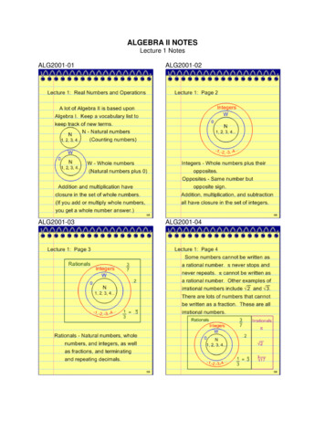
AVR Architecture
AVR Architecture Clocks and PowerBeyond scope of thiscourse
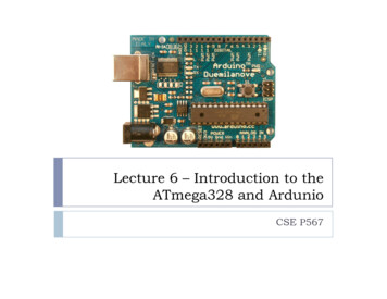
AVR Architecture CPU Details coming
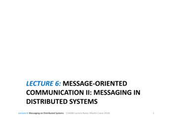
AVR Architecture Harvard architectureFlash – program memory SRAM – data memory 32K2KEEPROM For long-term dataOn I/O data bus
Memory Flash (32K) (15-bit addresses) Program memory – read onlyNon-volatileAllocate data to Flash using PROGMEM keyword SRAM (2K) see documentationTemporary values, stack, etc.VolatileLimited space!EEPROM (1K) Long-term datasee documentation on EEPROM library
AVR CPU Instruction Fetchand Decode
AVR CPU ALU Instructions
AVR CPU I/O and specialfunctions
AVR Register File 32 8-bit GP registersPart of SRAM memory space
Special Addressing Registers X,Y and Z registers 16-bit registers made using registers 26 – 31Support indirect addressing
AVR Memory Program memory – Flash Data memory - SRAM
Addressing Modes Direct registeraddressing
Addressing Modes Direct I/O addressing
Addressing Modes Direct data memory addressing
Addressing Modes Direct data memory with displacement addressing
Addressing Modes Indirect data memory addressing
Addressing Modes Indirect data memory addressing with pre-decrement
Addressing Modes Indirect data memory addressing with post-increment
Addressing Modes Program memory addressing (constant data)
SRAM Read/Write Timing
Stack Pointer Register Special register in I/O space [3E, 3D] Enough bits to address data spaceInitialized to RAMEND (address of highest memory address)Instructions that use the stack pointer
Program Status Register (PSR) \Status bits set by instructions/Checked by Branch/Skipinstructions I – Global interrupt enableT – Flag bitH – Half carry (BCD arithmetic)S – SignV – OverflowN – NegativeZ – ZeroC – Carry
Simple 2-Stage Pipeline Branch/Skip?
Single-Cycle ALU Instructions Most instructions execute in one cycleMakes program timing calculations (relatively) easy No cache misses1 clock/instruction
Addressing Modes JMP, CALL – Direct Program Memory Addressing
Addressing Modes IJMP, ICALL – Indirect program memory addressing
Addressing Modes RJMP, RCALL – Relative program memory addressing
Arithmetic Instructions
Logical Instructions
Jump and Call Instructions
Skip and Branch Instructions
Skip and Branch (cont)
Move, Load
Store
Load/Store Program Memory
Move, I/O, Push/Pop
Shift and Bit Instructions
Bit Instructions (cont)
AVR Architecture Three timersVery flexible Choose clock rateChoose “roll-over” valueGenerate interruptsGenerate PWM signals (represent 8-bit value withusing a clock signal)More in next lecture
Arduino Timing Functions delay(ms) delayMicroseconds(us) wait for us microseconds before continuingunsigned long millis( ) wait for ms milliseconds before continuingreturn number of milliseconds since program startedunsigned long micros( ) return number of microseconds since program startedresolution of 4 microseconds
AVR Architecture Interface to pinsEach pin directlyprogrammable Program directionProgram valueProgram pull-upsSome pins are special Analog vs. DigitalClocksReset
I/O Ports 3 8-bit Ports (B, C, D)Each port controlled by 3 8-bit registers Each bit controls one I/O pinDDRx – Direction register PINx – Pin input value Defines whether a pin is an input (0) or and output (1)Reading this “register” returns value of pinPORTx – Pin output value Writing this register sets value of pin
Pin Circuitry
Pin InputDDRx 0offPORTxPINx
Synchronization Timing Note: Takes a clock cycle for data output to be reflectedon the input
Pin OutputDDRx 1onPORTxPINx
Pin Input – PORT controls pullupDDRx 0offPORTxPINx
I/O Ports Pullups If a pin is an input (DDRxi 0): PORTxi 0 – pin is floatingPORTxi 1 – connects a pullup to the pin Keeps pin from floating if noone drivingAllows wired-OR busIndividual bits can be set cleared using bit-opsA bit can be toggled by writing 1 to PINxi SBI instruction e.g.
I/O Protection
Arduino Digital and Analog I/O Pins Digital pins: Pins 0 – 7: PORT D [0:7]Pins 8 – 13: PORT B [0:5]Pins 14 – 19: PORT C [0:5] (Arduino analog pins 0 – 5)digital pins 0 and 1 are RX and TX for serial communicationdigital pin 13 connected to the base board LEDDigital Pin I/O Functions pinMode(pin, mode) digitalWrite(pin, value) Sets pin to INPUT or OUTPUT modeWrites 1 bit in the DDRx registerSets pin value to LOW or HIGH (0 or 1)Writes 1 bit in the PORTx registerint value digitalRead(pin) Reads back pin value (0 or 1)Read 1 bit in the PINx register
Arduino Analog I/O Analog input pins: 0 – 5Analog output pins: 3, 5, 6, 9, 10, 11 (digital pins)Analog input functions int val analogRead(pin)Converts 0 – 5v. voltage to a 10-bit number (0 – 1023)Don’t use pinModeanalogReference(type) Used to change how voltage is converted (advanced)Analog output analogWrite(pin, value) value is 0 – 255Generates a PWM output on digital pin (3, 5, 6, 9, 10, 11)@490Hz frequency
AVR Architecture Analog inputsConvert voltage to a10-bit digital valueCan provide referencevoltages
PWM – Pulse Width Modulation Use one wire to represent a multi-bit value A clock with a variable duty cycleDuty cycle used to represent value We can turn it into a analog voltage using an integrating filter
Port Special Functions Lots of special uses for pins Clock connectionsTimer connections e.g. comparator output for PWMInterruptsAnalog referencesSerial bus I/Os USARTPCI
Reading and Writing Pins Directly Only one pin can be changed using the Arduino I/Ofunctions To change multiple pins simultaneously, directly read/writethe pin registers Setting multiple pins takes time and instructionsDDR{A/B/C}PORT{A/B/C}PIN{A/B/C}e.g. to set all digital pins 0 – 7 to a value: PORTD B01100101;
AVR Architecture Special I/O support Serial protocolsUses special pinsUses timersBeyond scope of thiscourse
Arduino C Programs Arduino calls these “sketches” Program structure Header: declarations, includes, etc.setup()loop()Setup is like Verilog initial Basically C with librariesexecutes once when program startsloop() is like Verilog always continuously re-executed when the end is reached
Blink Programint ledPin 13;// LED connected to digital pin 13// The setup() method runs once, when the sketch startsvoid setup(){// initialize the digital pin as an output:pinMode(ledPin, OUTPUT);}// the loop() method runs over and over again,// as long as the Arduino has powervoid loop(){digitalWrite(ledPin, HIGH);delay(1000);digitalWrite(ledPin, LOW);delay(1000);}////////set the LED onwait for a secondset the LED offwait for a second
The Arduino C Main Programint main(void){init();setup();for (;;)loop();return 0;}
Arduino Serial I/O Communication with PC via USB serial line Use the Serial Monitor in the IDEOr set up a C or Java (or you-name-it) interfaceExample Serial library calls Serial.begin(baud-rate) Serial.println(string)int foo Serial.read() 9600 defaultRead one byte (input data is buffered)See documentation for more
Example Program
Arduino Digital and Analog I/O Pins Digital pins: Pins 0 – 7: PORT D [0:7] Pins 8 – 13: PORT B [0:5] Pins 14 – 19: PORT C [0:5] (Arduino analog pins 0 – 5) digital pins 0 and 1 are RX and TX for serial communication digital pin 13 connected to the ba