Transcription
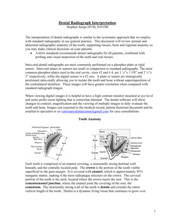
Dental Radiograph InterpretationStephen Juriga DVM, DAVDCThe interpretation of dental radiographs is similar to the systematic approach that we employwith standard radiography in our general practice. This document will review normal andabnormal radiographic anatomy of the tooth, supporting tissues, bone and regional anatomy soyou may make clinical decisions on your patients. AAHA standards recommends dental radiographs for all patients, combined withprobing and visual inspection of the teeth and oral tissues.Intra-oral dental radiographs are most commonly performed on a phosphor plate or rigidsensor. Intra-oral plates or sensors are small in comparison to standard radiographs. The mostcommon phosphor plates used in the oral cavity, sizes #2 and # 4, are 1 ¼”x 1 5/8” and 2 ¼”x3” respectively, while the digital sensor is a #2 size. A plate or sensor are strategicallypositioned intra-orally allowing you to isolate the tooth and bone without superimposition ofthe contralateral dentition. These images will have greater resolution when compared withstandard radiograph images.When viewing digital images it is helpful to have a high contrast monitor mounted at eye leveland some prefer room lighting that is somewhat dimmed. The dental software will allowchanges in contrast, magnification and the viewing of multiple images to fully evaluate thetooth and bone. Images can exported to the medical record, patient dismissal document and beemailed to specialist or us veterinarydentalcenter@gmail.com for case consultations.Tooth AnatomyEach tooth is comprised of an enamel covering, a structurally strong dentinal wallbeneath, and the centrally located pulp. The crown is the portion of the tooth visiblesuperficial to the gum margin. It is covered with enamel, which is approximately 95%inorganic matter, making it the most radiopaque structure on the crown. The cervicalportion of the tooth is the neck, located where the crown meets the root. This is thecementoenamel junction, where the enamel joins the covering of the root, thecementum. The structurally strong wall of the tooth is dentin and extends the entirevertical length of the tooth. Dentin is a dynamic living tissue that continues to grow over1
a pet’s lifetime. It is composed of approximately 70% inorganic material and is thereforeless radiopaque than the enamel. In the center of the tooth is the pulp (blood and nervesupply of the tooth) which will appear as the radiolucent center of the tooth. Initially, thepulp canal is very large and the dentinal wall very thin. As the tooth matures the wallthickens (dentin), the root lengthens, and the apex closes between 9 months and 12months of age. This maturation of the tooth can be used to assess viability whencompared to the contralateral tooth.The supportive tissues of the tooth is the periodontium. Four tissues comprise theperiodontium: the gingiva (gum tissue), cementum, periodontal ligament, and alveolarbone. For radiographic purposes the periodontal ligament is our landmark. Theperiodontal ligament (PDL) is comprised of strong connective tissue fibers that suspendthe tooth, like a shock absorber, in the alveolar socket. The PDL will appear as a thin,radiolucent (dark) line surrounding the root of the tooth. The PDL attaches to thealveolar bone, which is a dense cortical bone lining the socket or lamina dura. The PDLwill appear wider in the young pet and will narrow with age.Alveolar bone is slightly more radiolucent than tooth roots and appears mottled. Thelamina dura is radiographically visible as a radiopaque line that represents the densecompact bone lining the alveolus. The alveolar margin is the cortical bone that extendswithin 1-2 mm apically to the cemetoenamel junction. This bone tends to be pointed inthe rostral regions and somewhat flat as we move caudally in the dental arcade.Furcational bone is another important region to evaluate. This is the bone that liesbetween the roots of individual multirooted teeth.Normal Dental Radiographic Anatomy2
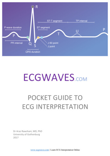
The key to successful interpretation of dental radiographs is to develop a workingknowledge of dental anatomy and the common pathologic conditions unique to dentistry.A systematic approach should be taken with each radiographic image.1. Start at one lateral margin of the radiograph and move to the other. Assess eachcrown and the general relationship of all tooth structures relative to the adjacentteeth.2. The level of periodontal bone should be evaluated (interproximal bone andfurcation bone).3. The periodontal ligament space and bone surrounding each tooth should beassessed. The bone density as well as integrity of the lamina dura should be noted.4. The pulp chamber of each tooth should be evaluated as well as pulp canalsymmetry between teeth.5. Normal anatomical landmarks should be identified. These include the nasalcavity, mandibular symphysis, mandibular canal, palatine fissures, and mentalforamen. These all are considered in the diagnosis of disease as well as treatmentplanning (extractions )Mandibular canal Ventral cortex Furcational bone Interproximal bone Periodontal ligament Root canalLamina Dura3
Image Orientation and AssessmentWhen evaluating dental radiographs we make two assumptions:1. The plate/sensor was placed intra-orally (if an extra-oral technique is used theimage should be “flipped” and annotated).2. The plate/sensor was positioned correctly in the oral cavity so it was facing theradiographic tube head.The image will appear on the monitor and only require rotation for assessment. First, wemust first determine if the view is a maxillary or mandibular view based on commonlandmarks: The mandibular views will have single or double rooted teeth in a dense alveolarsocket with a dense ventral cortex. The incisor and canine teeth will also reside inthis bone and be separated by a radiolucent midline or mandibular symphysis. Forviewing, the mandibular teeth roots are pointed down and crowns upward.Caudal mandible Rostral MandibleThe bone of the maxillary view appears more uniformly dense and extends farbeyond the apex of the teeth (palatine bone, nasal passages and sinuses). Theincisor and canine teeth of the maxilla will have two symmetrical radiolucent ovalstructures which represent the palatine fissures. For viewing, the maxillary viewsshould have the roots oriented upward and crowns downward.Canine MaxillaFeline MaxillaNext, we must ascertain rostral from caudal (In dental terms: mesial from distal), byvisualizing the tooth & root anatomy. Quick anatomy note: The incisors, canine teeth, and first premolar (if present) are single rootedteeth. In the maxilla, the 2nd and 3rd premolars are double rooted and the 4thpremolar, 1st and 2nd molars are triple rooted teeth. In the mandible, the 2ndpremolar distally to the 2nd molar are double rooted teeth.4
An acrylic dental model is a useful aid at this time. In the maxilla try toidentify triple and double rooted teeth on the image. Remember, that thetriple rooted teeth are distal or caudal. In the mandible use the large firstmolar as a landmark and remember that the crown is larger mesially (use youracrylic model).Finally, we are ready to determine right from left, so you may identify the teeth that areon the radiograph. While viewing the radiograph, imagine where the patients nose ispointing and visualize yourself looking at the patient face to face. The direction the noseis pointing is the side you are viewing!FOLLOW THESE 3 SIMPLE STEPS:1. View the digital image on the monitor.2. Rotate the imagea. Maxilla roots point upb. Mandible roots point down3. Decide which way the nose of the patient is.a. Visualize the number and size of the roots, crown shape, and sizeof the teethb. Imagine facing the patient, the direction the nose is pointing is theside you are viewing.Right MaxillaLeft Maxilla- young dogRight MandibleLeft Mandible5
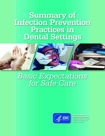
Normal Anatomy TipsWhen imaging the rostral maxillary area, the paired radiolucent areas distal to theintermediate incisors are the palatine fissures (yellow arrow). Also, the maxillarypremolar and molar area contains a radiodense line apical to the roots (green arrow).This represents the junction of the vertical body of the maxilla and the palatine process(hard palate) of the maxilla. A skull model is helpful to identify these structures andtheir location relative to the teeth.Palatine FissuresThe radiolucent line between the central incisor teeth is the fibrocartilagenousmandibular symphysis (yellow arrow). Radiographic views of the mandibular molarand premolar teeth have several normal anatomic findings that may be misinterpreted aspathologic lesions. A horizontal radiolucent line near above ventral cortex is themandibular canal (red arrow). Three circular radiolucent areas are usually present inthe area of mandibular premolars are the mental foramina (rostral, middle, and caudalgreen arrow)).Mandibular symphysisMental foramenMandibular canal6
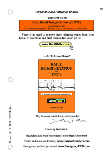
Periodontal pocket or bone loss Periodontal DiseasePeriodontal disease causes resorption of the bone resulting in the level of bone being 2 mm below the cementoenamel junction or a loss of bone density in the furcationregion. Remember, forty percent of the bone has to be destroyed in a region before thelysis becomes evident radiographically. Therefore, radiographic findings generallyunderestimate bone loss. Bony pockets may also be under diagnosed if the bone loss isconfined to the lingual, palatal, or facial (buccal) surfaces and therefore hidden bysuperimposition of bone or tooth. Always interpret radiographs bearing in mind theresults of the oral examination and probing. Brachycephalic breeds have tooth rotation/crowding and imaging with cone beam CT allows improved, 3D assessment of teeth andbone in these breeds.Horizontal bone loss (yellow arrows) occurs when there is generalized bone loss of asimilar level across group of teeth. With horizontal bone loss, the buccal, lingual, andinterdental bone will undergo resorption. Vertical (angular) bone loss (red arrows)occurs in an apical direction along a specific root surface with little effect to thesurrounding bone of the region.7
Furcation bone loss is visualized by a loss of bone density in the region of the furcation.Remember to correlate your periodontal probe findings with your radiographic findingsas these lesions are underestimated radiographically (Class 1 & 2). Class 3 disease resultsin total bone loss and will appear as a radiolucent area and the probe will pass throughthis region.Feline Chronic Alveolar Osteomyeltis clinically appears as buccal bone expansion(arrows) of the maxillary or mandibular canine teeth. Radiographically these lesionsappear as expansive buccal bone growth and vertical bone loss (infrabony pocket) alongthe root surface. The radiographic changes should be evaluated in the maxillary occlusalview as well as oblique images.Oblique viewOcclusal viewTooth Trauma Endodontic DiseaseRadiography is essential for the evaluation of a discolored tooth, abrasively worn tooth orfractured tooth. The pulp is the radiolucent canal or cavity with the tooth (root andcrown) and represents the blood vessels and nerves of the tooth. Endodontic disease maybe diagnosed radiographically based on bone or tooth changes.Intact caninePulp locationFractured canine w/ lucency8
Tooth viability: As a tooth matures, secondary dentin is produced causing a decrease inpulp canal width. When a tooth becomes non-vital, the production of dentin stops,resulting in a wider root canal than the surrounding vital teeth (this takes 6 months-yearto become visible). The most accurate assessment is to compare the affected tooth to thecontralateral tooth. Every attempt should be made to expose the views at the same anglewhen comparing teeth since root canals (especially in canine teeth) are not perfectcylinders. A change in the beam angle may affect the apparent canal diameter.Recent fracture withSymmetrical pulp canalsFracture 12 months prior noteAsymmetry- Non-vial toothPeriapical disease is a pathologic process surrounding the apex of one or more roots.Radiographically periapical disease may appear as a widened periodontal ligament space,a thickened or discontinuous lamina dura, or radiolucent (halo) defect at the apex (yellowarrows). This may occur when the inflammatory/infectious agents extend through theapex of the tooth resulting in osteoclastic bone resorption. Chronic lesions or infectionmay have a more radiopaque appearance and are described as osteosclerosis orcondensing osteitis (Bottom right radiograph). Use your probe to evaluate the tooth forpulp exposure of the crown or deep periodontal pocket on these questionable teeth.Condensing osetitis9
Tooth Resorptive Lesions (TR)This disease is common in cats, affecting 50% of cats by age 5. Radiographically, teethwith type I lesions (green arrows) have normal root density in some areas as comparedto surrounding teeth and a well-defined periodontal ligament space around the tooth.These teeth will often have a definable root canal in the intact part of the tooth. Type Ilesions typically retain a viable root canal system and require complete extraction ofall the root structure.Intact root- Type 1**Resorbing and intact rootThe radiographic appearance of teeth with type II lesions (yellow arrows) shows rootsthat have undergone variable replacement resorption and have a different radiographicdensity as compared to normal tooth roots. These teeth will have a loss of periodontalligament space (dentoalveolar ankylosis), decrease in root density and loss of visible rootcanal. Type II lesions, have no periodontal ligament, root ankylosis, root resorptionand maybe treated with crown/root amputation therapy.Clinical photos for review10
Although less common, tooth resorption in dogs are similar to feline lesions: painfuland progressive. These teeth require extraction therapy. The roots are fragile and arechallenging cases. In some cases resorbing roots must be retained, however there are nolong term studies on root retention/resorption in canine patients. Cone beam CT offersimproved imaging of early lesions by elimination superimposition of root or crownstructures.Root and tooth resorption in a dogTooth ImpactedMissing teeth require a dental radiograph to rule out a retained root structure(s) orimpacted tooth. Retained root structures need to be extracted as well as impacted teeth.Impacted teeth are prone to the development of a dentigerous cyst. This is an expansile(lytic) bone lesion that may occur since the enamel organ that secreted enamel is stillintact. These pets typically do not present with signs of oral pain and depending on thelocation a focal swelling may be visible. Treatment involves a mucoperiosteal flap,complete enucleation (curettage) of the cystic lining, biopsy of the cystic lining andevaluation of adjacent teeth.Impacted PM4Dentigerous cyst -impacted PM111
NeoplasiaMalignant and some benign neoplasms generally invade bone. Initially these appear as airregular lytic “moth eaten” bone pattern and as they progress they may become morelytic (radiolucent) in appearance, while other diseases result in a proliferative boneresponse. If bone involvement occurs with a benign lesion, the bone changes are far lessdramatic and less likely to result in tooth movement. Some neoplasms can present with aproliferative bone response, while others will exhibit bone lysis.Lytic responseLyticProliferative lesionsHistopathologic assessment is always necessary for a proper diagnosis since benign andmalignant neoplasms, osteomyelitis, or cystic structures can look similarradiographically. Note the type and extent of bony involvement (if any) on thehistopathology request form. Dental radiographs maybe used as an assessment of theextent of the lesion for surgical planning and to ensure no tooth roots have been leftbehind after respective oral surgery.Oral TraumaRadiographic evaluation of patients with oral trauma is necessary for treatment planning.Cone beam CT or standard CT are the preferred imaging method for maxillofacial traumacases. Rapid image acquisition, evaluation of fracture(s), teeth, and bones of skull inmultiple planes with 3D reconstruction leads to improved treatment planning andimprove treatment success. Dental radiographs are still useful for some fractures,however intra-oral, extra oral and oblique techniques are needed to identify the fractureand assess the dentition.12
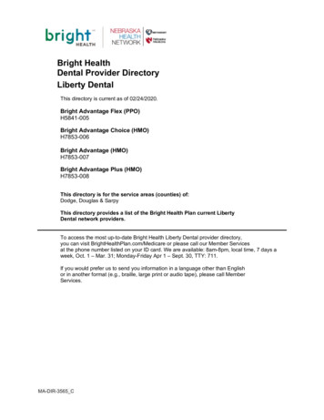
Mandibular fracture – Cone beam CTMandible fracture- Dental radiologyExample of treatment:Alveolar fractureComposite splint/wire stabilizationThe primary method of stabilization in these patients is interdental wiring and compositesplinting as traditional bone plates/external fixator stabilization is associated with traumato tooth roots and vital structures (mandibular canal, nasal cavity). This is minimallyinvasive, patients can eat/drink and function without occlusal interference and this isremoved in 6-8 weeks. Trauma cases that involve the maxilla, mandible and/or the TMJmay require interdental bonding of the canine teeth or elastic chain stabilization of thecanine teeth and esophageal tube feeding strategies. Although titanium locking plates arebeing used for caudal mandibular fractures and some maxillary fractures.Best Dental Radiographic Reference BVookDupont G, Debowes L: Atlas of Dental Radiography in Dogs and Cats, Saunders 200913
Dental Radiograph Interpretation Stephen Juriga DVM, DAVDC . The interpretation of dental radiographs is similar to the systematic approach that we employ with standard radiography in our general practice. This document will review normal and abnormal radiographic anatomy of th