Transcription
Ch 12.qxd5/7/049:54 AMPage 12-1MULTIENGINE FLIGHTGENERALThis chapter is devoted to the factors associated withthe operation of small multiengine airplanes. For thepurpose of this handbook, a “small” multiengine airplane is a reciprocating or turbopropeller-poweredairplane with a maximum certificated takeoff weightof 12,500 pounds or less. This discussion assumes aconventional design with two engines—one mountedon each wing. Reciprocating engines are assumedunless otherwise noted. The term “light-twin,”although not formally defined in the regulations, isused herein as a small multiengine airplane with amaximum certificated takeoff weight of 6,000 poundsor less.The basic difference between operating a multiengineairplane and a single-engine airplane is the potentialproblem involving an engine failure. The penalties forloss of an engine are twofold: performance and control.The most obvious problem is the loss of 50 percentof power, which reduces climb performance 80 to 90percent, sometimes even more. The other is the control problem caused by the remaining thrust, whichis now asymmetrical. Attention to both these factorsis crucial to safe OEI flight. The performance andsystems redundancy of a multiengine airplane is asafety advantage only to a trained and proficientpilot.There are several unique characteristics of multiengineairplanes that make them worthy of a separate class rating. Knowledge of these factors and proficient flightskills are a key to safe flight in these airplanes. Thischapter deals extensively with the numerous aspects ofone engine inoperative (OEI) flight. However, pilotsare strongly cautioned not to place undue emphasison mastery of OEI flight as the sole key to flyingmultiengine airplanes safely. The inoperative engineinformation that follows is extensive only becausethis chapter emphasizes the differences between flyingmultiengine airplanes as contrasted to single-engineairplanes.TERMS AND DEFINITIONSThe modern, well-equipped multiengine airplane canbe remarkably capable under many circumstances. But,as with single-engine airplanes, it must be flown prudently by a current and competent pilot to achieve thehighest possible level of safety.This chapter contains information and guidance on theperformance of certain maneuvers and procedures insmall multiengine airplanes for the purposes of flighttraining and pilot certification testing. The finalauthority on the operation of a particular make andmodel airplane, however, is the airplane manufacturer.Both the flight instructor and the student should beaware that if any of the guidance in this handbook conflicts with the airplane manufacturer’s recommendedprocedures and guidance as contained in the FAAapproved Airplane Flight Manual and/or Pilot’sOperating Handbook (AFM/POH), it is the airplanemanufacturer’s guidance and procedures that takeprecedence.Pilots of single-engine airplanes are already familiarwith many performance “V” speeds and their definitions. Twin-engine airplanes have several additionalV speeds unique to OEI operation. These speeds aredifferentiated by the notation “SE”, for single engine.A review of some key V speeds and several new Vspeeds unique to twin-engine airplanes follows. VR – Rotation speed. The speed at which backpressure is applied to rotate the airplane to a takeoff attitude. VLOF – Lift-off speed. The speed at which theairplane leaves the surface. (Note: some manufacturers reference takeoff performance data toVR, others to VLOF.) VX – Best angle of climb speed. The speed atwhich the airplane will gain the greatest altitudefor a given distance of forward travel. VXSE – Best angle-of-climb speed with oneengine inoperative. VY – Best rate of climb speed. The speed atwhich the airplane will gain the most altitude fora given unit of time. VYSE – Best rate-of-climb speed with one engineinoperative. Marked with a blue radial line onmost airspeed indicators. Above the single-engineabsolute ceiling, VYSE yields the minimum rate ofsink. VSSE – Safe, intentional one-engine-inoperativespeed. Originally known as safe single-engine12-1
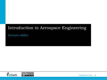
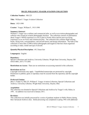
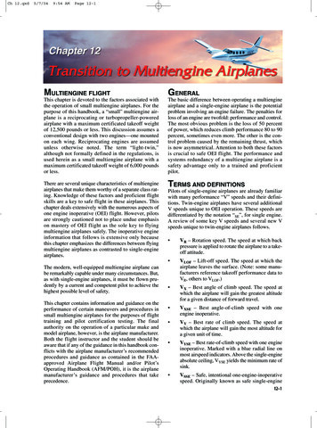
Ch 12.qxd5/7/049:54 AMPage 12-2speed. Now formally defined in Title 14 of theCode of Federal Regulations (14 CFR) part 23,Airworthiness Standards, and required to beestablished and published in the AFM/POH. It isthe minimum speed to intentionally render thecritical engine inoperative. VMC – Minimum control speed with the criticalengine inoperative. Marked with a red radial lineon most airspeed indicators. The minimum speedat which directional control can be maintainedunder a very specific set of circumstances outlinedin 14 CFR part 23, Airworthiness Standards.Under the small airplane certification regulationscurrently in effect, the flight test pilot must be ableto (1) stop the turn that results when the criticalengine is suddenly made inoperative within 20 of the original heading, using maximum rudderdeflection and a maximum of 5 bank, and (2)thereafter, maintain straight flight with notmore than a 5 bank. There is no requirement inthis determination that the airplane be capableof climbing at this airspeed. V MC onlyaddresses directional control. Further discussion of VMC as determined during airplane certification and demonstrated in pilot trainingfollows in minimum control airspeed (V MC)demonstration. [Figure 12-1]Figure 12-1. Airspeed indicator markings for a multiengineairplane.Unless otherwise noted, when V speeds are given inthe AFM/POH, they apply to sea level, standard dayconditions at maximum takeoff weight. Performancespeeds vary with aircraft weight, configuration, andatmospheric conditions. The speeds may be stated instatute miles per hour (m.p.h.) or knots (kts), and theymay be given as calibrated airspeeds (CAS) or indicated airspeeds (IAS). As a general rule, the newer12-2AFM/POHs show V speeds in knots indicated airspeed(KIAS). Some V speeds are also stated in knots calibrated airspeed (KCAS) to meet certain regulatoryrequirements. Whenever available, pilots should operate the airplane from published indicated airspeeds.With regard to climb performance, the multiengineairplane, particularly in the takeoff or landing configuration, may be considered to be a single-engineairplane with its powerplant divided into two units.There is nothing in 14 CFR part 23 that requires amultiengine airplane to maintain altitude while inthe takeoff or landing configuration with one engineinoperative. In fact, many twins are not required todo this in any configuration, even at sea level.The current 14 CFR part 23 single-engine climbperformance requirements for reciprocating enginepowered multiengine airplanes are as follows. More than 6,000 pounds maximum weightand/or VSO more than 61 knots: the singleengine rate of climb in feet per minute (f.p.m.) at5,000 feet MSL must be equal to at least .027VSO2. For airplanes type certificated February 4,1991, or thereafter, the climb requirement isexpressed in terms of a climb gradient, 1.5 percent. The climb gradient is not a direct equivalent of the .027 VSO2 formula. Do not confuse thedate of type certification with the airplane’smodel year. The type certification basis of manymultiengine airplanes dates back to CAR 3 (theCivil Aviation Regulations, forerunner of today’sCode of Federal Regulations). 6,000 pounds or less maximum weight and VSO61 knots or less: the single-engine rate of climbat 5,000 feet MSL must simply be determined.The rate of climb could be a negative number.There is no requirement for a single-enginepositive rate of climb at 5,000 feet or any otheraltitude. For light-twins type certificatedFebruary 4, 1991, or thereafter, the singleengine climb gradient (positive or negative) issimply determined.Rate of climb is the altitude gain per unit of time, whileclimb gradient is the actual measure of altitude gainedper 100 feet of horizontal travel, expressed as a percentage. An altitude gain of 1.5 feet per 100 feet oftravel (or 15 feet per 1,000, or 150 feet per 10,000) is aclimb gradient of 1.5 percent.There is a dramatic performance loss associated withthe loss of an engine, particularly just after takeoff.Any airplane’s climb performance is a function ofthrust horsepower which is in excess of that required
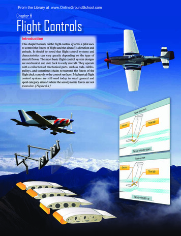
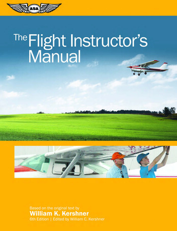
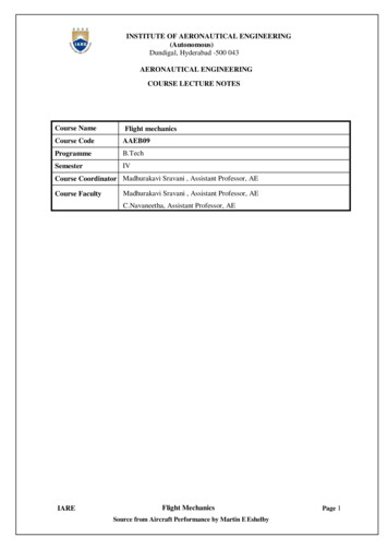
Ch 12.qxd5/7/049:54 AMPage 12-3for level flight. In a hypothetical twin with each engineproducing 200 thrust horsepower, assume that the totallevel-flight thrust horsepower required is 175. In thissituation, the airplane would ordinarily have a reserveof 225 thrust horsepower available for climb. Loss ofone engine would leave only 25 (200 minus 175) thrusthorsepower available for climb, a drastic reduction.Sea level rate-of-climb performance losses of at least80 to 90 percent, even under ideal circumstances, aretypical for multiengine airplanes in OEI flight.OPERATION OF SYSTEMSThis section will deal with systems that are generallyfound on multiengine airplanes. Multiengine airplanesshare many features with complex single-engine airplanes. There are certain systems and features coveredhere, however, that are generally unique to airplaneswith two or more engines.PROPELLERSThe propellers of the multiengine airplane may outwardly appear to be identical in operation to theconstant-speed propellers of many single-engineairplanes, but this is not the case. The propellers ofmultiengine airplanes are featherable, to minimizedrag in the event of an engine failure. Dependingupon single-engine performance, this feature oftenpermits continued flight to a suitable airport followingan engine failure. To feather a propeller is to stopengine rotation with the propeller blades streamlinedwith the airplane’s relative wind, thus to minimizedrag. [Figure 12-2]Feathering is necessary because of the change in parasite drag with propeller blade angle. [Figure 12-3]When the propeller blade angle is in the featheredposition, the change in parasite drag is at a minimumand, in the case of a typical multiengine airplane, theadded parasite drag from a single feathered propelleris a relatively small contribution to the airplane totaldrag.At the smaller blade angles near the flat pitch position,the drag added by the propeller is very large. At thesesmall blade angles, the propeller windmilling at highr.p.m. can create such a tremendous amount of drag thatthe airplane may be uncontrollable. The propeller windmilling at high speed in the low range of blade anglescan produce an increase in parasite drag which may beas great as the parasite drag of the basic airplane.As a review, the constant-speed propellers on almostall single-engine airplanes are of the non-feathering,oil-pressure-to-increase-pitch design. In this design,increased oil pressure from the propeller governordrives the blade angle towards high pitch, low r.p.m.In contrast, the constant-speed propellers installedon most multiengine airplanes are full feathering,LowPitchFullFeathered90 HighPitchFigure 12-2. Feathered propeller.counterweighted, oil-pressure-to-decrease-pitchdesigns. In this design, increased oil pressure from thepropeller governor drives the blade angle towards lowpitch, high r.p.m.—away from the feather blade angle.In effect, the only thing that keeps these propellersfrom feathering is a constant supply of high pressureengine oil. This is a necessity to enable propeller feathering in the event of a loss of oil pressure or a propellergovernor failure.PROPELLER DRAG CONTRIBUTIONWindmillingPropellerChange edPositionFlat Blade Position015304560Propeller Blade Angle90Figure 12-3. Propeller drag contribution.12-3
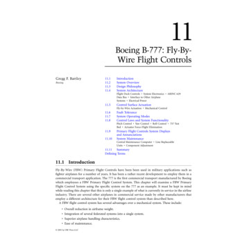
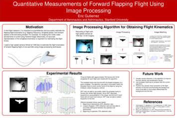
Ch 12.qxd5/7/049:54 AMPage 12-4The aerodynamic forces alone acting upon a windmilling propeller tend to drive the blades to low pitch,high r.p.m. Counterweights attached to the shank ofeach blade tend to drive the blades to high pitch, lowr.p.m. Inertia, or apparent force called centrifugal forceacting through the counterweights is generally slightlygreater than the aerodynamic forces. Oil pressure fromthe propeller governor is used to counteract the counterweights and drives the blade angles to low pitch,high r.p.m. A reduction in oil pressure causes the r.p.m.to be reduced from the influence of the counterweights.[Figure 12-4]To feather the propeller, the propeller control isbrought fully aft. All oil pressure is dumped from thegovernor, and the counterweights drive the propellerblades towards feather. As centrifugal force acting onthe counterweights decays from decreasing r.p.m.,additional forces are needed to completely feather theblades. This additional force comes from either aspring or high pressure air stored in the propellerdome, which forces the blades into the feathered position. The entire process may take up to 10 seconds.Feathering a propeller only alters blade angle and stopsengine rotation. To completely secure the engine, thepilot must still turn off the fuel (mixture, electric boostpump, and fuel selector), ignition, alternator/generator,and close the cowl flaps. If the airplane is pressurized,there may also be an air bleed to close for the failedengine. Some airplanes are equipped with firewallshutoff valves that secure several of these systemswith a single switch.Completely securing a failed engine may not be necessary or even desirable depending upon the failuremode, altitude, and time available. The position of thefuel controls, ignition, and alternator/generatorswitches of the failed engine has no effect on aircraftperformance. There is always the distinct possibilityof manipulating the incorrect switch under conditionsof haste or pressure.To unfeather a propeller, the engine must be rotatedso that oil pressure can be generated to move thepropeller blades from the feathered position. Theignition is turned on prior to engine rotation with thethrottle at low idle and the mixture rich. With thepropeller control in a high r.p.m. position, the starteris engaged. The engine will begin to windmill, start,and run as oil pressure moves the blades out offeather. As the engine starts, the propeller r.p.m.should be immediately reduced until the engine hashad several minutes to warm up; the pilot shouldmonitor cylinder head and oil temperatures.Should the r.p.m. obtained with the starter be insufficient to unfeather the propeller, an increase in airspeedCounterweightActionHydraulic ForceAerodynamic ForceNitrogen Pressure or SpringForce, and Counterweight ActionHigh-pressure oil enters the cylinder through the center ofthe propeller shaft and piston rod. The propeller controlregulates the flow of high-pressure oil from a governor.The forks push the pitch-change pin of each bladetoward the front of the hub, causing the blades to twisttoward the low-pitch position.A hydraulic piston in the hub of the propeller is connectedto each blade by a piston rod. This rod is attached to forksthat slide over the pitch-change pin mounted in the root ofeach blade.A nitrogen pressure charge or mechanical spring inthe front of the hub opposes the oil pressure, andcauses the propeller to move toward high-pitch.The oil pressure moves the piston toward the front of thecylinder, moving the piston rod and forks forward.Counterweights also cause the blades to move towardthe high-pitch and feather positions. The counterweights counteract the aerodynamic twisting force thattries to move the blades toward a low-pitch angle.Figure 12-4. Pitch change forces.12-4
Ch 12.qxd5/7/049:54 AMPage 12-5from a shallow dive will usually help. In any event, theAFM/POH procedures should be followed for theexact unfeathering procedure. Both feathering andstarting a feathered reciprocating engine on the groundare strongly discouraged by manufacturers due to theexcessive stress and vibrations generated.As just described, a loss of oil pressure from the propeller governor allows the counterweights, springand/or dome charge to drive the blades to feather.Logically then, the propeller blades should featherevery time an engine is shut down as oil pressure fallsto zero. Yet, this does not occur. Preventing this is asmall pin in the pitch changing mechanism of thepropeller hub that will not allow the propeller bladesto feather once r.p.m. drops below approximately800. The pin senses a lack of centrifugal force frompropeller rotation and falls into place, preventing theblades from feathering. Therefore, if a propeller is tobe feathered, it must be done before engine r.p.m.decays below approximately 800. On one popularmodel of turboprop engine, the propeller blades do,in fact, feather with each shutdown. This propeller isnot equipped with such centrifugally-operated pins,due to a unique engine design.An unfeathering accumulator is an optional device thatpermits starting a feathered engine in flight without theuse of the electric starter. An accumulator is any devicethat stores a reserve of high pressure. On multiengineairplanes, the unfeathering accumulator stores a smallreserve of engine oil under pressure from compressedair or nitrogen. To start a feathered engine in flight,the pilot moves the propeller control out of thefeather position to release the accumulator pressure.The oil flows under pressure to the propeller hub anddrives the blades toward the high r.p.m., low pitchposition, whereupon the propeller will usually beginto windmill. (On some airplanes, an assist from theelectric starter may be necessary to initiate rotationand completely unfeather the propeller.) If fuel andignition are present, the engine will start and run.For airplanes used in training, this saves much electric starter and battery wear. High oil pressure fromthe propeller governor recharges the accumulatorjust moments after engine rotation begins.PROPELLER SYNCHRONIZATIONMany multiengine airplanes have a propeller synchronizer (prop sync) installed to eliminate the annoying“drumming” or “beat” of propellers whose r.p.m. areclose, but not precisely the same. To use prop sync, thepropeller r.p.m. are coarsely matched by the pilot andthe system is engaged. The prop sync adjusts the r.p.m.of the “slave” engine to precisely match the r.p.m. ofthe “master” engine, and then maintains that relationship. The prop sync should be disengaged when thepilot selects a new propeller r.p.m., then re-engagedafter the new r.p.m. is set. The prop sync should alwaysbe off for takeoff, landing, and single-engine operation. The AFM/POH should be consulted for systemdescription and limitations.A variation on the propeller synchronizer is the propeller synchrophaser. Prop sychrophase acts muchlike a synchronizer to precisely match r.p.m., but thesynchrophaser goes one step further. It not onlymatches r.p.m. but actually compares and adjusts thepositions of the individual blades of the propellers intheir arcs. There can be significant propeller noise andvibration reductions with a propeller synchrophaser.From the pilot’s perspective, operation of a propellersynchronizer and a propeller syncrophaser are verysimilar. A synchrophaser is also commonly referred toas prop sync, although that is not entirely correctnomenclature from a technical standpoint.As a pilot aid to manually synchronizing thepropellers, some twins have a small gauge mountedin or by the tachometer(s) with a propeller symbolon a disk that spins. The pilot manually fine tunesthe engine r.p.m. so as to stop disk rotation, therebysynchronizing the propellers. This is a useful backupto synchronizing engine r.p.m. using the audiblepropeller beat. This gauge is also found installedwith most propeller synchronizer and synchrophasesystems. Some synchrophase systems use a knob forthe pilot to control the phase angle.FUEL CROSSFEEDFuel crossfeed systems are also unique to multiengineairplanes. Using crossfeed, an engine can draw fuelfrom a fuel tank located in the opposite wing.On most multiengine airplanes, operation in the crossfeed mode is an emergency procedure used to extendairplane range and endurance in OEI flight. There area few models that permit crossfeed as a normal, fuelbalancing technique in normal operation, but these arenot common. The AFM/POH will describe crossfeedlimitations and procedures, which vary significantlyamong multiengine airplanes.Checking crossfeed operation on the ground with aquick repositioning of the fuel selectors does nothingmore than ensure freedom of motion of the handle. Toactually check crossfeed operation, a complete, functional crossfeed system check should be accomplished.To do this, each engine should be operated from itscrossfeed position during the runup. The enginesshould be checked individually, and allowed to run atmoderate power (1,500 r.p.m. minimum) for at least 1minute to ensure that fuel flow can be established fromthe crossfeed source. Upon completion of the check,each engine should be operated for at least 1 minute atmoderate power from the main (takeoff) fuel tanks toreconfirm fuel flow prior to takeoff.12-5
Ch 12.qxd5/7/049:54 AMPage 12-6This suggested check is not required prior to everyflight. Infrequently used, however, crossfeed lines areideal places for water and debris to accumulate unlessthey are used from time to time and drained using theirexternal drains during preflight. Crossfeed is ordinarily not used for completing single-engine flights whenan alternate airport is readily at hand, and it is neverused during takeoff or landings.COMBUSTION HEATERCombustion heaters are common on multiengineairplanes. A combustion heater is best described asa small furnace that burns gasoline to produceheated air for occupant comfort and windshielddefogging. Most are thermostatically operated, andhave a separate hour meter to record time in servicefor maintenance purposes. Automatic overtemperatureprotection is provided by a thermal switch mounted onthe unit, which cannot be accessed in flight. Thisrequires the pilot or mechanic to actually visuallyinspect the unit for possible heat damage in order toreset the switch.When finished with the combustion heater, a cooldown period is required. Most heaters require that outside air be permitted to circulate through the unit for atleast 15 seconds in flight, or that the ventilation fan beoperated for at least 2 minutes on the ground. Failureto provide an adequate cool down will usually trip thethermal switch and render the heater inoperative untilthe switch is reset.FLIGHT DIRECTOR/AUTOPILOTFlight director/autopilot (FD/AP) systems are commonon the better-equipped multiengine airplanes. Thesystem integrates pitch, roll, heading, altitude, andradio navigation signals in a computer. The outputs,called computed commands, are displayed on a flightcommand indicator, or FCI. The FCI replaces theconventional attitude indicator on the instrumentpanel. The FCI is occasionally referred to as a flightdirector indicator (FDI), or as an attitude directorindicator (ADI). The entire flight director/autopilotsystem is sometimes called an integrated flight control system (IFCS) by some manufacturers. Othersmay use the term “automatic flight control system(AFCS).”The FD/AP system may be employed at three differentlevels. Off (raw data). Flight director (computed commands). Autopilot.With the system off, the FCI operates as an ordinaryattitude indicator. On most FCIs, the command barsare biased out of view when the flight director is off.12-6The pilot maneuvers the airplane as though the systemwere not installed.To maneuver the airplane using the flight director, thepilot enters the desired modes of operation (heading,altitude, nav intercept, and tracking) on the FD/APmode controller. The computed flight commands arethen displayed to the pilot through either a single-cueor dual-cue system in the FCI. On a single-cue system,the commands are indicated by “V” bars. On adual-cue system, the commands are displayed ontwo separate command bars, one for pitch and onefor roll. To maneuver the airplane using computedcommands, the pilot “flies” the symbolic airplaneof the FCI to match the steering cues presented.On most systems, to engage the autopilot the flightdirector must first be operating. At any time thereafter,the pilot may engage the autopilot through the modecontroller. The autopilot then maneuvers the airplaneto satisfy the computed commands of the flightdirector.Like any computer, the FD/AP system will only dowhat it is told. The pilot must ensure that it has beenproperly programmed for the particular phase of flightdesired. The armed and/or engaged modes are usuallydisplayed on the mode controller or separate annunciator lights. When the airplane is being hand-flown, ifthe flight director is not being used at any particularmoment, it should be off so that the command bars arepulled from view.Prior to system engagement, all FD/AP computer andtrim checks should be accomplished. Many newersystems cannot be engaged without the completion ofa self-test. The pilot must also be very familiar withvarious methods of disengagement, both normal andemergency. System details, including approvals andlimitations, can be found in the supplements sectionof the AFM/POH. Additionally, many avionics manufacturers can provide informative pilot operatingguides upon request.YAW DAMPERThe yaw damper is a servo that moves the rudder inresponse to inputs from a gyroscope or accelerometerthat detects yaw rate. The yaw damper minimizesmotion about the vertical axis caused by turbulence.(Yaw dampers on sweptwing airplanes provideanother, more vital function of damping dutch rollcharacteristics.) Occupants will feel a smoother ride,particularly if seated in the rear of the airplane, whenthe yaw damper is engaged. The yaw damper shouldbe off for takeoff and landing. There may be additionalrestrictions against its use during single-engine operation. Most yaw dampers can be engaged independentlyof the autopilot.
Ch 12.qxd5/7/049:54 AMPage 12-7ALTERNATOR/GENERATORAlternator or generator paralleling circuitry matchesthe output of each engine’s alternator/generator so thatthe electrical system load is shared equally betweenthem. In the event of an alternator/generator failure,the inoperative unit can be isolated and the entireelectrical system powered from the remaining one.Depending upon the electrical capacity of the alternator/generator, the pilot may need to reduce theelectrical load (referred to as load shedding) whenoperating on a single unit. The AFM/POH will containsystem description and limitations.Anti-icing equipment is provided to prevent ice fromforming on certain protected surfaces. Anti-icingequipment includes heated pitot tubes, heated or nonicing static ports and fuel vents, propeller blades withelectrothermal boots or alcohol slingers, windshieldswith alcohol spray or electrical resistance heating,windshield defoggers, and heated stall warning liftdetectors. On many turboprop engines, the “lip”surrounding the air intake is heated either electricallyor with bleed air. In the absence of AFM/POH guidanceto the contrary, anti-icing equipment is actuated prior toflight into known or suspected icing conditions.NOSE BAGGAGE COMPARTMENTNose baggage compartments are common on multiengineairplanes (and are even found on a few single-engineairplanes). There is nothing strange or exotic about anose baggage compartment, and the usual guidanceconcerning observation of load limits applies. Theyare mentioned here in that pilots occasionally neglectto secure the latches properly, and therein lies thedanger. When improperly secured, the door will openand the contents may be drawn out, usually into thepropeller arc, and usually just after takeoff. Even whenthe nose baggage compartment is empty, airplaneshave been lost when the pilot became distracted by theopen door. Security of the nose baggage compartmentlatches and locks is a vital preflight item.Deicing equipment is generally limited to pneumaticboots on wing and tail leading edges. Deicing equipment is installed to remove ice that has already formedon protected surfaces. Upon pilot actuation, the bootsinflate with air from the pneumatic pumps to break offaccumulated ice. After a few seconds of inflation, theyare deflated back to their normal position with theassistance of a vacuum. The pilot monitors the buildupof ice and cycles the boots as directed in theAFM/POH. An ice light on the left engine nacelleallows the pilot to monitor wing ice accumulation atnight.Most airplanes will continue to fly with a nose baggage door open. There may be some buffeting fromthe disturbed airflow and there will be an increase innoise. Pilots should never become so preoccupiedwith an open door (of any kind) that they fail to flythe airplane.Inspection of the compartment interior is also animportant preflight item. More than one pilot has beensurprised to find a supposedly empty compartmentpacked to capacity or loaded with ballast. The towbars, engine inlet covers, windshield sun screens, oilcontainers, spare chocks, and miscellaneous smallhand tools that find their way into baggage compartments should be secured to prevent damage fromshifting in flight.ANTI-ICING/DEICINGAnti-icing/deicing equipment is frequently installed onmultiengine airplanes and consists of a combination ofdifferent systems. These may be classified as eitheranti-icing or deicing, depending upon function. Thepresence of anti-icing and deicing equipment, eventhough it may appear elaborate and complete, does notnecessarily mean that the airplane is approved forflight in icing conditions. The AFM/POH, placards,and even the manufacturer should be consulted forspecific determination of approvals and limitations.Other airframe equipment necessary for flight in icingconditions includes an alternate induction air sourceand an alternate static system source. Ice tolerantantennas will also be installed.In the event of impact ice accumulating over normalengine air induction sources, carburetor heat (carbureted engines) or alternate air (fuel injected engines)should be selected. Ice buildup on normal inductionsources can
approved Airplane Flight Manual and/or Pilot’s Operating Handbook (AFM/POH), it is the airplane manufacturer’s guidance and procedures that take precedence. GENERAL The basic difference between operating a multiengine airplane and a single-engine airplane is the potenti