Transcription
Version Date: 3-3-2010 2008-2010 - Brett Miller and Muhammad Iqbal.All rights reserved. License granted for non-commercial use only.BUILD YOUR OWN DS-1 DISTORTIONCREDITSDocument Author: Brett “5thumbs” Miller, five.thumbs@yahoo.comNotable Technical Contributor: Muhammad “miqbal” Iqbal, iqbal.tiro@gmail.comSpecial thanks to the following who helped make this document possible:1) Johan and everyone else at the freestompboxes.org forum.2) Jack Orman for his “More Saturation Controls” article, his DS-1 Q2 gain mod, along with all the information he’s shared with the DIY pedal community.3) Mark Hammer for his assistance with the ‘True-Bypass DS-1 Distortion’ circuit, plus all the experience and guidance he’s shared with us DIYers.4) R.G. Keen for generously sharing his vast knowledge and patience with us all.5) Robert Keeley for making information on his DS-1 “Seeing Eye” and “Ultra” mods available to the public.6) Mxrmxr and Christ Briere (cbriere) at freestompboxes.org for schematic information for the Tonebone ClassicTM and JMP-1TM preamp.7) The folks at Bossarea.com for information assisting in identifying power components in the pre-1994 DS-1 pedals.8) Aron Nelson and everyone else at the diystompboxes.com forum.DISCLAIMERThe information in this document is accurate to the best of the authors’ knowledge. While we’ve done our best to get all the details correct, there are nowarranties or guarantees express or implied regarding its accuracy. This information is provided for reference purposes only, which essentially means that if youblow up your DS-1 while modifying it, burn yourself on a soldering iron while trying to build a pedal based upon these instructions or fall victim to some othermisfortune after reading this information it’s your fault, not ours.If you are having issues with your DS-1 mod or replica build, please visit the forums at freestompboxes.org or diystompboxes.com and use the Search feature tosee if your problem has been previously solved by others. If not, please use this format when posting for help in either forum. By doing this, you may solve theproblem yourself before posting and if not, you’ll be communicating in a manner that will allow the other members of the forum to help you more readily.All trademarks remain the property of their respective owners. (Tonebone ClassicTM is a trademarked product of Radial EngineeringTM. JMP-1TM is a trademarked product of Marshall Amplification plc. BOSS is a registered trademark of the Roland Corporation.) None of the information represented in this document isaffiliated with or endorsed by these entities.CONTENTS1. Introduction8. Brett Miller DS-1 “Vintage Ripper” Mod2. Build a Stock DS-1 Distortion9. Brett Miller DS-1 “Huevos Grandes” Mod3. Build a True-Bypass DS-1 Distortion10. Sound Clips4. Robert Keeley DS-1 “Seeing Eye” / “Ultra” Mods11. Appendix A: Where Can I Find B20K Pots?5. Brett Miller DS-1 “MIJ” Mod12. Appendix B: How Do I Modify My Post-1994 DS-1 To Match The Original DS-1?6. Brett Miller DS-1 “Mondo-MIJ” Mod7. Brett Miller DS-1 “PHLAT” Mod1
INTRODUCTIONHave you ever wanted to build your own DS-1 Distortion, but could only find work-a-likes, schematics for the pre-1994 “vintage” DS-1 or just plain inaccurateschematics on the Internet? If so, then this document is for you. We’ll give you the information you need to build a version of the DS-1 distortion that matchesthe exact circuit used by the large Japanese manufacturer of the original post-1994 DS-1 Distortion (with the exception of replacing the SIP-8 dual op amp layoutwith a DIP-8 dual op amp layout.)Please be advised that both of the DS-1 layouts in this document are a bit more complicated than your average beginner-level project. Please consider thefollowing factors and honestly assess your skill-level before you begin building this project:1. The component count is higher than a booster/overdrive/simple distortion (like the MXR Distortion ), which means more places to have to troubleshoot in the event of a failure.2. The component spacing is rather tight on both layouts, so you will need to solder with care to avoid creating short-circuits via solder bridges.3. If you attempt to build the “Stock DS-1 Distortion”, you will be working with JFETs in the flip-flop switching circuitry. Multiple JFETs often need to betested and grouped to get a set of individual JFETs that will work as desired in the circuit. The topic of JFET matching is beyond the scope of thisdocument, but if you wish to learn more about this topic, please read more about it over at GEOFEX.Given these factors, I’d rate the difficulty of this project as INTERMEDIATE. This means it is probably not a good idea for your first pedal build, but it will not beoverly-difficult if you take your time and carefully assemble the pedal with the knowledge and skills you’ve developed in your previous pedal buildingexperience.2
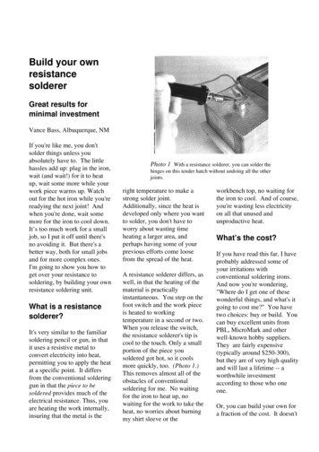
BUILD A STOCK DS-1 DISTORTIONThis schematic was reverse-engineered by Muhammad Iqbal from images of actual DS-1 circuit boards. All components in the schematic below are labeled withthe same labels as the commercially-produced product, so if you find new DS-1 mods on the Internet that reference component numbers on the commerciallyproduced DS-1, they will be applicable to this circuit as well. This schematic includes all of the components from the original DS-1 board, including input andoutput buffers, as well as the switching circuitry.This layout has been built and verified as successful by Muhammad Iqbal.3
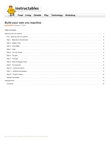
The layout below is designed to fit into a BOSS -style pedal enclosure, but may also be fit into a 1790-style enclosure.Component Layout (enlarged):Ready-To-Transfer:Stock DS-1 Layouts by: Muhammad Iqbal4
Stock DS-1 Connections:W1W2, W3, W4 (VR1)W5, W6, W7 (VR2)W8, W9, W10 (VR3)W11W12– Input– DIST Control, 100KΩ Linear Potentiometer– LEVEL Control, 100KΩ Linear Potentiometer– TONE Control, 20KΩ Linear Potentiometer– Output– Ground to Input SleeveW13W14W15W16W17W18– Effect Switch, SPST Momentary– Board to Input Jack Ring, then Battery Negative (-)– 9V to LED ( )– Battery Positive ( )– Effect Switch, SPST Momentary– Power return from LED Negative (-) to flip-flop switching circuitStock DS-1 Parts List:C1 – 0.047μFC2 – 0.47μF/50VC3 – 0.047μFC4 – 250pFC5 – 0.068μFC6 – omitted in originalC7 – 100pFC8 – 1μF/50VC9 – 0.47μF/50V NPC10 – 0.01μFC11 – 0.022uFC12 – 0.1μFC13 – 0.047μFC14 – 1μF/50VC15 – 47μF/6.3VC16 – 470pFC17 – 470pFC18 – 220pFC19 – 220pFC20 – 0.047μFC21 – 0.047μFC22 – 0.01μFC23 – 100μF/16VR1 – 1KΩR2 – 470KΩR3 – 10KΩR4 – 100KΩR5 – 1MΩR6 – 100KΩR7 – 470KΩR8 – 10KΩR9 – 22ΩR10 – 100KΩR11 – 100KΩR12 – omitted in originalR13 – 4K7ΩR14 – 2K2ΩR15 – 2K2ΩR16 – 6K8ΩR17 – 6K8ΩR18 – 10KΩR19 – 1MΩR20 – 1MΩR21 – 10KΩR22 – 1KΩR23 – 100KΩR24 – 10KΩR25 – 10KΩR26 – 100KΩR27 – 100KΩR28 – 56KΩR29 – 56KΩR30 – 56KΩR31 – 56KΩR32 – 1MΩR33 – 1MΩR34 – omitted in originalR35 – 3K9ΩR36 – 1MΩR37 – 100ΩR38 – omitted in originalR39 – 47KΩR40 – 1KΩD1 – 1N4004D2 – 5.6V ZenerD3 – omitted in originalD4 – 1N4150D5 – 1N4150D6 – 1N4148D7 – 1N4148D8 – 1N41485Q1 – 2SC2240*Q2 – 2SC2240Q3 – 2SC2240Q4 – 2SC2458**Q5 – 2SC2458Q6 – 2SK30A***Q7 – 2SK30AQ8 – 2SK30ALED1 – 3mm Red LEDSW1 – SPST momentaryVR1 – 100KΩ Linear PotVR2 – 100KΩ Linear PotVR3 – 20KΩ Linear PotIC1 – NJM3404ADNOTE:The NJM3404AL SIP8 dual opamp is currently used in post1994 DS-1 pedals. This chip isavailable in DIP-8 format, butthe older M5223AL andBA728N dual op amps are not.If you’re going for a stock DS1, try the NJM3404AD (DIP-8)in this layout.*2N5088 transistors may beused in place of 2SC2240transistors. You will need toorient the pins differently, asthe 2SC2240 are B-C-E and2N5088 are C-B-E.** BC549 or BC559 transistorsmay be used in place of2SC2458 transistors. You willneed to orient the pinsdifferently, as the 2SC2458 areB-C-E and BC549/BC559 are CB-E.***2N5457 transistors aresomewhat close to 2SK30Atransistors. You will need toorient the pins differently, asthe 2SK30A are S-G-D and2N5457 are G-S-D. If you wantto purchase 2SK30Atransistors, Small BearElectronics has them.
Stock DS-1 Wiring:The diagram below is a 1:1 scale image of an installation of the Stock DS-1 in a 1790-style enclosure.1:16
Stock DS-1 Enclosure Drilling Template:Print out this page, cut out the diagram below and place it on top of your 1790-style enclosure, folding the smaller rounded rectangle over the edge and tapeeverything down securely. All holes are sized according to manufacturer specifications. Since there are variances between hole sizes required by differentmanufacturers, you may need to reduce/enlarge some of the holes to fit your components. It is a good practice to purchase a dial caliper and measure the exactparts you plan to use before drilling any enclosure, but this template should work for most components available.7
BUILD A TRUE-BYPASS DS-1 DISTORTION This schematic was developed by Brett Miller from Muhammad Iqbal’s “BOSS DS-1 Distortion” schematic. All components in the schematic below are labeledwith the same labels as the commercially-produced product, so if you find new DS-1 mods on the Internet that reference component numbers on thecommercially-produced DS-1, they will be applicable to this circuit as well. This schematic does not include all of the components from the original DS-1 board,as it removes the input/output buffers and the switching circuitry.This schematic also includes Robert Keeley’s “Seeing Eye” and “Ultra” mods, which are described in-depth in the “Robert Keeley DS-1 “Seeing Eye” / “Ultra”Mods” section at the end of this document. Please note that circuit components that map to the original DS-1 circuit have red lines, whereas the Keeley modshave orange lines. You can build this design with or without the Keeley mods, but if you do not include the mods, please be sure to install jumpers between thepads marked ‘COM’ and ’1’ on the SPDT1 and SPDT2, as indicated on the Component Layout. I would recommend installing the Keeley mods, as I have designedit to allow switching between either Keeley diode mod individually, or you can switch the clipping diode mods off altogether and have a nearly-stock DS-1 sound.This layout is unverified at this time, as I’ve got six DS-1 pedals of various vintages and mods and I really don’t want or need a true-bypass model. If you buildthis successfully, please let me know and I’ll credit you as the initial build verifier in this doc.8
The layout below is designed to fit into a Hammond 1590BB-style er:True-Bypass DS-1 Layouts by: Brett Miller9
True-Bypass DS-1 Connections:INW2, W3, W4 (VR1)W5, W6, W7 (VR2)W8, W9, W10 (VR3)– Input– DIST Control, 100KΩ Linear Potentiometer– LEVEL Control, 100KΩ Linear Potentiometer– TONE Control, 20KΩ Linear PotentiometerOUTGND 9VLED – Output– Ground– 9V Input– Current-limited 9V power to status LED (LED1)True-Bypass DS-1 Parts List:C3 – 47nFC4 – 250pFC5 – 68nFC7 – 100pFC8 – 0.47μFC9 – 0.47μFC10 – 10nFC11 – 22nFC12 – 100nFC14 – 1μF/50VC15 – 47μF/6.3VC16 – 470pFC23 – 100μF/16VMC1 – 47pFR5 – 1MΩR6 – 100KΩR7 – 470KΩR8 – 10KΩR9 – 22ΩR10 – 100KΩR11 – 100KΩR13 – 4K7ΩR14 – 2K2ΩR15 – 2K2ΩR16 – 6K8ΩR17 – 6K8ΩR18 – omitted in TB layoutR23 – 100KΩR24 – 10KΩR25 – 10KΩR39 – 47KΩR40 – 1KΩLR1 – 4K7ΩD1 – 1N4004D4 – 1N4150D5 – 1N4150D8 – 1N4148Q2 – 2N5088*VR1 – 100KΩ Linear PotVR2 – 100KΩ Linear PotVR3 – 20KΩ Linear PotLED1 – 3mm Red LEDIC1 – NJM3404ADMD1 – 1N4148MLED1 – 3mm Red LEDMLED2 – 3mm Red LEDSW1 – 3PDT latchingSPDT1 – SPDT toggle, ON-ONSPDT2 – SPDT toggle, ON-ON10NOTE:The NJM3404AL SIP8 dual opamp is currently used in post1994 DS-1 pedals. This chip isavailable in DIP-8 format, butthe older M5223AL andBA728N dual op amps arenot. If you’re going for astock DS-1, try theNJM3404AD (DIP-8) in thislayout.*2SC2240 transistors may beused in place of 2N5088transistors. I have designedthis layout around the2N5088, so if you want to use2SC2240 as in the original,you will need to orient thepins differently, as the2SC2240 are B-C-E and2N5088 areC-B-E.
True-Bypass DS-1 Wiring:The diagram below is a 1:1 scale image of an installation of the True-Bypass DS-1 in a Hammond 1590BB-style enclosure.1:111
True-Bypass DS-1 Enclosure Drilling Template:Print out this page, cut out the diagram below and place it on top of your Hammond 1590BB enclosure, folding the smaller rounded rectangle over the edge andtape everything down securely. All holes are sized according to manufacturer specifications. Since there are variances between hole sizes required by differentmanufacturers, you may need to reduce/enlarge some of the holes to fit your components. It is a good practice to purchase a dial caliper and measure the exactparts you plan to use before drilling any enclosure, but this template should work for most components available.12
ROBERT KEELEY DS-1 “SEEING EYE” / “ULTRA” MODSRobert Keeley has public information on his site about his DS-1 “Seeing Eye” and “Ultra” mods here: http://www.robertkeeley.com/audio6l6/dstech.html, whichis why his mod information is included in this document.There are other modifications you can make to your DS-1 that are too numerous to list here. Please visit the freestompboxes.org forum or diystompboxes.comforum and search for “DS-1 mods” to find more mods for your DS-1.Robert Keeley’s DS-1 “Seeing Eye” / “Ultra” Mod:1)2)3)4)5)6)7)8)Replace C1, C3, C5, C12 and C13 with 0.1μF metal film capacitors.Replace C2, C8, C9 and C14 with 1μF metal film capacitors.Replace C11 with 0.047μF metal film capacitor.Replace C7 with a 220pF silver mica capacitor.Replace R13 with a 2.4KΩ metal film resistor.Replace R39 with a 20KΩ metal film resistor.Replace R14 with a 1.5KΩ metal film resistor.Add a 47pF silver mica capacitor in parallel to the D4/D5 clipping diodes (as illustrated below.)This mod is soldered on the trace-side of the board, not on the component-side.NOTE: On the “True-Bypass DS-1 Distortion” build instructions above, you do not need to solder the 47pF cap across the D4/D5 diodes as illustratedimmediately above, as I have added holes/pads to the left of D4/D5 for you to add this cap as part of the “Ultra” mod.13
9) “ULTRA” Diode Mod:Add a 3mm red LED in series with D4. To make this mod switchable so you can choose to have the LED/D4 diode combination or just the D4 diode, youcan wire an On-On SPDT toggle switch as follows:You will need one additional 1N4148 (or other diode matching the one in D4) to construct this mod as illustrated below.NOTE: On the “True-Bypass DS-1 Distortion” build instructions above, you do not need to remove D4 and off-board wire the switch with diodes/LED asillustrated immediately above, as I have added holes/pads near D4/D5 for you to add the SPDT switch and LED as part of the “Ultra” mod.14
10) “Seeing Eye” Diode Mod:Replace D5 with a 3mm red LED. To make this mod switchable so you can choose to have the LED or just the D5 diode, you can wire an On-On SPDTtoggle switch as follows:You may use the original D5 diode as illustrated below.NOTE: On the “True-Bypass DS-1 Distortion” build instructions above, you do not need to remove D5 and off-board wire the switch with diode/LED asillustrated immediately above, as I have added holes/pads near D4/D5 for you to add the SPDT switch and LED as part of the “Seeing Eye” mod.15
BRETT MILLER DS-1 “MIJ” MODIn Appendix B, I describe the major differences between the vintage, pre-1994 DS-1 and the post-1994 pedal. If you would like to understand why thecomponents in the MIJ-Mod were selected and changed to the values below, please read that section.The intent of this mod is to alter the post-1994 DS-1 to make it sound like the vintage DS-1. I’ve tested a stock DS-1 modified with the MIJ-Mod side-by-side witha genuine pre-1994, MIJ DS-1 and found the similarity in sound characteristics to be remarkable.NOTE: This mod represents the coalescence of both the previous “MIJ Mod” and “MIJ Plus” mods. These mods previously existed separately because I wasunaware the D4/D5 clipping diodes in the M.I.J. DS-1 (1S2473 diodes) clipped near 1V, not 0.65V as with diodes used in the post-1994 DS-1; the two previousmods differed only in their clipping diodes. This revelation in itself explains a large part of the mystery of why the M.I.J. DS-1 pedal sounds better than the post1994 DS-1 pedal. It also removes the need to have two separate mods. If you previously installed either the “old” MIJ Mod or MIJ-Plus Mod and want to updateit to the latest MIJ Mod, simply skip to Step #4 below.Please also bear the difference in clipping diodes in mind as you listen to the MIJ Mod and MIJ-Plus Mod sound clips. The sound clips labeled “MIJ Mod” havestock, post-1994 diodes that clip around 0.65V, whereas the sound clips labeled “MIJ-Plus Mod” will have a clipping sound very similar to this “updated” MIJMod with 0.9-1V clipping diodes.Mod Steps:1. Change C7 from 100pF ceramic disc capacitor to a 250pF ceramic disc capacitor.2. Change C8 from 0.47μF/50V aluminum electrolytic capacitor to 1uF/50V aluminum electrolytic capacitor; save the 0.47μF/50V cap for the next step.3. Remove the 0.068μF film capacitor from C5 and replace it with the 0.47μF/50V aluminum electrolytic capacitor previously removed from C8 in Step 2.4. Replace D4 and D5 with diodes (or anything else you can make work) that clip with a forward voltage (VF) around 0.9-1.0V.(NEW! Step Added 1/28/2010.)NOTE: The 1S2473 diodes used in the original MIJ DS-1 had a VF of 0.92 to 1.0 volts. This is much higher than the 0.65 volts VF of the 1N4148-type diodesused in the MIT post-1994 DS-1. A few easy ways to accomplish this goal are to: a) use a silicon diode with forward voltage (VF ) at or near 1V @ 300400mA test condition, like the 1N4150 diode; b) put one 1N34A diode in series with one 1N4148 or 1N914 to replace each D4/D5 diode; or c) put three1N34A diodes in series to replace each D4/D5 diode. NOTE: Tantalum capacitors are not recommended for C5 and C8. BOSS used aluminum electrolytic capacitors in these positions originally, so since we’retrying to recapture the sound of the pre-1994 DS-1, I used aluminum electrolytic caps in these positions as well. Despite their somewhat bad reputation,aluminum electrolytic caps sound pretty good in these positions. I tried tantalum caps in these positions and they made the distortion sound trebly and harsh.Tantalum caps can be used in some locations in the DS-1 with positive effect (like Monte Allums does in his DS-1 mods), but they do not sound good in this mod.16
Metal film caps may be used in C5 and C8, but please bear in mind that BOSS didn’t use film caps for C5 and C8 in the original, so you’ll be making a hybrid-of-ahybrid and might not sound as true to the pre-1994 DS-1 sound as I have tried to achieve in this mod. I did try film caps in C5 and C8 and they did sound good,but not as close to the original as the aluminum electrolytic caps.The same goes for using a silver mica cap in C7. Try it if you want to, but BOSS used ceramic caps in C7 in both pre-1994 and post-1994, which is why they areused in this mod.I would strongly advise you to try this mod without mixing in any other mods first. A post-1994 DS-1 with the MIJ-Mod has a sound that is less-compressedsounding than the stock post-1994 DS-1. The note articulation is vastly improved as well. You can crank the DIST control with this mod and it still sounds good,unlike the post-1994, where cranking the DIST control results in a bit of a fuzzy mess (in my opinion, of course.)If you are fortunate enough to own both a vintage DS-1 and a post-1994 DS-1 modified with the MIJ-Mod, if you carefully listen to them side-by-side, you’llnotice that the vintage pedal has slightly less bass and sounds slightly more compressed than the post-1994 DS-1 with the MIJ-Mod. Personally, I like the post1994 with the MIJ-Mod best, as it has almost identical tone characteristics to the vintage DS-1, but has a less-compressed, higher-fidelity sound that comparesfavorably with some of the best DS-1 mods out there. (And yes, I am biased. ) But don’t take my word for it, let your ears be your guide to which one is bestfor you.17
BRETT MILLER DS-1 “MONDO-MIJ” MODOK, now that we’re at the second of the “MIJ”-type mods, let’s recap a little. The original “MIJ” mod was designed to replace only the minimal number ofcomponents necessary to make the post-1994 DS-1 sound like the pre-1994 MIJ vintage DS-1. The “Mondo-MIJ” mod is designed to bring a higher fidelity soundto the “MIJ”-type mods through the use of film capacitors, an upgraded op amp and a more sophisticated clipping circuit.Admittedly, this mod is the most complex of the “MIJ”-type mod series. To extend the mod much further than the “Mondo-MIJ” would result in labor hours andmod part expenditures becoming a bit ludicrous; at that point, building a ground-up pedal would be easier and possibly cheaper. Having said all that, let’s get onwith the “Mondo-MIJ” details.I’ve broken the “Mondo-MIJ” mod instructions into three parts. You could apply any of these sections to a DS-1 separately, but to complete the “Mondo-MIJ”,you really need to apply all three parts to your post-1994 DS-1. These instructions do not require you to perform any other mods previously to complete the“Mondo-MIJ.” These instructions assume you are starting with a stock post-1994 DS-1.“Mondo-MIJ” Part 1:1.2.3.4.5.6.7.8.9.Replace C1 with a 0.1μF metal film capacitor.Replace C2 with a 0.47μF metal film capacitor.Replace C5 with a 0.47μF metal film capacitor.Replace C7 with a 250pF ceramic disc capacitor.Replace C8 with a 1μF metal film capacitor.Replace C9 with a 0.47μF metal film capacitor.Replace C13 with a 0.1μF metal film capacitor.Replace C14 with a 1μF metal film capacitor.Replace R13 with a 2.4KΩ metal film resistor.18
“Mondo-MIJ” Part 2:The M5223AL and NJM3404AL dual op amps sounds pretty good in the DS-1 circuit, but it can also sound a bit harsh at times, depending upon your guitar and/orthe level of DIST control. To smooth out the distortion, I chose to replace the M5223AL and NJM3404AL in-line dual op amps with a Burr Brown OPA2134PAdual op amp.The OPA2134PA is a DIP8 package, so you will need to either purchase a SIP8 to DIP8 adapter board or make one yourself. If you wish to buy one, you can buythem from Cimarron Technology: http://cimarrontechnology.com/index.asp?PageAction VIEWPROD&ProdID 34. If you wish to etch and drill your own adapterboard, you can use the ready-to-transfer image below.The vertically-aligned holes are for the DIP8 op amp, with Pin 1 being at the upper-left. It is recommended that you install a DIP8 socket in this position. Thehorizontally-aligned holes are for the pin connectors. You can use 22-gauge tinned bus wire to make these pins by soldering the wire into the hole, bending thewire 90-degrees and clipping to desired length. NOTE: You should install the OPA2134PA op amp after you’ve soldered the DIP8 socket and pins; this will reducethe heat the op amp IC is exposed to.Once you’ve got your SIP8 to DIP8 adapter board, de-solder the M5223AL or NJM3404AL op amp and remove it. Install Mill-Max in-line sockets in place of theremoved M5223AL or NJM3404AL. Install the OPA2134PA into the DIP8 socket, then install the entire adapter assembly into the in-line sockets on the main PCB.NOTE: You may need to gently bend the pins on the adapter board one direction or the other to get the necessary clearance to fit everything back into the case.19
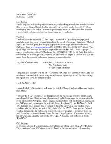
“Mondo-MIJ” Part 3:This part of the “Mondo-MIJ” mod is perhaps the most complicated, yet also potentially the most unique. The inspiration for this part of the “Mondo-MIJ” modcame from an article by Jack Orman where he described alternative distortion saturation and blending configurations.This part of the mod replaces the hard clipping diodes in D4 and D5 with a network of diodes that are blended together to create a mixed distortion sound.Mondo-MIJStockNOTE: The wire between the center (common) lugs of the DPDT and B100KΩ pot does connect to both center lugs. Strip the wire about ½” and feed it throughboth lugs before soldering.The DPDT toggle switch allows you to switch between crossover distortion and the hard-clipping distortion found in the since-retired MIJ-Plus mod. The B100KΩpot is used to blend the mixture with either more clipping from the LED hard-clipping diodes or the diode pairs controlled by the DPDT. NOTE: Once you’ve builtthis part of the mod into your “Mondo-MIJ”, you will notice that, other than the diodes controlled by the DPDT, you cannot really turn off any of the diodes inthis circuit. This is due to the fact that the DPDT-controlled diodes always have a path between signal and Vref, no matter what the blender pot is set at –and–the fact that the positive (signal) side of D4 and D5 are connected directly outside of this clipping circuit. The effect of the LED/1N34A clipping diodes can bereduced significantly (due to the 100KΩ series resistance presented by the B100KΩ pot), but due to the higher output level of that part of the circuit, their effectcannot be eliminated entirely.The result of all this blending is a fairly complex distortion with increased headroom, with the ability to “nudge” the signal towards smoother or moreaggressive/edgy, depending upon how you set the DPDT and the blender pot. Touch-sensitivity is vastly improved, allowing your picking dynamics to determinethe amount of distortion the circuit produces. (Meaning: pick softly and it cleans up dig in hard with the pick and it distorts, akin to similar behavior in tubedistortion circuits.)20
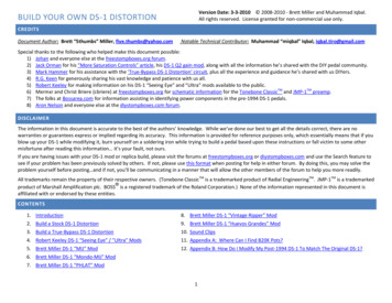
Here’s a diagram depicting how the Mondo-MIJ clipping section is wired:21
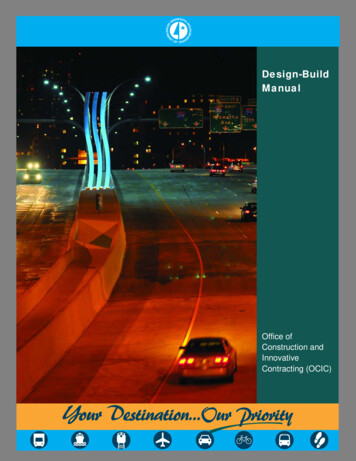
So now that I’m done with my basic discussion of the theory and design behind Part 3 of the “Mondo-MIJ”, let’s talk about actually building it.On all DS-1 variants, B100KΩ pots are used for both the LEVEL and DIST controls. Part 3 of the “Mondo-MIJ” also uses a B100KΩ pot as its blender control. Youmight think, “Two B100KΩ pots in a pedal already tight on interior space?!” My mind immediately thought “dual B100KΩ pot”, which is a good idea with somecaution. Since you will want either the LEVEL or DIST control to operate independently of the Blender control, you will need a dual concentric B100KΩ pot.These can be hard to come by, but at the time of this revision, GuitarFetish has some snazzy miniature B100KΩ dual concentric pots and knob sets that workvery well for this mod (pictured below on the left.) You might be able to find these pots and knobs elsewhere, but finding them in the B100KΩ variety is tough.If you can locate linear mini dual concentric pots in a larger resistance, you can solder resistors between lugs 1 and 2 plus lugs 2 and 3 (on both pots) to create a100K pot. (Visit Joe Davisson’s EMH page and click on ‘Linear Pot’ on the left side for help picking the resistor sizes to make a B100KΩ pot out of your pot.)On my DS-1, I chose to put the DPDT toggle switch below the TONE control (with the chassis hole approximately centered on the ‘O’ in TONE.) I replaced theDIST control with the dual concentric B100KΩ pot. I enlarged the hole slightly with a step drill bit and installed the pot. The GuitarFetish pot come preterminated with plastic connectors, which I decided to leave on, as they make for easier assembly/disassembly. To make pin connectors for the wiring and BOSS pot PCB mini-boards, use 22-gauge bus wire. Once you’ve assembled the connections for both the “Mondo-MIJ” clipping circuit and the DIST control, apiece of electrical tape around the connection will keep them from separating due to vibrations that normal handling and use produce. (If you want to skipdealing with the connectors, just cut off the terminals, strip the wires, tin the ends and solder them up directly.) Below in the center is an exterior shot of myfinished “Mondo-MIJ” DS-1.If you don’t want to use (or can’t find) a dual concentric B100KΩ pot, there is still hope. Get an Alpha 12mm B100KΩ pot from Mouser.com (Mouser partnumber 313-1210F-100K) and a small knob for it. Leave the LEVEL and DIST pots as-is and find some empty space on the upper-right side of the right verticalface of the pedal (with pedal sitting on its rubber base and knobs on top.) Space will be tight, but you should be able to drill that side and squeeze the pot inthere, having the knob protrude out of the right side of the pedal. In the above-right picture, I have marked the alternate location for the Blender pot with a red‘X’.22
Once you’ve done all that, test it, carefully box it up and revel in the satisfaction that you have created a great, new sound for your DS-1 –and– just fit 20 poundsof “fertilizer” into a 5-pound bag by fitting all that stuff inside the DS-1 chassis. To assist you in deciding if the Mondo-MIJ is right for you, the table below has links to sound clips demonstrating the Mondo-MIJ “blender” pot. FYI, these soundclips are supplemental to the other Mondo-MIJ sound clips found on the Sound Clips page, so please check those out as well.Mondo-MIJ through a Fender Bassman (4x10)1N34A crossover distortion selected on DPDT switchBlend Pot @ 7:00Blend Pot @ 9:30Blend Pot @ NoonBlend Pot @ 2:30Blend Pot @ 5:001N914 / NPN hard clippers selected on DPDT switchBlend Pot @ 7:00Blend Pot @ 9:30Blend Pot @ Noon23Blend Pot @ 2:30Blend Pot @ 5:00
BRETT MILLER DS-1 “PHLAT” MODThis mod is an alteration to the low-pass and high-pass filters that feed the TONE control of the DS-1. The intent of this mod is to give the user the option toswitch between the stock, scooped-mids tone and a flatter tone shape that will help keep the tone full-sounding at lower DIST settings.The stock DS-1 TONE control has a low-pass filter with a corner frequency of 234 Hz and a high-pass filter with a corner frequency of 3290 Hz. This produces theclassic DS-1 scooped mids tone that allows the harmonics produced by th
Have you ever wanted to build your own DS-1 Distortion, but could only find work-a-likes, schematics for the pre-1994 vintage _ DS-1 or just plain inaccurate . -difficult if you take your time and carefully assemble the pedal with the knowledge and skills youve developed in your previous pedal