Transcription
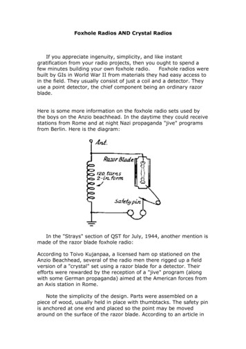
Foxhole Radios AND Crystal RadiosIf you appreciate ingenuity, simplicity, and like instantgratification from your radio projects, then you ought to spend afew minutes building your own foxhole radio.Foxhole radios werebuilt by GIs in World War II from materials they had easy access toin the field. They usually consist of just a coil and a detector. Theyuse a point detector, the chief component being an ordinary razorblade.Here is some more information on the foxhole radio sets used bythe boys on the Anzio beachhead. In the daytime they could receivestations from Rome and at night Nazi propaganda "jive" programsfrom Berlin. Here is the diagram:In the "Strays" section of QST for July, 1944, another mention ismade of the razor blade foxhole radio:According to Toivo Kujanpaa, a licensed ham op stationed on theAnzio Beachhead, several of the radio men there rigged up a fieldversion of a "crystal" set using a razor blade for a detector. Theirefforts were rewarded by the reception of a "jive" program (alongwith some German propaganda) aimed at the American forces froman Axis station in Rome.Note the simplicity of the design. Parts were assembled on apiece of wood, usually held in place with thumbtacks. The safety pinis anchored at one end and placed so the point may be movedaround on the surface of the razor blade. According to an article in
Popular Mechanics of October, 1944, the blued steel surface of theblade gives the rectifying action needed for detection withoutcrystals.Someone soon figured out a better way to use the razor bladedetector: use a pencil lead point on the razor blade. I built afoxhole radio in a few minutes using the previous diagram, but Iused a pencil point. I fashioned a safety pin shape out of stiff wire,then tied about an inch of pencil lead to it with finer wire. The radioworked the first time I tried it. Of course, with a fixed coil I receivedonly one station.The photograph shows a similar radio built by Don Menning; hesimply stuck the whole tip of a pencil on the end of the safety pin.
Here is the parts list for the schematic based on Lt. Cornell'ssubmission:(A) Antenna connection. This nail also fastens the coil form to thebaseboard.(B) Baseboard. 4 inches square, ¼ inch thick.(C) Coil form. Wood block, 3¾ inches long, 2 inches wide and ¼inch thick.(D) Area of coil scraped clean along arc of switch arm.(G) Ground connection. This nail also fastens coil form to baseboard.(J) Jacks for 'phones. Paper clips held down by tacks.(P) Detector. Pencil lead wrapped with copper wire and restinglightly on razor blade. Some adjustment of the location andpressure of the lead on the blade may be required.(R) Razor blade held down and connected to wire by tack.(S) Screw or nail for pivot of switch arm.(SA) Switch arm made from paper clip.(T) Thumbtack, or any kind of tack.(W) Coil winding, approximately 175 turns No. 26 insulated wire.In October of 1962, Popular Mechanics ran a construction articleby Joe Tartas which was almost identical to the above design. Mr.Tartas noted that GIs used their bayonets buried to the hilt in moistearth for a ground connection. You probably do not want to useyour vintage WWII bayonet in this manner unless you're a sticklerfor authenticity!As with any radio of this type, a good ground and a longantenna (50 to 100 feet) will give you best results. Don't expectroom-filling sound, but do expect a lot of fun from very little effort!The only part of a foxhole radio you don't build from scratch isthe 'phone. However, if you're really looking for a radio project builtentirely from scratch, you could try your hand at building one.If you take apart a 'phone, you'll notice they're very simple inconstruction. Basically, there's a coil with a small iron core.Electrical variations in this coil generate a magnetic field used toattract and repel a metal plate. This vibrating plate produces the(faint) sound you hear.
The March 1, 1994 issue of The Xtal Set Society Newslettercarried an article by Nyle Steiner describing how to build your ownhome-brew 'phone. Nyle used a coil made from 7000 turns of 0.004inch wire around a ¼ inch rod. For more information, check out thisarticle, or experiment on your own!Disclaimer: Working with antennas and electrical devices (especiallyold ones) can be dangerous, and mistakes can be fatal. If youdecide to work with such things, it is solely your responsibility towork safely and to know what you're doing. –DJAFoxhole - POW built radiosFoxhole and PoW built radios: history and constructionBuilding a foxhole radio is rewarding and the basic setup is verysimple. It is, however, difficult to adjust, and it may take severalattempts to find a proper razor blade for the detector. This is aproject that requires patience and much trial and error, but it willpay off once it begins to work. It will help to be versed in theconstruction and operation of crystal sets before building one. It willbe especially helpful to read the introductory notes about the coil,detector, antenna, and other components. These sets are extremelysimple in construction, but tuning and modification require somebasic understanding of theory, as well as practice. All setspresented here are based on old articles, notes, and people'srecollections. There are fairly major variations in design andmaterials among these plans. It must be remembered that thesewere improvised under often adverse conditions; there was no"standard" design. With this in mind, take this entire article as awhole, and use it a bit here, a bit there, to build towards a designthat works best using modern materials.Set 1GI's, during World War Two, built these sets which took advantageof (comparatively) readily available materials. The instructions arepurposely lacking in detail; these were a project designed with
improvisation in mind. It will help if you have had some experiencewith crystal sets before undertaking this project. It is very tricky totune and properly set the detector. But once you get it working, youwill be amazed that you can actually receive signals through socrude a device. This design has survived mostly thanks to the articleBuild a World War II Foxhole Radio by Lance Borden, as it appearedin the Electronics Handbook vol. XVII, p. 47.The basic components are:\Razor blade "PAL Super Single Edge" or a regular rusty oneCardboard toilet paper tubeWire coat hanger or other handy strip of workable metal Headphones or earphone (2 - 4 K ohms)Large safety pinLead from a wooden pencil#22 AWG (or so) wireSomething for a base (small scrap of wood)Lacquer, glueSmall tacks or screws for fastening componentsRefer to the schematic for wiring and connections. Wind the coil 100turns around the tube. #22 AWG wire is recommended, but it islikely that whoever was in the field used whatever gauge was in thescrap coil, motor, or transformer they were cannibalizing. Spray /paint the coil with lacquer (or whatever is handy) to set it firmly.Scrape off whatever paint or varnish may be on the wire used forthe tuner/slider. Spread the safety pin apart and bend the head 90degrees to use it as a base for attaching the pin to the base. The
pin should stick up from its bent head, then down to its point wherethe pencil lead is attached with some of the wire left from windingthe coil. The sharpened pencil lead is the detector, which touchesthe razor blade, which is in turn attached to the base at one of itsends (through the hole) with a screw or tack. The tuner should bemounted so that it is free to pivot and slide across the coil (see thecrystal radio page for basic construction tips). Use a scrap of paperor cardboard as a template for getting the tuner/slider the correctsize. Sand off the varnish on the coil where the slider will touch it.Connect the ground and antenna, hook up the headphones, andthrough much patient adjustment of the detector and slider, youshould eventually be able to pick up broadcasts. A capacitor (.001 .002 uF) between the earphone terminals improves performance. Ihave seen more than one example where a cap was improvisedfrom cigarette foil, cut into strips and stacks (the paper backingserved as the insulating layers). Simple variable capacitors(condensers) may have also been easily improvised.A note about the detectorThe blade of choice is an old fashioned disposable blue razor blade,which (according to some sources) was coated with a layer ofselenium oxide. This formed a point contact diode when coupledwith the pencil lead, demodulating the radio signal. A plain rustyrazorblade forms a point contact diode with iron oxide which doesn'tmake as good a detector, but will still work. You will need to try thepencil lead (sharpened) at several different locations (nearest theedge usually works best) to find the most sensitive point. You mayneed to adjust the contact pressure as well; the lead should touchthe blade fairly lightly.Note: There has been some debate as to what the blue coatingactually was. I had heard from one source that it was seleniumoxide; a reader, Tom Lee, believed it was carborundum. Tom laterwrote back:"I actually contacted the Pal Corporation, and they eventually didget back to me with an answer. The blue coating was simply anoxide produced by heat treatment of the blade. No special atoms ofany kind. She also said that Gillette and some others producedcompetitive blue blades that were made in the same way."Thanks for doing the research, Tom!Another reader writes that he had success using a blued hacksawblade (he didn't specify how big of a piece) and a hard drafting lead.These days, a blued hacksaw blade is much easier to find than ablued razor blade!
Set 2The simplest of these wartime sets didn't include a slider/tuner arm,and were therefor capable of only tuning in one frequency. Anarticle appeared in a 1944 issue of QST, and is faithfully reproducedin the D J Adamson Collection pages, so I won't go into a lot ofdetail here except to include the schematic. I highly recommendvisiting Mr. Adamson's pages if you are interested in old radio (orstereography).Not much can be said about so simple a design. The coil was 120turns around a 2" form (toilet paper tube). The whole thing wastacked down to a board. Pencil lead wasn't used at the time, insteadthe safety pin point directly contacted the blue (or rusty) razorblade.There is no tuner, of course, so only one signal will be received, andonly if there is a station broadcasting near the correct frequency!Set 3I have been told that often these radios were constructed evenmore simply. The whole thing would have been built on a small, thinpiece of wood or shingle, about 1/8 to 1/4 of an inch (3-6 mm)thick, 1or 2 inches (25-50 mm) wide, and 3 or 4 inches (75-100mm) long. The coil was wound around one narrow end (I am not
certain how many times. start with 100 and experiment). The bluerazorblade would have been screwed or tacked down (at one of itsends) at the other end. The safety pin and pencil lead (if there wasa pencil lead, which there probably wasn't) would have been riggedup in the same manner as in the above sets.From what I can tell, there would have been only 3 terminals, onesecuring the antenna wire and one end of the coil; one with thedetector (bent safety pin head) and one of the headphone wires;and one with the razorblade, ground wire and the other headphonelead. I have not built one of these. This is based on a sketch I madewhich in turn was based on the description of someone I brieflychatted with a long time ago, who himself constructed the thingmuch earlier. It is possible something was left out, so it may take alot of tinkering to get it to work (if it works at all). Once I getaround to building one of these myself, I will add to this pagewhatever tips I can (assuming I can get it to work!) I would alsoenjoy hearing if anyone else completes a working model.Set 4I have recently come across a sketch of a set that looked exactlylike set 2 on the Crystal radio page, except it had arazorblade/pencil detector where the diode would have gone.There was no "standard" design. They all used razorblades, usuallyblue, but the other components and configurations varied greatly. Ihave even seen a reference to a set that uses two blades, stuckwith one business end in the board, and inch or so apart. I don'thave any details about the circuit, but wires ran from each blade,presumably either between one of the headphone terminals and the
antenna, or between the ground and the antenna. A pencil leadspanned the blades, resting on the sharp edges.Set 5This is paraphrased from the article "How to Build a 'Foxhole Radio'", fromAll About Radio and Televisionby Jack Gould, Random House,1958.The illustrations are by Bette Davis (a different Bette Davis, Iimagine). The book is long since out of print, and too dated for mostlibraries to hold a copy. It is a simple set, much like Set 2, butcuriously it does not include a slider for the coil, even late in thearticle after the razor blade is dropped for a crystal and a condenseris added.Tools required are: A hammerA pair of pliersA pocket knifePartsBoard, at least 8 inches by 6 inches (200 by 150 mm) Cardboard tube, 2 inches in diameterby 6 inches long (50 mm by 150 mm)Insulated (enameled) copper wire, 28 gaugePair of crystal earphones (which in 1959 cost 2-3 dollars U.S.)3 new nails4 metal thumbtacks (not plastic push pins)A used blade that fits a safety razor. A plain white looking bladeoften works better than "blue" blades (direct quote)
Big safety pinPencil with a fat leadMake 4 little holes in the cardboard, 2 at each end, with one of thenails. Push about 6 inches (150 mm) through hole 2, and then pullthe wire up through hole 1. Wind the wire around the tube, makingsure the turns lie side by side and not on top of one another. Windfor a total of 120 turns. Afterwards measure off 6 more inches ofwire at the end and cut. Push the end of the wire down through hole3 and up through hole 4. Lay the coil on its side at the back of theboard. Fasten it to the board with 2 thumbtacks, making sure thethumbtacks do not touch any of the wire.The razor blade is placed in front of the coil. Lay it on the board,and gently fix it in place with two metal thumbtacks. Do not pushthe thumbtacks all the way in.Sharpen the pencil so there is a long piece of lead showing. Breakoff the lead, and wire it to the tip of the safety pin. Bend the headof the pin back so that it will lie flat on the board. Place the pin tothe right of the razor blade. Hammer a nail through the head of thepin until it almost touches the pin.Remove the insulation from the ends of the wires coming from thecoil, as well as from the ends of all wires used to make connections.Hammer a nail just to the left of the coil. Leave it sticking up just abit. Wrap the bare wire from the end of the coil around this nail.
Take another wire and wrap a bare end around the thumbtackholding the left side of the razor. Push the tack all the way down tomake contact. Take the other bare end of the same wire and wrap itaround the nail.Hammer a nail to the right of the coil and attach the coil wire asabove. Use another wire to connect from this nail to one of theterminals of the earphones. Take another wire and wrap the bareend around the nail holding the safety pin. Hammer this nail in tohold the wire in place, but not so tightly that the pin cannot move alittle. The other end of this wire attaches to the other free end ofthe headphones.The antenna attaches to the nail that connects with the coil andrazor blade (A). The ground wire attaches to the other nail, wherethe coil connects with the earphones (B). Hook up the headphones,and gently move the pin and pencil lead across the razor blade untilyou hear a broadcast. Once you hear it, don't move the pin,because you are more than likely going to lose it if you do. If thereare more than one stations nearby broadcasting near the samefrequency, you are likely to hear overlap. To solve this, you can adda condenser. A variable type can be used, as in the illustration. It isrecommended that it have 17, 19, or preferably 21 plates. Or youcan use a fixed capacitor of around .002mF, or you can build yourown (see the condenser article on the Crystal page). If a variablecondenser is used, the post attached to the fixed plates should beconnected to the nail that connects the coil to the blade (A). Thecondenser's other post is attached to the other nail (B). Once astation is found using the pin and blade. The condenser is turneduntil the signal becomes clearest. Also note that in the illustration acrystal and detector have been substituted for the razorblade. Thewire that was attached to the blade is attached to the crystal's post,and the wire that was attached to the pin is attached to thedetector's post. A safety pin can still be used instead of the catwhisker (see the introduction of the Crystal page).POW RadioPrisoners of war during WWII had to improvise from whatever bitsof junk they could scrounge in order to build a radio. One type ofdetector used a small piece of coke, which was a derivative of coaloften used in heating stoves. The piece of coke used was small,about the size of a pea. A small board was used and a depressionwas cut into it near one end to hold the coke. A screw and, ifavailable, a screw cup were used to hold the coke in place. A wirelead to the receiver was run from this to the coil/aerial (see Set 5).
A foot or so (30cm) of steel wire (guitar wire, piano wire, etc.) waswound around a pencil, long nail, or similar, leaving about one inch(25 mm) unwound at each end. The wireshould be somewhat springy.A secondscrew and screw cup is set about 3 inches(75 mm) from the first. Attached by thisscrew are one end of the steel wire springand a second lead, which is connected to one lead of theheadphones or earphones (if anyone has any information on howearphones from these sets may have been improvised, I would liketo hear about it). The steel spring wire was then stretched so that itjust rested on the coke. After much adjusting of the point of contacton the coke and the tension of the wire, some strong stations wouldhave been received.If the POW was lucky enough to scrounge a variable capacitor, theset could possibly receive more frequencies.A POW camp radio's construction describedThe Centre for the History of Defence Electronics Museum hasposted an amazing interview with Lieutenant Colonel R. G. Wells,who built a rather elaborate set out of scrounged and improviseditems while in a POW camp during WWII.Improvised diodeIf you want to try your hand at making your own diode, AllanCharlton, of Sydney, Australia, adds:"When I was a kid in a small town in Tasmania, Australia, ourschool was at the base of a hill, and the local radio transmitter wason top of the hill. We had lots of fun with crystal radios.
This is how we made our diodes:Take a small length of glass or plastic tubing--an inch of the case ofa plastic pen works well. Close one end with wax, sealing a wirethrough the wax. Pour a little copper oxide into the tube: enough tocover the end of the wire. Fill the rest of the tube with copper filingsor turnings. Poke a wire into the copper filings or turnings (but don'tlet it go down to the oxide) and seal the end of the tube with wax.Can't find copper oxide?Throw some copper wire into a fire. When it's cool, scrape the oxideoff the wire. Yes, there are two oxides of copper, a red oxide and ablack oxide, and they both work well. We preferred the red, but Ihave no idea why."But what about the earphone?Richard Lucas, who was a POW in Vietnam, built a radio in campand was also able to improvise an earphone. He writes:Four nails were bound together with cloth from our clothes.Wire was obtained from wire used around the camp which I mightadd wasn't coated with varnish. It was bare wire, so we wound alayer and, using a candle, we dripped wax over the turns, whichwere spaced as closed as possible without shorting out (nottouching). We repeated this process over and over again until wehad about 10 layers of wire, which were insulated from each otherlayer by a strip of cloth and wax. Then we put this in a piece ofbamboo and adjusted it so it was about a 1/32 of an inch from theend.A tin can lid was positioned over the coil of wire and nails. Thenconnecting it to our "foxhole radio" (basic design as yours) we couldhere about three radio stations. Our antenna was the barbwirearound the camp and the ground was wire laid along the ground tomake up the ground. Best listening was at night and it had to bepretty quiet because the earphone was pretty weak. If we had amagnet to set up a bias on the coil, the volume would have been alot louder."And Mike Barnard points out that "the headphones were almostalways acquired from a tank crew's radio operator, and often oneside of the headphone was cannibalized for wire to wind the tuningcoil while the other was used for listening."A radio constructed in the Milag PoW campGabe Thomas, who is the President of a Merchant Navy POW society,generously donated the following accounts, which occurred at theMilag Nord, the German PoW camp for Allied Merchant seamen:
"As you can imagine, when a ship's company gets captured, thereare men with a wide range of skills and interests. Naturally thecamp had a fair share of radio operators. The "official" unofficialcamp radio used the camp electrical circuit as an antenna after"lights out" when power was switched off. Where this radio camefrom I do not know, although I do know that trade between POWsand German guards and civilians did bring several radios into camp(cigarettes, coffee and soap from Red X parcels being the mediumof exchange.)I also know that the UK secret service had radio componentssmuggled into the camp via parcels from families and "well wishers".It appears that the Red X parcels were never used for contraband!One POW told me that his way of earning "pocket money" from hisfellows was to make crystal radios. I asked him where he obtainedhis crystals and he said that the Germans delivered cart loads ofashes to the camp to surface muddy paths. Graham "Speedy"Spiers made a fine wire sieve and would riddle these ashes to finduseable quartz crystals. He reckoned that he would find one every 2or 3 days.(This is) a radio made/used in Milag Merchant navy PoW camp inGermany in WWII. The radio was made from the bakelite case of astick of shaving soap. The radio belonged to Edward Roberts andRobert Durant. Shellac covered wire from a stolen guard's bicycledynamo was wound around the shaving stick case. Insulation wasscraped off a portion of the coil for adjustment.Edward Roberts was an apprentice (officer cadet) on the Delambre(Lamport & Holt Ltd. 7032 tons) which was sunk on the 7/7/40 by
the German commerce raider Thor. Between 38 and 44 survived tobecome prisoners.Robert Durant was an apprentice (officer cadet) on the Simnia,6197 tons, owned by the Anglo Saxon Petroleum Co. She was sunkby the German Battleship the Gneisenau on 15/March/41 between 8& 17 (accounts vary) survivors ended up in MILAG. Also in thecamp was Frederick Warner, Radio officer from the ship BritishStrength. Before capture he had been on Marconi's developmentstaff, experimenting with short wave transmissions. He madenumerous radios and before liberation (April 27th 1945) he hadmade a transmitter. George Waugh, from British Commander,apparently spent most of his waking moments winding coils fromwire "acquired" by those on outside working parties. These workingparties were always on the look out for useful objects to steal andany telephones or electric bells were fair game for theft. As yousay on your site, tank crew headphones were highly prized. Thecamp electric was switched off at night so the whole circuit becametheir antenna.There was one main radio, a German Peoples Radio, that by decreehad only a fixed bandwidth to prevent the German populationtuning to Allied propaganda. This radio had been stolen from thelocal village doctor and with so many radio officers in the camp itdidn't take long to modify it. Fortunately the power remained on inthe camp theatre hut at night and the radio was in the charge of"Robbo" Robinson, the theatre props manager.A map, updatedfrom the radio reports, showing the progress of the Allied forcesafter D day was kept pinned behind the door of one room where theGerman guards never thought to look. All that is except one of themore sympathetic German officers, Henschel, who used to come fora quick look to see how badly Germany was doing!
Crystal RadiosA crystal radio set is able to detect radio signals without a powersupply. It works best if there is a transmitter within 25 miles (40km) of the set. The antenna, a very long wire, picks up the wavesand passes them through the set as electronic current, and thendown to the ground. The set itself is a tuned circuit that can select adesired frequency from the many that are picked up by the antenna.The electric signals cannot be directly converted into sound becausethey vibrate back and forth too rapidly. The crystal (or diode)between the tuned circuit and the earphones allows the current topass through in one direction only. The earphone contains a smallsolenoid and a thin metal plate. The current passing through thecircuit and then through the diode causes the solenoid to move,which in turn moves the metal plate, whose vibrations create (faint)sound waves in the air.A very simple crystal radio is not very selective, and if there aremore than one nearby stations broadcasting near the samefrequency, there will more than likely be some overlap, and you willhear two or more broadcasts at once. The solution is to add a tunerand a capacitor to the circuit. The coil length is what determines thefrequency the circuit is tuned to. A simple tuner effectively changesthe length of the coil by selecting how much of it is in the circuit. Acapacitor (condenser) helps refine the tuning further.A note about the crystal detector
It is a fairly simple process to make a working radio using a moderndiode for a detector. However, the reason these are called crystalsets is because the detector was originally a piece of crystal. Youcan still make your radio the authentic way with a crystal and cat'swhisker. Detector stands are still manufactured, one good sourcebeing Antique Electronics Supply, 6221 S. Maple, Tempe, AZ 852832856 USA (phone 602-820-5411). A crystal detector includes acrystal, a cat's whisker, which is a special thin wire that contactsthe crystal, and the stand that holds the components in place. Themost common crystal used is a small piece of galena, which is fairlycommon, and can be found in many rock and hobby shops. Thecat's whisker is most often composed of phosphor bronze. Once incircuit, the whisker can be moved about on the crystal's surface tofind the most "sensitive" spot. The pressure of the whisker on thecrystal is also adjustable. There are some other crystals that willwork, so there is much room for experimentation with crystalfragments that you may already have. Also, it is not absolutelynecessary to use a detector stand, and the cat's whisker can beimprovised with a safety pin. Although it will be less selective andmore difficult to adjust, it can be made to work quite satisfactorily.A small piece of rubber pencil eraser impaled on the safety pin helpsto insulate it from your fingers while adjusting.The coil, antenna, ground, and phonesThe coils for these sets are typically wound around a 1 1/2 to 2 1/2inch (38 - 64 mm) diameter core, using 75 to 150 turns of 24 to 20gauge wire. These are typical numbers, not critical. What is criticalis that the individual loops of wire around the coil are wrappedtouching the next one over, but that they do not ever overlap. It isalso important that whatever attaches the coil to the base can nottouch the coil's wire, especially if it is a metal tack or nail. A coat ofshellac or varnish helps to keep the coil together. Let it dry
thoroughly before using. If a wiper type switch is used, the varnishwill need to be scraped away along its path.Ideally, the antenna should be 100 feet ( 30 m) or so long, andstrung as high as possible. Insulated or non-insulated wire can beused. Either way, the un-insulated ends should not touch anythingthat will ground them. It is best if they are tied off to ceramic orplastic insulators, which can in turn be tied off between two highpoints outdoors, such as a tree limb and your house. Never stringan antenna anywhere where it has even the slightest chance ofcoming into contact with a power line, or in a place where you willneed to go near a power line to hook it up. Always take the antennadown if a storm or lightning is predicted. It is safe practice to add alightning arrestor to you lead wire. You can purchase in many radioand electronic hobby shops antenna kits which include the antenna,insulators, lead wire, and lightning arrestor.The ground wire can be attached to a metal cold water pipe, or to ametal rod stuck a couple of feet into the earth. Do not attach it to aline carrying gas or electricity.The headphones (or earphone) need to be high the impedance typedesigned for crystal sets. They are still available through electronicssuppliers and some hobby shops.
The capacitorThe capacitor, or condenser, though not essential for operation ofthese sets, does help to refine their use when it is added. Morecomplicated sets have a variable capacitor. For the simplest sets,however, a fixed capacitor of around .002 mF or so is sufficient. Acapacitor is also very simple to build. The Cub Scouts, being thegreat caretakers of crystal radio lore that they are, included thispicture in the 1954 edition of the Wolf Cub Book. It lackedannotation of any kind other than what is here. The most importantthing to know is that all of the tinfoil pieces need to be completelyinsulated from
gratification from your radio projects, then you ought to spend a few minutes building your own foxhole radio. Foxhole radios were built by GIs in World War II from materials they had easy access to in the field. They usually consist of just a coil and a detector. They use a point det