Transcription
University of Michigan2/9/06Physics 441-442Advanced Physics LaboratoryElectron Diffraction and Crystal Structure1. IntroductionIn classical mechanics we describe motion by assigning momenta to point particles. In quantummechanics we learn that the motion of particles is also described by waves, with the crucialparameters of the two viewpoints related through the de Broglie relation:h! pwhere p is the momentum, λ is the wavelength, and h is Planck’s constanth 6.626 ! 10"34 J # s 4.136 ! 10"15 eV # s .[1]To observe wave-like behavior, we require some kind of grating where the “distance between slits”is of order the wavelength. At typical laboratory energies, the electron’s de Broglie wavelength is oforder one Angstrom (10–8 cm), about the same size as the interatomic spacings in common crystals.The regular atomic arrays in crystals are thus perfectly scaled gratings for creating a “matter wave”diffraction pattern, measuring their wavelength, and verifying Eq. 1. As an added bonus, with theprinciple verified, the diffraction patterns then become powerful tools for the study of crystalstructure.In this experiment, you will use a cathode ray tube with a graphite crystal target that shows thediffraction pattern on the screen. You will verify the de Broglie relation, and analyze crystalstructures, including measurement of the inter-atomic distance in the crystal.2. Basic Principlesa. The de Broglie Wavelength vs. VoltageIn the cathode ray tube the electron is accelerated through high voltage V. Its energy andmomentum are then given byp2E eV2mSolving for the momentum, and substituting into Eq. 1 gives:h! 2eVmYou should verify for yourself that this can be re-written in the practical form[2][3]151.3[4]V (volts)Thus, a 150 V electron has a de Broglie wavelength of 1 Angstrom, and the wavelength should varyin inverse proportional to the accelerating voltage.! ( Angstroms) b. Crystal Lattice SpacingA crystal is a very regular array of atoms. The regularity can be quantified in terms of certain smallpatterns of atoms, called unit cells, which are repeated over and over again. Since the vertices of
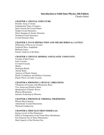
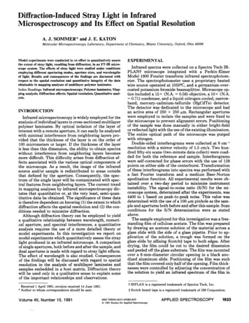
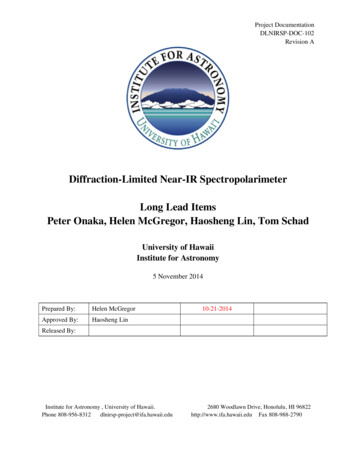
2/9/062Electron Diffractionthe unit cell are atoms, the size of the unit cell is related to the inter-atomic spacing, or latticeconstant, which is usually called a.This experiment will be done with a graphite (carbon) crystal that has a hexagonal structure. Fora simple hexagonal crystal such as graphite, the lattice is as shown below. The (100) and (110)planes, which respectively give rise to the inner and outer rings in the electron diffraction tube,are shown at right; the ratio of the d-spacings d100/d110 3 :1. These spacings have beendefined in terms of the unit vectors a and b where a b in the case of the hexagonal structure.The indices (100), (110), etc. are known as Miller indices.Figure 1: The unit cell and lattice spacings for graphite.c. Bragg ReflectionA rigorous description of crystal diffraction starts with a plane wave of electrons, treats each atom asan individual source of re-scattered spherical waves, and solves the three-dimensional problem ofsumming over all the expanding wavefronts. The standard solution is very interesting and elegantapplication of crystallography and Fourier analysis. You may enjoy the treatment in Chapters 1-2 ofKittel, which start from the diffraction problem and build up a theory of crystal structure, or Chapter4-6 of Ashcroft and Mermin, which start from crystallography and then develop an analysis ofdiffraction.However, as is frequently the case, there is a somewhat heuristic description based on a simplephysical model, which is easy to understand, and gets exactly the right answer. This picture wasformulated by W.H. and W. L. Bragg (father and son) in 1913, in order to explain very sharp peaksobserved at certain angles in the reflection of x-rays from crystals. This work won the Braggs theNobel Prize in 1915.Because it is really about the wave nature of the scatterer, the Bragg picture applies equally well toelectrons. We think of the regular array in the crystal in terms of planes of atoms. Each plane reflectswave like a simple plane mirror, with the angle of reflection equal to the angle of incidence (a.k.aspecular reflection).
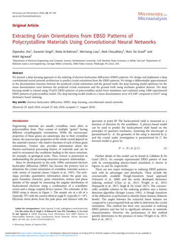
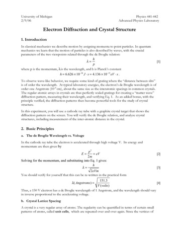
2/9/063Figure 2Electron DiffractionBragg's picture of crystal diffraction as multiple specular reflections.The sum of the reflections from a large number of parallel mirrors all separated by the same distance,d , will produce strong diffraction peaks when the angle between the beam and surface satisfies theBragg condition[5]2d sin ! n"In 1927, fourteen years after Bragg’s work with x-rays, Davison and Germer, working at Bell Labs,observed a strong diffraction peak in electron scattering from nickel. The wavelength of the “electronwave”, as calculated from the Bragg formula and the lattice constant of nickel, was exactly as predictedby de Broglie. This was verified shortly thereafter by G. Thompson in Scotland.De Broglie got the Nobel Prize in 1929. Davison’s result was completely accidental (see Serway forthe funny story). Thompson, who verified that the electron was a wave, was the son of J.J. Thompson,who discovered that the electron was a particle! Davison and Thompson got the Nobel Prize in 1937.d. The “Powder Method”The Bragg picture tells us that a beam of fixed wavelength (i.e. fixed energy) striking a crystal at theright angle will have its reflection reinforced by constructive interference. The obvious experimentalplan is to measure scattering intensity vs. angle. However, given a single uniform crystal, the not-soobvious problem is how to sample all of the possible angles. One way to do this is to hold thedetector fixed and rotate the crystal. Alternatively, one could vary the beam energy, hoping to hit theright wavelength for the unknown orientation of the crystal.The problem is nicely finessed by the idea, due to Debye and Scherrer, to use a powder or polycrystallinesample. A poly-crystal is a conglomerate of a large number of small crystal domains, where eachdomain is large enough to embody the “true” crystal structure, but all of the domains are orientedrandomly with respect to each other. (Why would crystals form in this way?) A beam incident on abulk sample will find many domains oriented at the correct Bragg angle for the beam energy. Thinkthrough the simple geometry of this and convince yourself that the locus of the strongly reflectedwave will be a cone with half-angle equal to twice the Bragg angle.The situation is shown schematically on the left in Figure 3. This technique also naturally projects adiffraction pattern onto a screen, for easy analysis via photograph or similar technique.
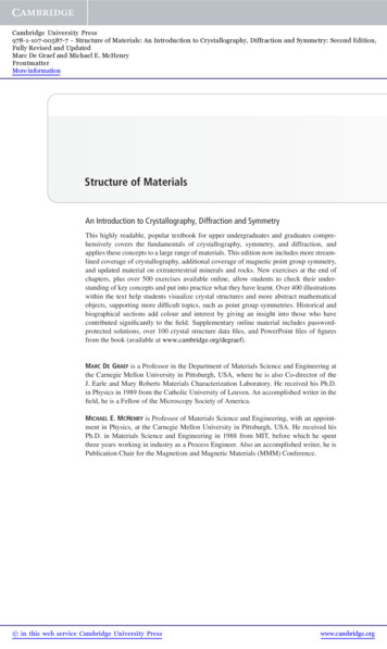
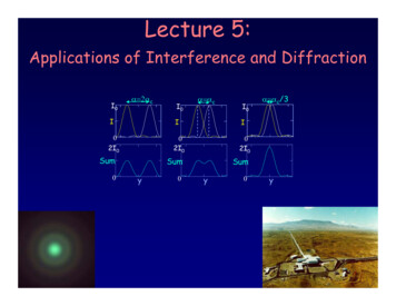
2/9/064Electron DiffractionFigure 3 Left: The Debye-Scherrer technique. Right: The diffraction pattern of Au. (Eisberg & Resnick)The diffraction maximum traces a circle in the projection plane. The circle is the base of a cone whosehalf-angle is given by R'[6]! 2" Bragg tan #1 & )L% (where R is the radius of the circle, and L is the distance from the target to the screen. Combining thiswith the Bragg condition, and assuming R L givesdRnh[7] n! L2eVmand thus, if L and λ are known, measurement of the radius yields d, the distance between Braggplanes. Electron diffraction becomes a tool for measuring inter-atomic distances in crystals and, as wewill see, the rich detail of crystal structure. Debye won the Nobel Prize in 1936.e. Some CrystallographyA pattern using polycrystalline gold is shown on the right of Fig. 3. The prediction of a circulardiffraction pattern is correct, but there are many maxima. We must conclude there are many differentBragg planes with different separations. In fact, this is a simple consequence of the fact that in a fixedlattice structure, there are many ways to “draw planes”. A two dimensional example is shown in Fig. 4below. Besides the obvious “horizontal and vertical” rows as in Fig. 2, we can draw a set of planeswhere each atom is “2-down and 1-over” from its neighbor. The distance d between these planes isdifferent from the distance a between atoms, leading to a different Bragg angle, and thus a differentring radius compared to the situation shown in Fig. 2. Each of the many other ways to make planes(“2-down, 2-over”, etc.) leads to a different d, a different circle, and the possibility of the complexpattern in Figure 3.The three dimensional version of the array in Fig. 2 is called a simple cubic array. There are two otherkinds of cubic arrays, face-centered, and body-centered, shown in Fig. 5. And there are many otherkinds of non-cubic crystal arrangements (hexagonal-close-packing, diamond, etc.), as well as thepossibility of mixing up different atomic species (leading to periodic patterns in a). The ways to“draw” Bragg planes are different in all these structures, and electron (or x-ray) diffraction is a methodof choice for understanding and distinguishing them.Understanding the physical correspondence between the diffraction pattern and crystal structurerequires a formalism for describing the crystal lattice. The careful treatment of this problem is a
2/9/065Electron Diffractionfascinating mathematical exercise, the basis of crystallography, and the starting point of solid-statephysics. We urge you to study the treatment in the references.Figure 4 A Bragg plane in a 2-D “cubic crystal”, and itsnormal vector u, whose numerical coordinates in the a1 a2basis are the Miller indices.Figure 5 Unit cells of the Simple Cubic, Body Centered Cubic, and Face Centered Cubic Arrays (Kittel)For now, however, we lay out a simple, physically appealing construction, with some impliedterminology from crystallography. We are interested to specify the “Bragg planes” and the distancebetween these planes. A plane is specified by its normal vector. Consider the two-dimensionalrepresentation shown in Fig. 4. The lattice constant is a. The unit-cell for this lattice is a square ofside a. The primitive-vectors are vectors of “unit-length” a, defining coordinate axes in directionsalong the sides of the primitive cells. The Bragg planes for “2-down and 1-over” are shown. Theperpendicular vector to these planes, u, is “2-over and 1-up”. In the business, this is called the “(2,1)plane”. The numbers 2 and 1 are called Miller indices. In three dimensions, the Miller indices for aBragg plane are the smallest set of integers (h, k, l) that specify the direction of the normal vector inthe basis defined by a1, a2, and a3. Some examples for the simple cubic lattice are shown in Fig. 6.
2/9/066Figure 6Electron DiffractionSome Bragg planes of the SC lattice (Kittel)Having a way to label the planes, the remaining problem in understanding the diffraction pattern is tospecify the distance, d, between the planes. The general solution is an elegant exercise in crystalsymmetry and Fourier analysis, and is discussed in the references.13. Experimental Techniquea. ApparatusThe electron diffraction tube is a small cathode ray tube (CRT) similar to that in a small (oldfashioned) TV set. The electrons pass through a target that consists of graphite, only a few molecularlayers thick, vapor-deposited on a micromesh nickel grid. The target is crystalline in tiny regions, so a"powder" diffraction pattern results, seen as a pair of rings around a central spot on the luminescentscreen. See diagram below. The distance between the target and phosphor screen is L 13.5 cm.Figure 1 Schematic of the CRT tube1The normal vector, u, is an element of the reciprocal lattice. An interference maximum will occur if the change in theelectron wave-vector Δk is a vector of the reciprocal lattice! See Ashcroft and Mermin or Kittel.
2/9/067Electron Diffractionb. Experimental Procedurei.Familiarize yourself with the apparatus, a Leybold electron diffraction tube with agraphite target. A power supply provides high voltage that can be varied between 0 and 5 kV.Set the high voltage to 0 with the slider control before turning on the power. Change the HVand understand qualitatively the response of the electron beam. Determine the lowest voltagefor which patterns can be obtained. Measure the radius R of the two rings from the graphitetarget for 5 or more voltages between about 2 and 5 kV. A good way to do this is to place apiece of masking tape across the tube face and mark the center and radii on the tape. You canuse the clip-on magnet on the neck of the tube to center the spot. To prevent overheating thetarget or burning out the phosphor on the screen, please turn the HV down when you are notactually making measurements. You’ll need to turn the room lights off to see the rings clearly.ii.Check the calibration of the HV meter using a high-voltage probe (if available).c. Analysis of DataPlot R vs. V-–1/2 including estimated uncertainties for both sets of rings. [Don’t forget that (0,0) is apoint also!]Determine the two lattice spacings, d110 and d100 for graphite, and estimate their uncertainties.4. ReferencesC. Kittel, Introduction to Solid State Physics. This is a standard source book for Solid State.Chapters 1 and 2 of this book will make you an expert at this experiment. Chapter 1 is anintroduction to crystal structure. Chapter 2 starts from diffraction and builds the necessary theory tounderstand it for cases beyond the cubic lattice.N. Ashcroft and D. Mermin, Solid State Physics. This is the other standard source book for SolidState. Chapters 4 through 7 lay out the issues of crystallography and diffraction that concern us. Amore sophisticated treatment than Kittel.H.P.Myers, Introductory Solid State Physics. See Chapters 2 and 3 for crystallography anddiffraction.R. Eisberg and R. Resnick, Quantum Physics of Atoms, Molecules, Solids, Nuclei, andParticles. This book has everything. The de Broglie hypothesis, “matter waves”, and a short historyof crystal diffraction experiments are discussed in Sec. 3.1. A nice quick overview of the principles ofcrystallography is given in Appendix Q.R. Serway, C. Moses, C. Moyer, Modern Physics. Sec 4.2 has a nice discussion of the DavissonGermer experiment, Bragg scattering, and “matter waves”.
2/9/068Electron Diffraction5. Questions(1) Estimate the error introduced into these measurements by the curvature of the tube face.(2) Are the data compatible with R V–1/2 as implied by Eq. 7? Have you verified the de Brogliehypothesis? Have you observed the wave nature of the electron? Discuss your results.(3) Compare the ratio of the two lattice spacings to that expected for a hexagonal lattice like graphite.(4) Graphite consists of layers of carbon atoms with an average separation between layers of 3.40 Å.Assume that each layer has the hexagonal structure shown below. Use the following information tocompute the nearest neighbor distance x between atoms within each carbon layer. A convenientchoice of unit cell is the equilateral triangle shown below. Some useful numbers are:N Avogadro's Number 6.02 x 10²³ atoms/moleW Atomic weight of carbon 12 g/moleρ Density of graphite 2.25 g/cm3Hexagonal structure of graphite(5) Calculate the average spacing between carbon atoms and compare it to the two measured latticespacings and the nearest neighbor distance from Question 4.(6) What evidence has this experiment provided to demonstrate that the crystalline structure ofgraphite really is hexagonal?(7) Give one example of the electron showing its particle-like nature in this experiment. Give oneexample as to it showing its wavelike nature.
However, given a single uniform crystal, the not-so-obvious problem is how to sample all of the possible angles. One way to do this is to hold the detector fixed and rotate the crystal. Alternatively, one could vary the beam energy, hoping to hit the right wavelength for