Transcription
gHigh Voltage Disconnect SwitchesFlexible design configurations from 72.5 - 800kVwith PrimaryPlusTMPre-engineered solution set that digitizes XD GE primary equipment and provides factoryinstalled and configured protection, monitoring, diagnostics and communications.GEDigital Energy
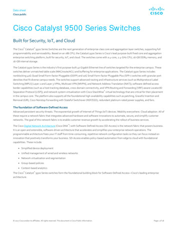
Disconnect Switches — 72.5 - 800kVGW11-363kV Disconnect SwitchGW4-145kV Disconnect SwitchTechnology Solutions for Global UtilitiesFor over a century, utilities have relied on GE to deliver electrical productsand services to meet their reliability and operational performance needs.GE is a leading provider of transmission and distribution solutions as well asgrid automation systems that maximize utilities operational efficiencies andprovides their customers with reliable power.With decades of experience, GE has brought reliable transmission anddistribution products to utilities around the globe. GE has manufactured andpartnered to install equipment in nearly 40 countries on five continents, weknow what it takes to meet our customer’s power needs around the world.The XD GE alliance brings end-to-end transmission and distribution solutionsto meet the global growing demand for electricity. The combined portfoliosof GE and XD will provide one of the most comprehensive sets of technologysolutions for customers in the utility sector and energy intensive industries.The XD GE disconnect switch facilities are ISO certified and have industryleading positions in quality, innovation, and field reliability with more than58 years of experience. The disconnect switch is manufactured in the samefacility and follows the same strict design and manufacturing standards asthe GIS and circuit breakers products.Through an alliance with XD Electric, GE has extended its portfolio toinclude all high and ultra-high voltage power equipment. XD Electric isone of China’s largest primary equipment manufacturers dedicated to theresearch, application and development of high and ultra-high voltage powerequipment. XD Electric is a premier high voltage breaker manufacturer inChina with world-class design capability.2GEDigitalEnergy.com
Disconnect Switches — 72.5 - 800kVKey Features Flexible design configurations from 126 – 800kV includingboth horizontal and vertical configurations; center, side,double side, and V break designs Designed for minimum but reliable clearance betweenphases & vertical length Conductive parts are constructed of light-weight, strongaluminum alloy Driving parts and balance spring are enclosed to minimizeenvironment exposure Hot dip galvanized process on all exposed iron and steelparts provide excellent anti-corrosion capability Height of porcelain and perpendicularity may be adjustedvia regulating bolts to ease installation Earthing switches are available at both ends of the frame Insulators are available in both ANSI 70 gray and IEC brownPrimary PlusXD GE offers Primary Plus on all its primary equipment.Primary Plus is a pre-engineered solution set that providesutilities with a means to reduce the time and labor associatedwith substation construction and expansion, while at thesame time utilizing technologies and methodologies familiarto existing resources.XD GE’s factory installed and configured solutions include: Digitized primary equipment by replacing labor-intensive,individually terminated copper wires with standardizedphysical interfaces and open digital communications Electrical protection systems optimized for the equipmentand application to monitor and react to fault conditions Highly secure and ruggedized communication networkequipment including industrial strength wireless, fiber opticmultiplexers and Ethernet switchesGW10/11-550kV Disconnect Switch
Disconnect Switches — 72.5 - 800kVOverviewIntroductionXD GE has more than 50 years of experience in disconnect switch research,development, and production. Advanced 3D design tools for simulation,assembly, and motion graphics help to improve the design quality and shortenthe design and manufacturing cycles. The disconnectors are manufacturedin a new 2,600 square meter workshop with an annual capacity exceeding2,000 sets per year.Key Functions I solating - Provide a visible isolating point to ensure crew safety whileperforming maintenance S witching– shifting equipment from one operation mode to anotherincluding operation, backup, maintenance Circuit Operation - can operate within the circuit with no or little currentGW4-145kV Disconnect Switch While open, disconnect switches show a visible opening point which meetinsulating clearance requirements W hile closed, disconnect switches carry working current as well as shortcircuit current within a specified timeTypical Environmental Conditions Altitude: 2000m above the sea level Ambient temperature: -50 to 55 C Maximum wind speed: 40m/s Earthquake accelerate: horizontal 0.3g, vertical 0.15g(or per customer request) Ice coating thickness: 20mm Maximum intensity of sunlight: 1000W/m2 Pollution: class III (heavy pollution), class IV (special conditions)GW7-363kV Disconnect Switch R elative humidity: daily average is not more than 95% ; month average isnot more than 90%Standards and CertificationsXD GE began designing and producing disconnects switches in the early1950s. Our disconnect switches are designed to meet rigorous internationalstandards including: GB1985-2004 IEC 60694 DL/T 486-2000 IEC 62271 - 1 DL/T 593-2006 IEC 62271 – 102 GB/T 11022-2011 ANSI 37.16, 30, 32GW11-420kV Disconnect Switch4GEDigitalEnergy.com
Disconnect Switches — 72.5 - 800kVProduct PortfolioTypeGW4GW4AGW4AGW4ARated Voltage72.5 - 252kVRated CurrentUp to 4000AShort Circuit withstand current/3sUp to 50kARated Peak Withstand CurrentType of Motor Operation MechanismGW7GW4AGW4AGW7BGW7BGW7B252 - AGW11AGW11AGW10AGW11AGW6GW6DGW6DGW6DGW6DGW6D126 - 550kV126 - 800kV126 - 550kVUp to 6000AUp to 5000AUp to 5000AUp to 4000AUp to 63kAUp to 63kAUp to 63kAUp to 63kAUp to 125kAUp to 160kAUp to 160kAUp to 160kAUp to 160kACJ6BCJ6A/CJ6UCJ6ACJ6A/CJ6UCJ6AMotor Operating MechanismCJ6 Series Motor Operating MechanismThe CJ6 series motor operation mechanism is easy to adjust, small in size, lightweight, and compact. The housing is constructed from stainless steel rivetedwithout welding resulting in an end product which is corrosion-proof as well aswater and dust-proof.Motor Interlock units are able to meet multi-interlock functions at the same time.Secondary wiring board The mechanisms are universal and meet the operating requirements of alldisconnectors and earthing switches made by XD GE.HousingFully enclosed reducer 2-step worm gear allows manual operation to be done reliably, smoothly, andwith low noise.Main Technical DataNo.Item1Electromotor2Heater3Control Loop4AuxiliarySwitchCJ6BRated VoltageRated SpeedRated PowerRated VoltageInput PowerRated VoltageRated VoltageRated CurrentContacts Number5OperatingMechanism67IPWeightTorsion angleRated TorqueClose TimeOpening Time380V (AC)1400rpm370W220V (AC)80W220V (AC)220V (DC)110V (DC)220V (DC)220V (AC)2.5A (DC)5A (AC)10 Normally Open10 Normally Closed1800 (900)200 700Nm4S, 8SIP6555KgGEDigitalEnergy.comCJ6A380V (AC)1400rpm550W, 750W220V (AC)100W220V (AC)220V (DC)110V (DC)220V (DC)220V (AC)2.5A (DC)5A (AC)10 Normally Open10 Normally Closed1800 (900)300 1200Nm4S, 6S, 8S, 9S, 10S,12S, 16S, 20SIP6575KgCJ6U380V (AC)960rpm750W220V (AC)100W220V (AC)220V (DC)110V (DC)220V (DC)220V (AC)2.5A (DC)5A (AC)10 Normally Open10 Normally Closed18002300Nm18S 2S, 24S 2S,32S 2S, 40S 2SIP65120Kg5
Disconnect Switches — 72.5 - 800kVGW4 Disconnect SwitchesCenter Break Disconnect SwitchGW4 series disconnect switches are structured in double columns for singlepole, one break, and horizontal rotary opening. There are two columns ineach phase. Supporting insulators at both ends are rotated horizontally bythe operating mechanism in performing the open and close operations. Themain conductive blade is mounted on the top of the supporting insulator. Amechanical interlock is mounted between the earthing switch and the mainblade to ensure a correct operating sequence of the disconnect switch andearthing switch.Conductive Rod Contact FingerKey Benefits A simple structure with fewer moving parts and lower operation torqueprovide reliable, steady operation throughout the product lifecycle. Capable of handling higher induced current and voltage and meet therequirements of IEC62271-102 standard type B. Convenient for installation and replacement due to independentinstallation of conductive rod and moving contact.Key FeaturesFlexible contacting outgoing baseThe soft connection is applied between the terminal and conductive rod,resulting in a design that is simple in structure with minimum contactresistance and high conductive reliability.GW4 Double Column Center Break Disconnect SwitchStrong current flow in conductive rod contact fingerThe conductive rod contact finger is constructed using aluminum alloy,resulting in a strong, light-weight design and a wide heat radiance area. Thestainless spring is located at the outside of the contacting plate to avoid shuntthrough the spring. The contacting plate and the flexible joint are moleculewelded under high pressure as a whole, with only one contacting point in thecurrent passage to ensure strong current-carry ability.The conductive rod contact head is made of aluminum alloy square pipe, thedesign is strong and light-weight with a wide heat radiance area.The contact results from bending the copper plate installed to the conductiverod. This enlarges the electrical conduction area and results in ease of themaintenance and component replacement. There is limited friction betweenthe plate contact and contact position in the switching operation.Accurate transmission and ease of commissionThe transmitting component is constructed using a stainless steel compositeshaft which is anti-corrosive with minor resistance force, and small fitclearance.The rotating parts and lever are positioned below the insulating porcelainand comprise the installing structure and ensure accurate transmission. Theporcelain bottle can be raised through the lifter making commission andadjustment easy to perform.6GW4 Double Column Center Break Disconnect SwitchGEDigitalEnergy.com
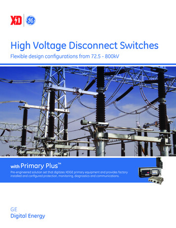
Disconnect Switches — 72.5 - 800kVGW4 Installation DimensionsGW4AFDA350ADEB&CAGW4 Dimensional TableAModel /2000GW4-126/3150GW4-252Nominal Ph-Ph Spacing(mm)160016002000200020004000BHeight of TermPad over Base(mm)125814261640168417802838CMaximum Height ofDisconnector over Base(mm)125814261640168417802838DSupport Insulator 2650EInsulator Height(BIL Related)(mm)8508501200120012002300F(Minimum Isolating Distance)Min. Metal to Metal w/ Switch Open(mm)71083016301630159022507
Disconnect Switches — 72.5 - 800kVGW7 Disconnect SwitchesDouble End Break Disconnect SwitchGW7 series disconnect switches are structured in three columns for singlepole, double breaks, and horizontal rotary openings. There are three columnsin each phase. Supporting insulators at both ends are fixed while the middleone can be rotated horizontally by the operating mechanism in performingthe open and close operations. The main conductive blade is mounted onthe top of the middle supporting insulator, and the stationary contacts areon the top of the other two fixed contacts. A mechanical interlock is mountedbetween the earthing switch and the main blade to ensure a correct operatingsequence of the disconnector and earthing switch.Key Benefits A simple structure with fewer moving parts and lower operation torqueprovide reliable, steady operation throughout the product lifecycle. Capable of handling higher induced current and voltage and meets therequirements of IEC 62271-102 standard type B.GW7 Three Column Double Break Disconnect Switch Rotary conductive blade design provides short operational torque, highcontacting pressure, self-clean contact, and strong ice-breaking capability. Ease of installation and replacement due to independent installation ofconductive rod and moving contact.Key FeaturesStationary Cast Aluminum Contact BaseThe cast aluminum stationary contact base is integrated with the wiringterminator with no welding joint on the conductive route. The arc strikedevice is used to switch the bus bar transferring current to limit the smallelectric inductance and micro-capacitor current. The fold-bend type contactstrengthens the current in conductive circuit and increase the clamp force.GW7 Three Column Double Break Disconnect SwitchCopper and Silver Moving ContactThe copper and silver moving contact uses welding technology to providea high level of mechanical strength and heat-conducting property aswell as prevent electronic corrosion. The conductive rod is constructed ofhigh-strength, anti-corrosion steel pipe which has powerful current-carrycapability, a wide heat radiance area, and better anti-corrosion performance.Robust, Seamless Steel Pipe BaseThe base is made of large-caliber seamless steel pipe which can meet thestrength requirements for supporting the product as well as reducing theoverall product weight.The base is a robust structure and its civil foundation can easily meet mostassembling criteria. The robust base can minimize the construction workloadand can prevent the switching faults caused by the foundation settlementcommonly seen with a segmented structure base.Stationary Cast Aluminum Contact Base8GEDigitalEnergy.com
Disconnect Switches — 72.5 - 800kVGW7 Installation DimensionsFGW7 70AADBECD115Disconnect SwitchOperating MechanismGround SwitchOperating MechanismGW7 Dimensional TableAModel #GW7B-252GW7B-363DWGW7B-420DWGW7B-500Nominal Ph-Ph Spacing(mm)3000/35005000User DefineUser DefineBHeight of Term Padover Base(mm)2850397047705048CMaximum Height ofDisconnector over Base(mm)3080424050405811DSupport Insulator sulator Height (BILRelated)(mm)2300340040004400F(Minimum Isolating Distance)Min. Metal to Metal w/ Switch Open(mm)13001800210023709
Disconnect Switches — 72.5 - 800kVGW10 Disconnect SwitchesVertical Pantograph Disconnect SwitchThe main blade of the GW10 series disconnect switch is a pantograph bladewith an insulated single break in the vertical direction at the open positionwith minimum clearance between phases and vertical length.Key Benefits G rading ring is added at stationary contact to improve electric fielddistribution and to effectively avoid corona. Auxiliary contacts are added at both stationary contact and movingcontact in order to avoid potential damages caused by electric arc duringopen and close operation. Conductive parts are made of high-strength aluminum alloy withperformances of light weight, large current endurance, large surface ofradiation, high corrosion resistance.GW10 Disconnect Switches Soft connection is used for conductive parts with simple structure andconvenient for installation. Balance spring is in parallel to reduce required operation force. Stationarycontact is almost in steady while operation. Supporting frame is hot-dip galvanized with high mechanical strength.Key FeaturesCopper and silver moving contactThe copper and silver moving contact uses welding technology to providea high level of mechanical strength and heat-conducting property aswell as prevent electronic corrosion. The conductive rod is constructed ofhigh-strength, anti-corrosion steel pipe which has powerful current-carrycapability, a wide heat radiance area, and better anti-corrosion performance.Insulator bearingsGW10 Disconnect SwitchesHeavy duty, double row ball bearings are used for GW10/11 type switches.They are exceptionally rigid and rotate with very little resistance. Factorylubricated and sealed stainless steel. They are completely maintenance free.Adjustable open and close position stopsPosition stops are provided for individual pole adjustments allowing maximumsynchronization of the three phase assembly.Disconnect Switch Test Facility10GEDigitalEnergy.com
Disconnect Switches — 72.5 - 800kVGW10 Installation DimensionsAAGW10AAAA"D"FAAEBGEHDGround SwitchOperating MechanismDisconnect SwitchOperating MechanismGW10 Dimensional TableModel -550DWANominal Ph-PhSpacing(mm)User Define3000User DefineUser DefineUser DefineBHeight of TermPad over Base(mm)15272688371543154715CMaximum Height ofDisconnector over Base(mm)370062158317947710877DSupport InsulatorDistance(mm)350425550550550EInsulator Height(BIL mF(Minimum Isolating Distance)Min. Metal to Metal w/ Switch Open(mm)21532550354041005100GDistance toSuspended Contact(mm)356259557960912010520HWidth ofDisconnector(Open)1440246531803460396011
Disconnect Switches — 72.5 - 800kVGW11 Disconnect SwitchesHorizontal Pantograph Disconnect SwitchThe main blade of the GW11 series disconnect switch is a pantograph bladewith an insulated single break in the horizontal direction at the open positionwith minimum clearance between phases and vertical length.Key Benefits G rading ring is added at stationary contact to improve electric fielddistribution and to effectively avoid corona. Auxiliary contacts are added at both stationary contact and movingcontact in order to avoid potential damages caused by electric arc duringopen and close operation. Conductive parts are made of high-strength aluminum alloy withperformances of light weight, large current endurance, large surface ofradiation, high corrosion resistance.GW11 Disconnect Switches Soft connection is used for conductive parts with simple structure andconvenient for installation. Balance spring is in parallel to reduce required operation force. Stationarycontact is almost in steady while operation. Supporting frame is hot-dip galvanized with high mechanical strength.Key FeaturesCopper and silver moving contactThe copper and silver moving contact uses welding technology to providea high level of mechanical strength and heat-conducting property aswell as prevent electronic corrosion. The conductive rod is constructed ofhigh-strength, anti-corrosion steel pipe which has powerful current-carrycapability, a wide heat radiance area, and better anti-corrosion performance.Insulator bearingsGW11 Disconnect SwitchesHeavy duty, double row ball bearings are used for GW10/11 type switches.They are exceptionally rigid and rotate with very little resistance. Factorylubricated and sealed stainless steel. They are completely maintenance free.Adjustable open and close position stopsPosition stops are provided for individual pole adjustments allowing maximumsynchronization of the three phase assembly.GW11 Disconnect Switches12GEDigitalEnergy.com
Disconnect Switches — 72.5 - 800kVGW11 Installation DimensionsGW11AAADEABCFGround SwitchOperating MechanismDisconnect SwitchOperating MechanismGW11 Dimensional TableAModel W11A-420WGW11A-420IIDWGW11A-550IIDWNominal Ph-Ph Spacing(mm)User DefineUser DefineUser DefineUser DefineUser DefineUser DefineUser DefineBHeight of Term Padover um Height ofDisconnector over Base(mm)2712463246326392732073208192DSupport Insulator 047605760EInsulator Height mum Isolating Distance)Min. Metal to Metal w/ Switch Open(mm)147025502550341639763976497613
Disconnect Switches — 72.5 - 800kVGW6 Disconnect SwitchesDouble Arm Vertical Pantograph Disconnect SwitchThe main blade of the GW6 series disconnect switch is a pantograph bladewith an insulated single break in the vertical direction at the open positionwith minimum clearance between phases and vertical length.Key Benefits Minimized clearance between phases and vertical length allowingplacement directly under the busbar. Conductive parts are made of high-strength, light-weight aluminum alloywith high mechanical strength. Driving parts are made from composite shall sleeve of three-layermaterial resulting in self-lubrication function, reduced friction, highreliability mechanical drive, and less operating force. Operating rod and rotating shaft are made of high-quality stainless steelor high-strength copper alloy.GW6 126 Disconnect Switch Driving parts and balance spring are enclosed in conductor pipes tominimize environmental impact.Key FeaturesCopper and silver moving contactThe copper and silver moving contact uses welding technology to providea high level of mechanical strength and heat-conducting property aswell as prevent electronic corrosion. The conductive rod is constructed ofhigh-strength, anti-corrosion steel pipe which has powerful current-carrycapability, a wide heat radiance area, and better anti-corrosion performance.Insulator bearingsHeavy duty, double row ball bearings are used for GW6 type switches. Theyare exceptionally rigid and rotate with very little resistance. Factory lubricatedand sealed stainless steel. They are completely maintenance free.Adjustable open and close position stopsPosition stops are provided for individual pole adjustments allowing maximumsynchronization of the three phase assembly.GW6 550 Disconnect Switch14GEDigitalEnergy.com
Disconnect Switches — 72.5 - 800kVGW6 Installation DimensionsAAGW6AAFCUSTOMERCONNECTIONTERMINAL PADEDBTERMINALPADTERMINALPADDISCONNECT SWITCHOPERATING MECHANISMCGHGROUND SWITCHOPERATING MECHANISMGW6 Dimensional TableModel #GW6D-126DWGW6D-252DWGW6D-550DWANominal Ph-PhSpacing(mm)16003000User DefineBHeight of TermPad over Base(mm)158526604740CMaximum Height ofDisconnector over Base(mm)4200619010965DSupport InsulatorDistance(mm)350425425EInsulator Height(BIL um Isolating Distance)Min. Metal to Metal w/ Switch Open(mm)167525504550GDistance toSuspended Contact(mm)3842594510427HWidth ofDisconnector(Open)20122630496015
72.5Disconnect– 800kV DeadTankSwitchesCircuit— 72.5 Breakers- 800kVState-of-Art Facilities and Rigorous Quality ProcessesManufacturing ExcellenceAdvanced Test FacilitiesXD GE utilizes a 2,600 square meter workshop with a production capacity of2,000 units per year to produce high quality disconnect switches across avariety of voltage levels.XIHARI is the Xi’an High Voltage Apparatus Research Institute and is anintegral part of the XD GE alliance. XIHARI has extensive testing capabilitiesat its facility sites, which include: High Power Laboratory, High VoltageLaboratory, Artificial Climate Laboratory, and EMC Laboratory and anOperational Test Circuit for HVDC Thyristor Valves. The testing facility forXD GE equipment is the largest testing hall in Asia, measuring over 40,000square feet and having a ceiling height of nearly 160 feet.XD GE has developed an advanced 3D CAE system to design, simulate andanalyze products. This system has improved manufacturing excellencethrough a shortened design cycle and reduced defects. According to thecharacteristics and usage of complex castings, engineers repeatedly studyand refine the optimum manufacturing process. In order to ensure thehigh quality mechanical processing requirements of core components, themanufacturing process includes machining center, whole-function horizontallathe, CNC drilling as well as high efficiency and precision CNC processingequipment.Exceptional QualityA focus on quality is an ongoing strategic initiative for XD GE and that isevidenced throughout the manufacturing environment. The quality processbegins with an incoming inspection of all materials to ensure the best possibleinputs before manufacturing begins.Throughout the production and assembly process, there are multiplecheckpoints in the documented test plan, including both visual and “stop flow”inspections. The production facilities follow strict non-conforming proceduresto identify, control and avoid the use and delivery of non-conformingproducts. Each production facility has developed strict environmentalstandards, including controls of cleanliness, temperature and humidity, andhas controls in place to monitor and manage to the established standards.In addition, XD GE has a dedicated measuring and inspection departmentwith certified, full-time inspectors in each of its manufacturing sites.The measuring and inspection department provides a secondary crossinspection for all work in process, as well as finished products, ensuringquality is achieved throughout the manufacturing process. Quality data ismaintained and analyzed, per product family, in order to drive continualproduct and process improvements and higher product reliability.From raw materials acquisition and inspection to finished product, XD GE’sdisconnect switches are designed to meet rigid quality processes that ensurethe installed product provides the highest level of reliability.16GEDigitalEnergy.com
Disconnect Switches — 72.5 - 800kVSupport and ServiceGlobal ProjectEngineering ServicesGE is dedicated to the success of its customers and provides an array ofcomprehensive services to help successfully deploy and maintain GEproducts and business solutions globally. World-class post-sales support,professional services, and supportive resources are ready to ensure thatyou effectively use the technical power and business advantages that comewith GE products.This support infrastructure covers the entire life cycle of the product.You can count on our GE global services team from the coordination oftransportation logistics through the completion of site acceptance testingand into warranty and support phases of the product life cycle.Disconnect Switch WorkshopAccess to our GE support team for post commissioning needs is simplified toa single phone number or email address. Our global support center will bestaffed 24x7 to field any incoming concerns and ensure our customer needsare fulfilled as quickly as possible.Our experienced and qualified GE field service team has significant reachand leverage across the globe. The field service team will also have accessto significant high-voltage power equipment domain expertise.Our dedicated global service team comprises of qualified service engineers,in addition to a global field service network to deliver world-class installation,commissioning and post-sales support.Specialized Installation & Commissioning Logistics including coordination of ocean and inland transportation Complete installation services include rigging,labor (mechanical and electrical) Receiving, rigging, and unloading Testing system commissioning Site acceptance testingPost-Sales / Installation Support 24x7 Global customer service with operatorsavailable to respond to customer requests Emergency response hotline Several customer support access points available toobtain support (telephone, e-mail, fax, or web) Warranty backed by the strength of GE We offer a global system of maintenance and repair facilities4800kV/720 kJ Impulse Voltage Generator & 2000kV 30mA DC Voltage GeneratorGEDigitalEnergy.com17
Disconnect Switches — 72.5 - 800kVPrimary PlusPre-Engineered Secondary EquipmentPrimary Plus, XD GE’s supplemental offering to its primary equipment, is a pre-engineered, factoryinstalled solution set that allows utilities to reduce the time and labor associated with substationconstruction and commissioning. Primary Plus uses technologies and methodologies familiar toexisting resources and skill sets. Digitized primary equipment for replacing labor-intensive, individually terminated copper wires Electrical protection solutions to monitor and react to fault conditions Secure and ruggedized communications infrastructure devices including wireless radios, fiber optic multiplexersand Ethernet switchesDigitized SubstationMultilinTM HardFiber SystemKey Benefits Using the Multilin HardFiber system, XD GEcan deliver primary equipment with digitalcommunications. The Multilin HardFiber systemdigitizes analog signals from primary assets utilizingIEC 61850 communications, reducing total lifecosts of protection and control through labor andresource optimization. Saves up to 50% of Protection & Controllabor costs This factory-installed solution reduces the amountof labor-intensive, individually terminated copperwire connections with pre-terminated copper andfiber optic cables with standard physical interfacesand open digital communications. Eliminates the majority of copper wiring to better utilize resources for the design,building, commissioning, and maintenance of power system protection and control Robust and simple architecture for deploying IEC 61850 process bus Improves employee safety by leaving potentially dangerous high-energy signalsin the switchyard Reduces the chances for operational mistakes made during isolation andrestoration after routine maintenance Built as an extension of the Multilin Universal Relay (UR) family of products,suitable for a wide array of protection applications Rugged, hardened, and secure switchyard interface enablingNERC/CIP complianceElectrical Protection & ControlAdvanced Relays for PrimarySubstation EquipmentPrimary Plus utilizes the Multilin C60 BreakerProtection system or Multilin F60 Feeder Protectionsystem to provide primary protection of critical substationequipment. Multilin relays are substation hardeneddevices that provide comprehensive protection, control,automation, and monitoring of high voltage substationcircuit breakers. With fast, deterministic execution ofprogrammable automation logic, extensive I/O options,and integrated high-speed peer-to-peer communications,Multilin protection devices can receive and executecommands and at a fraction of the cost when comparedto a traditional hard-wired configuration.18Key Benefits Advanced circuit breaker monitoringand control in a single platform Co
the GIS and circuit breakers products. Technology Solutions for Global Utilities Disconnect Switches 72.5 - 800kV Disconnect Switches 72.5 - 800kV. Key Features Flexible design configurations from 126 – 800kV including b