Transcription
EMBEDDEDSYSTEMSPROGRAMMINGWITH THEPIC16F877Second EditionBy Timothy D. GreenCopyright 2008 by Timothy D. GreenAll Rights Reserved.
Table of ContentsPreface . 5List of Figures . 6Abbreviations and Acronyms . 7Trademarks . 10Chapter 1 Introduction to ESP and the PIC . 11Chapter 2 Microcontrollers and the PIC16F877 . 15Section 2.0 Chapter Summary . 15Section 2.1 Memory and Memory Organization . 15Section 2.2 The PIC16F877 . 16Section 2.3 Programming the PIC 17Chapter 3 Simple PIC Hardware & Software (“Hello World”) . 20Section 3.0 Chapter Summary . 20Section 3.1 A Simple Example System 20Section 3.2 Summary of Instructions and Concepts . 25Chapter 4 The PIC Instruction Set (Part I) . 27Section 4.0 Chapter Summary . 27Section 4.1 The PIC16F877 Instruction Set 27Section 4.2 Summary of Instructions and Concepts . 33Chapter 5 The PIC Instruction Set (Part II) . 34Section 5.0 Chapter Summary . 34Section 5.1 Introduction 34Section 5.2 Keypad and Display Interface 35Section 5.3 The STATUS Register and Flag Bits . 39Section 5.4 The Keypad Software . 40Section 5.5 The LED Display Software 43Section 5.6 Improved Display and Indirect Addressing 46Section 5.7 Odds & Ends . 50Section 5.8 Using KEY SCAN and DISPLAY Together . 54Section 5.9 A Last Look at the Advanced Security System . 56Section 5.10 Summary of Instructions and Concepts 57Chapter 6 Fundamental ESP Techniques . 59Section 6.0 Chapter Summary 59Section 6.1 Introduction . 59Section 6.2 Software Readability 59Section 6.3 Software Maintainability . 602
Chapter 6Section 6.4 Software Fundamentals . 60Section 6.5 The Background Routine 61Section 6.6 The Watch-Dog Timer 61Section 6.7 Event-Driven Software . 62Section 6.8 Interrupts . 65Section 6.9 Slow Inputs and Outputs . 65Section 6.10 Software Time Measurement 66Section 6.11 Hashing . 67Section 6.12 Waveform Encoding . 68Section 6.13 Waveform Decoding 71Section 6.14 RAM, ROM, and Time Tradeoffs 75Section 6.15 ROM States . 75Section 6.16 Limitations of C/C 76Chapter 7 Advanced ESP . 78Section 7.0 Chapter Summary 78Section 7.1 Introduction . 78Section 7.2 Sine Wave Generation .78Section 7.3 Dual-Tone-Multi-Frequency (DTMF) Signaling 81Section 7.4 Pulse-Width Modulation .82Section 7.5 ADPCM Data Compression 84Section 7.6 Test Functions and System Ideas 87Chapter 8 PIC Peripherals and Interrupts 91Section 8.0 Chapter Summary .91Section 8.1 Overview of the PIC Peripherals 91Section 8.2 Input/Output Ports .93Section 8.2.1 Port A . 93Section 8.2.2 Port B, Port C, Port D . 95Section 8.2.3 Port E . 95Section 8.3 Interrupts . 95Section 8.4 ADC and Analog MUX . 98Section 8.5 Watch-Dog Timer . 102Section 8.6 Timer 0 103Section 8.7 Timer 1 . 105Section 8.8 Timer 2 . 106Section 8.9 Capture Mode 107Section 8.10 Compare Mode 109Section 8.11 Pulse-Width Modulation (PWM) 111Section 8.12 Parallel Slave Port 1143
Chapter 8Section 8.13 EEPROM Data Memory 116Section 8.14 FLASH Program Memory . 117Section 8.15 FLASH Code & Data EEPROM Protection . 118Section 8.16 The CONFIGURATION Word 119Section 8.17 Sleep Modes & Reset Modes 120Chapter 9 PIC Peripherals, Serial Communications Ports 122Section 9.0 Chapter Summary 122Section 9.1 Introduction .122Section 9.2 USART (Overview) 122Section 9.2.1 USART (Asynchronous Mode, Full-Duplex) .123Section 9.2.2 USART (Synchronous, Master Mode) 127Section 9.2.3 USART (Synchronous, Slave Mode) . 128Section 9.3 Serial Peripheral Interface (Master Mode) . 128Section 9.4 Serial Peripheral Interface (Slave Mode) 132Section 9.5 I2C System Overview .134Section 9.5.1 I2C Slave Mode 137Section 9.5.2 I2C Master Mode . 139Chapter 10 DSP Fundamentals 147Section 10.0 Chapter Summary . 147Section 10.1 Introduction . 147Section 10.2 An Example: A Low-Pass Filter . 148Section 10.3 An Example: A High-Pass Filter . 148Section 10.4 DSP Filters in General 149Section 10.5 Aliasing and the Nyquist Sampling Theorem 149Section 10.6 DSP Cookbook I: A Simple LPF/HPF . 151Section 10.7 DSP Cookbook II: A Simple BPF 152Section 10.8 DSP Cookbook III: A Median Filter 153Section 10.9 DSP Example I: Standard DTMF Decoding .154Section 10.10 DSP Example II: Alternative DTMF Decoding . 155Section 10.11 DSP Application: Speech Compression 159Appendix A The PIC16F877 Instruction Set . 163Appendix B Useful C Programs for PIC ASM Applications . 180Appendix C Special Function Registers (RAM Addresses & Bits) 185Appendix D PIC16F877 Register File Map 191Appendix E PIC16F877 Pin Function Map 192Appendix F Save/Restore Registers on Interrupt 193References . 1954
PrefaceThis book is intended for use by Junior-level undergraduates, Senior-levelundergraduates, and Graduate students in electrical engineering as well as practicingelectrical engineers and hobbyists and seeks to provide a gentle introduction to embeddedsystems programming with the Microchip PIC16F877 microcontroller. After introducingthe PIC16F877 and its programming, this book covers the fundamental techniques andadvanced level techniques of embedded systems programming in a general sense. Thegeneral sense ESP techniques can be applied to any microcontroller. There is also anintroduction to the fundamentals of digital signal processing (DSP) using the PIC16F877.I would like to thank Dr. Dan Simon of the Cleveland State University ElectricalEngineering Department for his kind and valuable help and suggestions in thepreparations for this book. I would also like to thank John R. Owerko and James R.Jackson, both of A.R.F Products, Inc., for their expertise in the security systems market.I owe them both a great debt for my knowledge of security systems and for expanding myknowledge of the techniques of embedded systems programming in general.Special thanks also go to Sister Renee Oliver who proofread the manuscript andoffered many helpful suggestions. Thanks go to my friends Damian Poirier, Jim Strieter,Greg Glazer, Zarif Bastawros, Brian McGeever, Ted Seman, and Jim Chesebrough whooffered many helpful suggestions.Any errors that remain in the text are mine and I will correct them in the nextedition.Timothy D. GreenNovember 2005Cleveland, Ohio5
List of Figures2-1 uP Internal View Block Diagram2-2 PIC16F877 Internal Block Diagram3-1 Simple Hardware View (Ports Only)3-2 Basic Hardware System Example4-1 A Simple Security System5-1 Twelve-Key Matrix Keypad5-2 PIC Matrix Keypad Interface Circuit5-3 Seven Segment LED Digit Display in Common Cathode and CommonAnode Forms5-4 Single LED Digit Drives for Common Cathode/Anode Forms5-5a Multiplexed LED Digit Drives for Common Cathode Form5-5b Multiplexed LED Digit Drives for Common Anode Form5-6 Illustration of Indirect RAM Addressing5-7 Diagram of RLF and RRF Instructions6-1 “All Digital” Watch-Dog Timer Circuit6-2 Event-Driven Push-Button Switch DeBouncing6-3 Manchester Code Waveform6-4 Decoding of Manchester Waveform7-1Gaussian Probability Density Function and a Set of Sampled Values8-1 ADCON1 “Analog vs Digital” Selection Codes8-2 PIC16F877 Interrupt Tree9-1 Master Mode SPI Mode Timing9-2 Serial-Out/Serial-In with the 74HC164 and 74HC1659-3 Serial-Out/Serial-In with Gated Clock to Inhibit Serial Out9-4 SPI Mode Timing (Slave Mode, CKE 0)9-5 SPI Mode Timing (Slave Mode, CKE 1)10-1 Example of Aliasing When Sampling an Analog Signal10-2 “Slow-to-Fast” Mode Speech Compression Process10-3 “Fast-to-Slow” Mode Speech Compression ProcessAppendix A Figure: Diagram of RLF and RRF Instructions6
Abbreviations and AcronymsABSACCUMADCADPCMALU Absolute ValueAccumulatorAnalog-to-Digital ConverterAdaptive Differential Pulse Code ModulationArithmetic Logic UnitArccosASCIIATMBORBPF Arc-CosineAmerican Standard Code for Information InterchangeAutomatic Teller MachineBrown Out ResetBand Pass FilterCKCosCPUDDAC ClockCosineCentral Processing UnitDataDigital-to-Analog ConverterdBDCDDSDIPDPSK DecibelsDirect CurrentDirect Digital SynthesisDual Inline PackageDifferential Phase Shift KeyingDSPDTMFEEPROMEMCEMI Digital Signal ProcessingDual Tone Multi-FrequencyElectrically Erasable Programmable Read Only MemoryElectro-Magnetic CompatibilityElectro-Magnetic InterferenceEPROMESPFmaxFoscFreq Erasable Programmable Read Only MemoryEmbedded Systems ProgrammingMaximum FrequencyOscillator Frequency (of the PIC)Frequency7
FSKHPFHzIIC or I2CINT Frequency Shift KeyingHigh Pass FilterHertzInter-Integrated CircuitInterruptI/OISRkHzLEDLPF Input/OutputInterrupt Service RoutineKilohertzLight Emitting DiodeLow Pass FilterMaxMHzMinmsMSSP MaximumMegahertzMinimumMillisecondsMaster Synchronous Serial PortOSCPCPICPISOPLL OscillatorPersonal Computer or Program CounterPeripheral Interface ControllerParallel-In, Serial-Out (Shift Register)Phase-Locked LoopPORPROMPSPPWMQ Power-On ResetProgrammable Read Only MemoryParallel Slave PortPulse Width ModulationFlip-Flop, Counter, or Shift Register Output State (Data Out)RAMRCRFRFIROM Random Access Memory (A Read/Write Memory)Resistor/Capacitor (Time Constant or Circuit)Radio FrequencyRadio Frequency InterferenceRead Only MemorySin or sinSIPOSPIsqrtSR SineSerial-In, Parallel-Out (Shift Register)Serial Peripheral InterfaceSquare RootSampling Rate8
uCuPUSARTWDTXTAL MicrocontrollerMicroprocessorUniversal Synchronous/Asynchronous Receiver/TransmitterWatch-Dog TimerQuartz Crystal (Sets Oscillator Frequncy)9
TrademarksIBM and IBM-PC are registered trademarks of International Business Machines,Inc.PIC, PIC16F87X, PIC16F877, MPLAB, MPASM, In-Circuit Debugger, InCircuit Serial Programmer are registered trademarks of Microchip Technology, Inc.CTI and CTI Speech Compressor are registered trademarks of Compressed Time,Inc.Touch Tone, Unix, C, and C are registered trademarks of AT&T, Inc.Linux is a registered trademark of the Free Software Foundation.I2C, IIC, and Inter-Integrated Circuit are registered trademarks of Philips Corp.The PIC Instruction Set, Assembly Keywords, and Mnemonics are Copyrightedby Microchip Technology, Inc.Maxim and MAX690CPA are registered trademarks of Maxim Corporation.Borland, Turbo, Turbo C are registered trademarks of Inprise, Inc.10
Chapter 1: Introduction to ESP and the PICAn embedded system is a product which uses a computer to run it but the product,itself, is not a computer. This is a very broad and very general definition. Embeddedsystems programming, therefore, consists of building the software control system of acomputer-based product. ESP encompasses much more than traditional programmingtechniques since it actually controls hardware in advance of real time. ESP systems oftenhave limitations on memory, speed, and peripheral hardware. The goals of ESPprogrammers are to get the “maximum function and features in the minimum of spaceand in minimum time”.Embedded systems are everywhere! Name almost any appliance in your home oroffice and it may have a microprocessor or a microcomputer to run it. A watch,microwave oven, telephone, answering machine, washer, dryer, calculator, toy, robot, testequipment, medical equipment, traffic light, automobile computer, VCR, CD player,DVD player, TV, radio, and printer all have computers in them to run them.These examples of embedded systems are simple but the concept of embeddedsystems applies to much larger systems as well. Overall, there are four levels of size,option, and complexity in embedded systems. These levels are:1)2)3)4)High LevelMedium LevelLow level with hardwareLow level without hardwareA good example of a high level embedded system is an air-traffic control system.It would use a main-frame computer with many terminals and many users on a timesharing basis. It would connect to several smaller computers, run the radar, receivetelemetry, get weather information, have extensive communications sub-systems, andcoordinate all of these function in an orderly, systematic way. It is necessarily a highreliability system and may, therefore, have extensive backup systems. It would have acustom-built operating system that would be completely dedicated to controlling airtraffic.An example of a medium level embedded system is a typical automatic tellermachine (ATM) at any bank or bank terminal. It may use a more advancedmicroprocessor with many peripheral functions. Consider that it contains a videoterminal, a keyboard, a card-reader, a printer, the money-dispensing unit, a modem, andmany input/output ports. The ATM probably doesn’t use a custom operating system butwould use something off the shelf, like Unix or Linux. The controlling software isprobably written in a high-level language like C or C .11
The appliances and other things given on page 11 are all examples of the lowlevel-with-hardware embedded systems. They do not use microprocessors but do usemicrocontrollers, which are complete computers on a single chip. Microcontrollers havea CPU, RAM, ROM, and, typically, several peripheral hardware modules which are builtin and are under software control. The PIC16F877 is such a microcontroller. Any of theexample products and applications on page 11 could be controlled by the PIC. Theycould be programmed in C or C but care would be needed so as not to use too muchRAM or ROM inadvertently. The process or program also must not need very high speedoperation – it should not be timing-critical. More control, stability, memorymanagement, and speed can be gained by programming in assembly languages. Theprogramming at the low-level will interact with the hardware in much finer detail than inthe medium-level or the high-level systems.The low-level-without-hardware embedded systems are almost identical to thelow-level-with-hardware systems and can run exactly the same products, devices, andapplications. The differences which are present in the low-level-without-hardwaresystems are that the microcontroller and the system have an absolute minimum ofhardware peripheral functions. At this level, the software must mimic the desiredhardware peripheral functions. This puts a much greater challenge on the ESPprogrammer. (Assembly language is a MUST.)There are several characteristics in ESP that separate it from traditionalprogramming techniques. They are as follows:1) ESP is all about process control and control systems. ESP is what runs agiven product.2) ESP systems must run in “real-time”. The program must keep pace or stayahead of the real world and its timing. For example, a telephone answeringmachine may use a complex algorithm to compress, expand, encode, anddecode speech signals. The ESP program must be able to run these processesas speech is coming in or going out. There must be no delays. A traditionalprogram would not be sensitive to the requirements of speed that are neededhere.3) ESP software must run with infinity-loops. If they didn’t, the products couldnot run at all! In contrast, infinity-loops are the cardinal sin of traditionalprogramming.4) ESP software often uses “event-driven” techniques, especially at the lowlevels. These techniques are highly structured and save operating time.Traditional programming may also use “event-driven” techniques but it is notcritical.5) Low-level ESP software systems must sometimes mimic the hardware that theproduct needs. There is no parallel to this in traditional programming.6) Embedded systems usually have far less memory than traditionalprogramming environments. This eliminates heavy nesting of subroutines andrecursive subroutine calls.12
7) The arithmetic/logic unit of a microcontroller is much smaller than ones in atraditional setting, and, consequently, ESP is not as mathematically orientedas a traditional program.Embedded systems programming at the low levels is necessarily a multi-disciplinaryfield. The programmers and designers must consider hardware issues, manufacturingissues, electromagnetic interference/electromagnetic compatibility problems, and noiselimitations.Low-level code doesn’t just consist of algorithms but the code, itself, is, at times,a great function of the code geometry. Getting optimum performance of low-levelembedded code depends very much on how the instructions are placed in programmemory.The C/C language may be used in low-level embedded systems programmingbut not where “fine controls” or “high speeds” are required. The blanket statement that a“C compiler can produce code that is nearly as good as an assembly language program”is OK for traditional programs, high-level ESP, and medium-level ESP. It is not true forlow-level ESP! Low-level ESP is special and has very exacting demands on its code.(This fact will be explained in detail in Chapter 6.)The overall scope of this book is to show the reader how to program the PIC,use its peripheral functions, and provide the fundamentals of general ESP techniques.The plan of this book is as follows:Chapter 2 introduces microcontrollers in general and details the basic structure ofthe PIC16F877.Chapter 3 introduces the most fundamental elements of programming the PIC inassembly language using a simple circuit and program. Several instructions areintroduced here. (Chapter 3 is the “Hello World” Chapter.)Chapter 4 covers the first half of the PIC instruction set by considering the designof a very simple home security system. This method illustrates not only what theinstructions are but, also, how to use them in a practical way.Chapter 5 covers the rest of the PIC instruction set in the same way as inChapter 4 with a more advanced security system design which includes a keypad and adigit display interface.Chapter 6 covers the fundamentals of general ESP and shows the reader the style,technique and art of ESP. These techniques and ideas apply to all processors and are themain-stay of all of low-end embedded systems programming. Examples of coding andprograms are given in the PIC assembly language.13
Chapter 7 covers more advanced ESP techniques, such as sine-wave generation,DTMF signaling, data compression, pulse-width modulation, and testing techniques.Chapter 8 covers the PIC peripherals with complete examples of how to use them.These include counters, timers, interrupts, the analog-to-digital converter, the pulse-widthmodulators, measurement hardware, and event generation hardware.Chapter 9 covers the PIC peripherals for serial data communications. These arethe USART, a shift-register interface, and the “Inter-Integrated Circuit” serial interface.Chapter 10 is an introduction to the fundamentals of Digital Signal Processing(DSP) in an intuitive way and with detailed examples. Filter designs and programs aregiven in a cookbook fashion. Some advanced and exotic DSP applications andtechniques are given.Appendix A is a detailed view of the PIC instruction set.Appendix B is a set of useful C programs which help the reader design projectsfor the PIC.Appendix C is a list of special-function registers and their bit-settings.Appendix D is a register-file map.Appendix E shows the PIC16F877 external pins and their functions.Appendix F shows the sequence of instructions to save registers and restore themwhen doing a processor interrupt.14
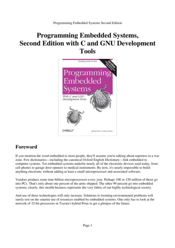
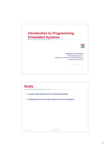
Chapter 2: Microcontrollers and the PIC16F8772.0 Chapter SummarySection 2.1 covers the types of memories used in the general sense and theirorganization with respect to the data and addressing. Section 2.2 discusses the memoriesused in the PIC. Section 2.3 introduces the most fundamental elements of programmingat the assembly language level.2.1 Memory and Memory OrganizationA microcontroller is a complete computer system on a single chip. It is more thanjust a microprocessor: It also contains a Read-Only Memory (ROM), a Read-WriteMemory (RAM), some input/output ports, and some peripherals, such as,counters/timers, analog-to-digital converters, digital-to-analog converters, and serialcommunication ports.The internal view of a typical microprocessor is shown in Figure 2-1 and iscomposed of three things: an arithmetic/logic unit (ALU) which performs calculations ondata; a set of registers which hold the user’s data and the system’s data; and a control unitwhich orchestrates everything and interprets and executes the user’s instructions. As faras the microprocessor is concerned, it assumes that there are sets of data memories andprogram memories (RAM and ROM) in the system. The only thing the microprocessorhas to do is run a cycle of getting new instructions and executing them from thememories.Both the RAM and the ROM are organized as indexed sets of data words, whereeach “index” is the “address” of its corresponding data. Both the data and its addresscodes are numbers represented in binary or hexadecimal.The RAM is a read-write memory which can rapidly read and write the data. It isa volatile memory which means that it loses its memory when power is removed (turnedoff). The ROM is for program memory and is “read-only” except in modern variants,such as Electrically Erasable Programmable Read Only Memory (EEPROM) and FlashMemory, which allow data words to be written as well as read. The writing of anEEPROM is not the same as a RAM since the data-writing time of the EEPROM is aboutten thousand times as long as the data-writing time of the RAM. The ROM and itsvariants are non-volatile memories that preserve their memories when the power isremoved (turned off).15
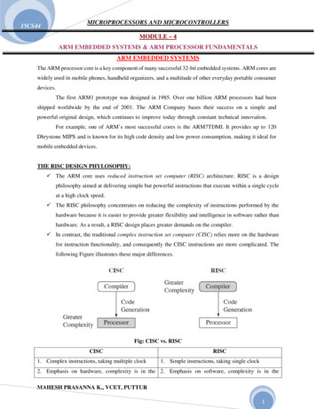
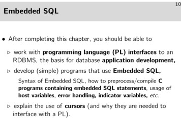
RegistersALUMicroprocessorData BusAddress BusTo / FromSystemMemoryTo AddressSystemMemoryControlUnitFigure 2-1uP Internal ViewBlock Diagram2.2 The PIC16F877The PIC16F877 s internal block diagram is shown in Figure 2-2. The PICcontains an ALU, which does arithmetic and logic operations, the RAM, which is alsocalled the “register-file”, the program EEPROM (Flash Memory), the data EEPROM, andthe “W” register. The “W” register is not a part of the register-file but is a stand-alone,working register (also called an “accumulator”).The ALU, the RAM, the “W” register, and the data EEPROM each manipulateand hold 8-bit-wide data, which ranges in value from zero to 255 (or, in hexadecimal,from 0x00 to 0xFF).The program EEPROM (Flash Memory) works with 14-bit-wide words andcontains each of the user’s instructions.It is not uncommon for microcontrollers to have different sizes of data memoryand program memory (in the PIC: 8-bits for data and 14-bits for program words). Morethan that, the key is that the data and program memories occupy separate spaces. Thisallows access to each at the same time.16
RAMALU128128128 128Bytes Bytes Bytes BytesW RegisterProgramEEPROM8192Words(14-Bits Long)0Timing &Control1234- BanksDataEEPROM256 BytesIn / Out Ports &Other PeripheralsFigure 2-2 PIC16F877 Internal Block DiagramThe PIC’s RAM addresses range from zero to 511 but the user can only access aRAM byte in a set of four “banks” of 128 bytes each and only one bank at a time. Not allof this RAM is available to the user as read-write memory, however. Many addresses arededicated to special functions within the processor but they “look-like” RAM and areaccessed the same way.The PIC’s program EEPROM (Flash Memory) has addresses that range from zeroto 8191 (0x1FFF). The user’s program occupies this memory space.2.3Programming The PICAll types of computer programs can be broken-down into four main sets ofactions:1)2)3)4)Top-Down ExecutionConditional BranchingLoopsSubroutine Calls17
Programming the PIC in assembly language is no exception but it is more difficult towork with than high-level languages, like BASIC and C .Assembly language uses a one-to-one correspondence of mnemonic words withthe binary machine codes that the processor uses to code the instructions. The user writesthe program using the mnemonic words called the “source” program and gives this to theprogram on the PC called the “assembler” which converts it into the machine code of thePIC in the form of a list of hexadecimal numbers. This set of numbers is called the“object” program. The user then writes the object program into the PIC in thedownloading process of programming the PIC. When this is done, the PIC is ready to runits new program.Understanding how to code a program in assembly language is contingent uponunderstanding how the PIC works at the machine level.The PIC executes instructions from program memory in sequential addresses,starting from address zero, when the PIC is reset upon power-up. The address of thecurrent instruction being executed is given in a special register called, the “programcounter” (PC). The PIC’s control unit automatically increments the program-counter(PC), gets the next instruction, decodes that instruction, and then executes it. If this isdone on sequential addresses, this is called, “top-down” execution. There are also waysto do non-sequential-address executions. This is done with special instructions whichload new addresses into the program-counter. This is how conditional-branching, loops,and subroutines are done at the machine language level.Each line of source program code in assembly language has up to four parts: Alabel, an op-code, an operand, and a comment. This is shown as follows:LABEL:OPCODE OPERAND(S); COMMENTThe label is an arbitrary name the user picks to mark a program address, a RAM address,or a constant value. If the label has its first character (a letter) that starts in column one ofthe text, the colon is optional. Otherwise, the colon separates the label from the “OpCode”. The “Op-Code” is short for, “Operation-Code”, and is the mnemonic name forthe instruction to be executed. The operand or operands are the data or the address thatthe instruction uses when it is to be executed. This is where labels come into play such aswhen an instruction needs a new address. Comments are optional and must begin with asemi-colon. Comments are for documenting the source program so that it will be easy toread and understand. For example, the following lines are valid source program codelines:18
LOOP:BSFFLAGS,2; Set Alarm Flag BitMAIN:CALLSORT SUB; Sort the DataDECFSZTEMP,F; This is an example of a line which consists of only a commentMAINCALLSORT SUB ; Sort the Data (No Colon in Label)19
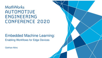
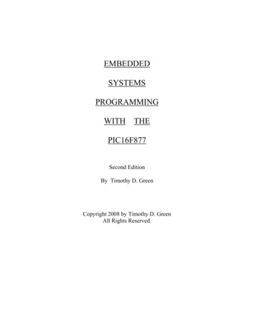
Chapter 3: Simple PIC Hardware& Software (“Hello World”)3.0Chapter SummarySection 3.1 introduces a simple PIC system and analyzes its controlling program.It looks at each instruction, examines its structure and coding, and sets a foundation forproper usage of assembly language. Section 3.2 summarizes the instructions andconcepts covered in Section 3.1.3.1 A Simple Example SystemAn external view of the PIC with its pins is shown in Figure 3-1. This is the mostbasic view of the PIC’s functions. Most pins have a second use, or, even a third use: torun the PIC’s peripherals, such as the ADC, the timers, and the serial ports, to name afew. These other functions will be shown later as they are needed.The basic function of these pins is for digital inputs and digital outputs. Theindividual bits on each of the input/output ports (A-through-E) can each be selected as“input” or “output” by special configuration registers in the RAM. The software must setthese bits before the ports can be used. This will be shown in more detail shortly.An example circuit which uses the input/output (I/O) ports “B” and “C” is shownin Figure 3-2. This is a simple, bare minimum, PIC example circuit that serves tointroduce some simple software and instructions. Port “B” has a set of 8 DIP switcheswith resistor pull-ups on it to allow data from these switches to be read into the PIC. Port“C” drives a set of 8 LEDs through resistors to allow the PIC to send out and display itsdata. The power supply must drive both sets of power pins as shown in Figure 3-2. Theclock input, OSC1, is driven by an external oscillator module as shown. Also, a 10KOhm pull-up resistor is used on Pin 1 (/MCLR) to keep the PIC out of its “Reset” state.The following program can be used to run the circuit of Figure 3-2:LIST P 16F877INCLUDE “P16F877.INC”ORGNOPBANKSELMOVLWMOVWF0x0000; Program starts at address zero.PORTC; Select Bank ZeroB’00000000’ ; Reset PORTCPORTC20
0’TRISCB’11111111’TRISBPORTC; Select Bank One; Make PORTC All OutputsMOVFMOVWFGOTOENDPORTB,WPORTCMAIN; Read DIP Switches into W-Register; Write W-Register to LEDs; Loop To Address “MAIN”; Make PORTB All Inputs; Select Bank ZeroMAIN:/MCLR or VppPORT 19RE210Vdd 5 Volts11Vss Ground12OSC113OSC2RC0PORT EPORT CLow HalfPORT DLow HalfRB71RA0PIC16F877PORT B35RB234RB133RB032Vdd 5 Volts31Vss 24RC5RC31823RC4RD019RD120PORT DHigh HalfPORT CHigh Half22RD3PORT D21RD2Low HalfFigure 3-1 Simple Hardware View (Ports Only)After setting up Port “C” as an “output” and Port “B” as an “input”, this programreads the value of the switches on Port “B” and sends it back out to the LEDs on Port “C”in a continuous loop. This may seem like a very trivial progr
4-1 A Simple Security System 5-1 Twelve-Key Matrix Keypad . 7-1 Gaussian Probability Density Function and a Set of Sampled Values . 8-2 PIC16F877 Interrupt Tree 9-1 Master Mode SPI Mode Timing 9-2 Serial-Out/Serial-In with the 74HC164 and 74HC165 9-3 Serial-Out/Serial-In with Gated Clock