Transcription
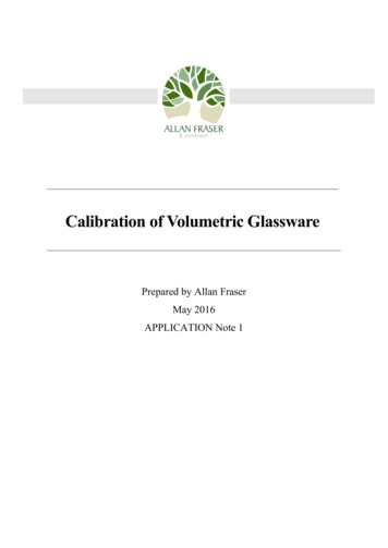
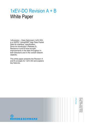
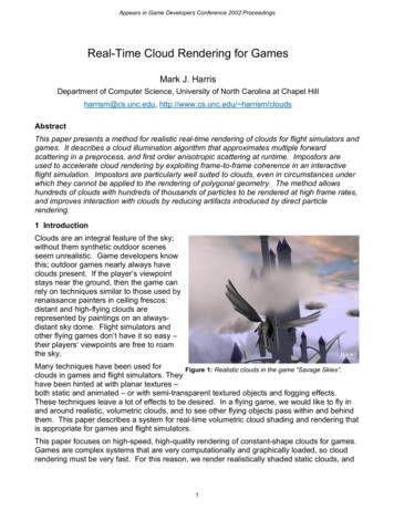
Real-Time Volumetric RenderingBy Patapom / Bomb! (spring 2013, course notes for the Revision Demo Party)Almost everyone in the demoscene is enjoying ray-marching through a distance field but Ihaven’t seen much volumetric rendering done with it.So, why not use ray-marching to achieve what it was created for originally: rendering aparticipating medium?What’s a participating medium? It’s a volume (the medium) where refraction, density and/or albedo changes locallyAll medium is in fact a participating medium at some level; it all depends on the distanceswe’re considering. But some media can be thought of as “homogeneous” on short distances.Homogeneous Medium (air, water, glass) on short distances:In most cases though, we have to consider a heterogeneous medium with characteristics thatvary more or less quickly.What can happen to a flux of photons when we make these qualities change?
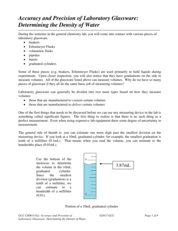
Absorption, which may change according to wavelength, like we see here: a blue coloringoccurs after long distances in water.Scattering; photons are bouncing off of particles in various directions.Depending on the density and type of particles, scattering is more or less random, more or lessfrequent.To sum up, what happens to a flux of photons is one of these events:
(I’ll come back later to a last type of event: emission)Scattering & ExtinctionConsider a single particle (molecule, dust, a water droplet or whatever):Photons are going to interact with it and bounce off of its “surface”.In the case of clouds, imagine a single microscopic water droplet: the droplet will either refractor reflect the rays of light, but almost none of them will be absorbed; this is why clouds are sobright: their albedo (ratio of reflected over incoming light) is nearly 100%.What happens if light is traveling in a volume filled with a large density of such particles?In the end, it’s a game of chance: what is the chance I hit a particle after N meters?Particle Cross-Sectionis the effective radius (typical radius for water droplets in a cloud)Absorption/Scattering Cross-Sectionis the density of droplets (for clouds, depending on the type and air pollution, from)(it also gives us typical values ofare then)NOTE: When the light hits a particle we saw it could be absorbed or scattered.The net effect is loss of energy (extinction), this is why inis really the sum of 2 coefficients:Extinction coefficientWhereis the Absorption coefficient andis the Scattering coefficient.
ExtinctionNow, here’s one of the most important equations for rendering a participating medium: theExtinction Function also known as the Beer-Lambert law.This represents the probability to traverse the medium along a path of length d without hittinga particle. And incidentally, this also represents the transparency of the medium!So, any radiance at distanceentering the cloud will see its intensity decrease:Here, represents the view direction, is the position where the light exits the volume (the“Out”, in the figure) andis the distance between In and Out (sois point “In” in theabove figure).Notice that and are written using a boldface font to mark the fact they are 3D vectors.Other quantities are scalars.NOTE: Equationis homogeneous).can be considered valid as long asis supposed constant (i.e. as long as we agree a mediumIn-ScatteringSo all right, we lose energy as we bump our way through molecules and particles. But there isalso energy coming from somewhere else that may bump off in the direction we are viewingonce again!That would indeed add some energy and maybe even compensate the loss by extinction(imagine a magnifying glass bending light rays and concentrating energy onto a single spot).
Now, we need to estimate the chance for light to bounce from one particular direction off toanother. Preferably, the direction we’re looking at.The Phase FunctionIt’s almost the same as a BRDF for materials: A black box indicating how light is interacting with the material Difference with the BRDF is that it usually considers a single angle (the phase anglebetween 2 directions) and integrates to 1 over the entire sphere of directions. ̂̂ is the angle between incoming and outgoing directions andWhereof all possible directions.represents the sphere The “average cosine” of the phase function gives us , the preferred scattering directionwhich will vary between -1 (backward scattering, light will be reflected back toward thesource) to 1 (forward scattering, light will continue unaffected) There exist some simple analytical models of phase functions.Rayleigh Phase FunctionWhen the considered particles are small enough, Rayleigh scattering is occurring. The phasefunction is peanut-shaped:
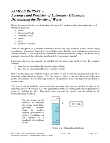
The importance of scattering by molecules whose size is the same order of magnitude as thelight’s wavelength is proportional to the reciprocal of the wavelength’s 4th power:Meaning that scattering atistimes as great as that at. This is the mainreason why the sky is blue: shorter wavelengths (blue) are more scattered than longwavelengths (red).Henyey-Greenstein Phase FunctionFor larger particles like pollutants, aerosols, dust and water droplets we must use Miescattering.Mie theory of scattering is very difficult to apprehend and the variety and complexity in shapeand behaviors of the various components of the atmosphere usually make phase functions verydifficult to work with.For example, here is what the average statistical phase function of a cloud would look like:Instead of using that complex phase function, we usually choose a composition of multiplesimpler functions called “Henyey-Greenstein” phase functions that look like this:
We findagain, the preferred scattering direction that can vary in.NOTE: Because of the exponent the HG phase function is often replaced by the much cheaper Schlick phasefunction:How to use them?First, we must underline the fact that we’re going to use phase functions only for singlescattering events: light that bounces only once off a particle. Multiple scattering events arevery expensive and will be approximated another way as we will see later.Phase functions can be cumulated using weights, assuming the sum of the weights is 1: So, in order to represent the complex Mie scattering from the figure above, we can simply use aweighted sum of simpler phase functions.
What about we start coding all this?Armed with all the necessary knowledge, we must now focus on the code.First of all, here are the equations we’re dealing with: ()[ ] is the radiance at distance x (not a vector here!) along the directiondistance we need to trace inside the medium.andis the The part in green is the extinction we saw earlier. It uses a new quantity, in brown,called the Optical Depth which represents the accumulated extinction coefficientsalong the path from x to x’, multiplied by the length of that path.It simplifies nicely intoif is supposed constant along a path oflengthbut for this to work, we’ll have to split the trace into small path (we’ll cometo that later). The part in blue is the in-scattering. We retrieve the phase function and a complexintegral of lightcoming from all possible directions (rememberis thesphere of all possible directions).The tricky part here is this:needs to be itself computed using equation (4)!It’s a recursive relation, and each level of recursion accounts for a new order ofscattering event.And this is the main reason why multiple scattering is very expensive and why weapproximate it using a simple ambient term most of the time.(Note: this part is the equivalent of indirect lighting when performing global illumination)
In the figure above from [3], Bouthors et al. have taken into account scattering events up toorder 20 (!!) and explain they are still relevant to the correct appearance of clouds!This image is also the result of a compacting of a 25GB database computed in 7 days. So we canforget about it already! Let’s SimplifyFirst of all, we split light sources into 3 categories: Direct Lighting from the SunIndirect Lighting from the SunIndirect Lighting from the SkyEquation (4) then becomes: ()It’s a little prettier without the inner integral. We brought back the complexity into our abilityto determine a nice value for.This integral can be read as:1) Compute incoming light arriving at x’ from the Sun and ambient environment2) Scatter it using
3) Let the viewer perceive only a small part of that light because of extinction between xand x’4) Start again for the next small stepWe can easily discretize the integral into this new equation: Withand N the amount of discrete steps we take inside the medium.Now, to get rid of the annoying part in green we can notice that:(Applying this recursively with our fixed steps)()we get: We see it becomes an accumulation of opacity in the form of a product of the opacities of eachsmall slice. Easily something we could keep in a register on the side, and multiply with at eachnew step.The final equations for our shader thus becomes:
The Shader CodeHere is the shader pseudo code for our ray marcher:float3 Position Start position at the beginning of the volume;float3 View Our normalized view direction;float Extinction 1.0; // We start with full transparencyfloat3 Scattering 0.0; // We start with no accumulated lightfor each step{float Density SampleMediumDensity( Position ); // Sample a noise of some sort. Returns [0,1]float ScatteringCoeff ScatteringFactor * Density;float ExtinctionCoeff ExtinctionFactor * Density;// Accumulate extinction for that stepExtinction * exp( -ExtinctionCoeff * StepSize );// Compute in-scattered lightfloat3 SunColor ComputeSunColor( Position ); // Get Sun color arriving at positionfloat3 AmbientColor ComputeAmbientColor( Position, ExtinctionCoeff ); // Get ambient color at positionfloat3 StepScattering ScatteringCoeff * StepSize * (PhaseSun * SunColor PhaseAmbient * AmbientColor);Scattering Extinction * StepScattering; // Accumulate scattering attenuated by extinction// March forwardPosition StepSize * View;}return float4( Scattering, Extinction );Notice that we return a float4 containing an alpha. But also notice that all along the raymarching process we composed our scattered light color with a part of this alpha (the“Extinction * StepScattering” line).We have a color pre-multiplied by its alpha, and thus the composition of that color with abackground must use the pre-multiplied alpha blending operation [5]:NOTE: In that example, we restricted ourselves by computing a monochromatic extinction stored as a single floatbut some events like Rayleigh scattering are actually wavelength dependent and in that case we must also considerthe extinction as a float3 which will address the RGB components of the destination background (i.e. masking itwith coloring).We can no longer store a single Alpha value and thus need to use multiple render targets.The Missing PartsWe’re now left with some missing parts of the algorithm:
SampleMediumDensity( pos ), that computes the density of the medium at the given positionComputeSunColor( pos ), that computes the lighting by the Sun at the given positionComputeAmbientColor( pos ), that computes the ambient lighting at the given positionComputing the DensityWell this part is quite easy to implement as a Fractional Brownian Motion noise type that iswell known to the demoscene (I’ve tried multiple types of noise (cellular, turbulence, ridgedmultifractal, etc.) and that’s by far the best one for realistic clouds rendering).static const float AMPLITUDE FACTOR 0.707f;// Decrease amplitude by each new octavestatic const float FREQUENCY FACTOR 2.5789f; // Increase frequency by some factor each new octavefloat SampleMediumDensity( float3 Position ){float3 UVW Position * 0.01; // Let’s start with some low frequencyfloat Amplitude 1.0;float V Amplitude * Noise( UVW ); Amplitude * AMPLITUDE FACTOR; UVW * FREQUENCY FACTOR;V Amplitude * Noise( UVW ); Amplitude * AMPLITUDE FACTOR; UVW * FREQUENCY FACTOR;V Amplitude * Noise( UVW ); Amplitude * AMPLITUDE FACTOR; UVW * FREQUENCY FACTOR;V Amplitude * Noise( UVW ); Amplitude * AMPLITUDE FACTOR; UVW * FREQUENCY FACTOR;// Repeat as many times as necessary return clamp( DensityFactor * V DensityBias, 0, 1 ); // Factor and bias to help getting a nice result }This part is essential and also very important to keep fast so I would advise to pack all thenoise octaves in a large 3D texture but not too large either to avoid flushing your cache by toomuch tiling. To avoid obvious tiling the best I found is to use a low frequency 3D texture(something like) tiling veeery slowly to which you add detail with a larger 3D texture(something like) that tiles faster.Computing the Sun’s colorI left a big disappointment for the end! The algorithm is not that simple after all: we need someshadowing in our volume.If we use a constant value for the light, not accounting for the sampling position within thevolume, then the cloud will look quite unrealistic. Self-shadowing is of the utmost importance.That means we need a shadow map, and one that stores volumetric shadowing at that!Several techniques exist: Deep Shadow Maps [6]o Not GPU friendly, we need to manage lists and perform sortingo Now possible with DX11 UAVs but not optimal Opacity Shadow Maps [7]o Store Z where opacity reaches specified levelso Lacks precision Transmittance Function Maps [8]
ooCompact transmittance function using DCT basisNice precision using only 6 coefficients ZMin/ZMax stored into 2 rendertargetsIn any case, we also need to ray-march the volume from the light’s point of view.The shader code that will create the shadow map should be the same as our ray-marcherbefore except that: This time we ray-march from the point of view of the light, not the camera We only account for extinction (or Transmittance) and don’t care about scattering We need to store/compact/encode that extinction at several key points in thevolume, not a single value at the endIn the end, the pseudo-code using the volumetric shadow map is really simple:float3 ComputeSunColor ( float3 Position ){float3 ShadowMapPosition Position * World2ShadowMap; // Transform from world to shadow map spacefloat2 UV ShadowMapPosition.xy; // Our shadow map texture coordinates in [0,1]float Z ShadowMapPosition.z;// Our depth in the shadow volume as seen from the lightfloatExtinction GetShadowExtinction( UV, Z ); // Samples the shadow map and returns extinction in [0,1]return Extinction * SunColor; // Attenuate sun color by extinction through the volume}Computing the Ambient colorThe ambient color is very important to get right because it adds the realism we’re lacking whenconsidering only single scattering.I’ll show you a nice trick of mine that gives quite a nice result.The idea is to think of the medium as an infinite slab of uniform density, the current densityyou sampled earlier in the ray-marching loop, then you assume you receive an ambientlighting from the sky (or the earth if you’re considering the bottom slab) and the Sun that you“made ambient” by dividing its intensity by(think of it as a isotropic phase function) and afactor that concentrates the loss due to high order scattering events.
We assume we have a homogeneous “ambient” radiance shining on our point P coming fromthe hemisphere of all possible directions that we will callfor lighting from the top, andfor lighting from the bottom.For isotropic lighting from top, we get : Where :is the top radianceis the top hemisphere of all possible directionsis the isotropic phase function (another assumption)is the local normal to the volume, pointing upThere is obviously a similar equation for the bottom part of the slab by replacing the subscripts with the - sign.Factoring out the constant terms and rewriting as a double integral over the hemisphere inspherical coordinates, we get:
WithFortunately, the integral has a closed form solution: Where[]is the exponential integral.So here you go merrily with the pseudo-code:// Exponential Integral// (http://en.wikipedia.org/wiki/Exponential integral)float Ei( float z ){return 0.5772156649015328606065 log( 1e-4 abs(z) ) z * (1.0 z * (0.25 z * ( (1.0/18.0) z * ( (1.0/96.0) z *(1.0/600.0) ) ) ) ); // For x! 0}float3 ComputeAmbientColor ( float3 Position, float ExtinctionCoeff ){float Hp VolumeTop - Position.y; // Height to the top of the volumefloat a - ExtinctionCoeff * Hp;float3 IsotropicScatteringTop IsotropicLightTop * max( 0.0, exp( a ) - a * Ei( a ));float Hb Position.y - VolumeBottom; // Height to the bottom of the volumea - ExtinctionCoeff * Hb;float3 IsotropicScatteringBottom IsotropicLightBottom * max( 0.0, exp( a ) - a * Ei( a ));return IsotropicScatteringTop IsotropicScatteringBottom;}Values for IsotropicLightTop are coming from the Sky and “Sun made ambient”, values forIsotropicLightBottom can also add the contribution of Sun light that bounced off the groundso you can simulate color bleeding.
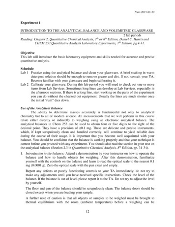
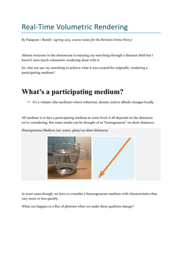
We can see the improvement here:Bonus: Emissive MediumOn top of absorption and scattering events, you could also assume your medium is emittingsome light (explosion, flame, etc.).This is really easy to add to your ray-marching loop if you simply add an emissive term to theStepScattering variable.This term could be linked to the temperature of the medium (black body radiation) or dependon a light source lying in the medium.ConclusionAs a summary, the steps you need to take to render a participating medium are:1) Render a shadow map with volumetric information about extinction This requires to ray-march the volume from the light’s point of view2) Render the volume by ray-marching Accumulate lighting by querying the volumetric shadow map Perform extinction along the ray3) Compose the resulting image (Scattering Extinction) with the background using thepre-multiplied alpha blend modeTypically, a minimum of 16 steps of ray-marching are necessary to render the shadow mapwhile 64 or more steps may be needed to render the volume itself, depending on the level ofdetail you wish to attain.
Nowadays, one can easily attain several hundreds of frames per second for a fullscreen, welldetailed rendering of an entire sky as it is the case with Nuaj’, my atmosphere renderer forUnity.The physical processes behind extinction and scattering can also be employed to render manyother mediums like water, skin or translucent objects.Hopefully, with a little practice, you will be able to master these new tools and makevolumetric rendering a common practice in the demoscene or game industry.References:[1] “Physics and Math of Shading”, Naty Hoffman. Siggraph 2012[2] “Real-time realistic illumination and shading of stratiform clouds”, Bouthors et al.,Eurographics Workshop on Natural Phenomena - 2006[3] “Interactive multiple anisotropic scattering in clouds”, Bouthors et al., ACM Symposium onInteractive 3D Graphics and Games (I3D) – 2008[4] “Cloud liquid water content, drop sizes, and number of droplets”[5] “Pre-Multiplied Alpha”, Tom Forsyth - 2006[6] “Deep Shadow Maps”, Lokovic & Veach - 2000[7] “Opacity Shadow Maps”, Kim & Neumann – 2001[8] “Transmittance Function Mapping”, Delalandre et al., I3D '11 Symposium on Interactive 3DGraphics and Games – 2011
Real-Time Volumetric Rendering By Patapom / Bomb! (spring 2013, course notes for the Revision Demo Party) Almost everyone in the demoscene is enjoying ray-marching through a distance field but I haven’t seen much volumetric rendering done with it. So, why not use ray-marching to achieve what it