Transcription
HomeSearchCollectionsJournalsAboutContact usMy IOPscienceSlowing and stopping light using an optomechanical crystal arrayThis content has been downloaded from IOPscience. Please scroll down to see the full text.2011 New J. Phys. 13 3003)View the table of contents for this issue, or go to the journal homepage for moreDownload details:IP Address: 129.6.136.118This content was downloaded on 27/06/2014 at 14:23Please note that terms and conditions apply.
New Journal of PhysicsThe open–access journal for physicsSlowing and stopping light using an optomechanicalcrystal arrayD E Chang1,4 , A H Safavi-Naeini2,4 , M Hafezi3 and O Painter2,51Institute for Quantum Information and Center for the Physics of Information,California Institute of Technology, Pasadena, CA 91125, USA2Thomas J Watson, Sr, Laboratory of Applied Physics, California Institute ofTechnology, Pasadena, CA 91125, USA3Joint Quantum Institute and Department of Physics, University of Maryland,College Park, MD 20742, USAE-mail: opainter@caltech.eduNew Journal of Physics 13 (2011) 023003 (26pp)Received 24 November 2010Published 1 February 2011Online at 03One of the major advances needed to realize all-optical informationprocessing of light is the ability to delay or coherently store and retrieve opticalinformation in a rapidly tunable manner. In the classical domain, this opticalbuffering is expected to be a key ingredient of managing the flow of informationover complex optical networks. Such a system also has profound implications forquantum information processing, serving as a long-term memory that can storethe full quantum information contained in an optical pulse. Here, we suggest anovel approach to light storage involving an optical waveguide coupled to anoptomechanical crystal array, where light in the waveguide can be dynamicallyand coherently transferred into long-lived mechanical vibrations of the array.Under realistic conditions, this system is capable of achieving large bandwidthsand storage/delay times in a compact, on-chip platform.Abstract.45These authors contributed equally to this work.Author to whom any correspondence should be addressed.New Journal of Physics 13 (2011) 0230031367-2630/11/023003 26 33.00 IOP Publishing Ltd and Deutsche Physikalische Gesellschaft
2Contents1. Introduction2. Description of the system: an optomechanical crystal (OMC) array3. Slowing and stopping light3.1. Static regime . . . . . . . . . . . . . . . . . . . . . . . . . . . . . . . . . . .3.2. Storage of optical pulse . . . . . . . . . . . . . . . . . . . . . . . . . . . . . .3.3. Imperfections in storage . . . . . . . . . . . . . . . . . . . . . . . . . . . . .4. OMC design5. OutlookAcknowledgmentsAppendix A. Equations of motion for an OMC arrayAppendix B. Transfer matrix analysis of propagationAppendix C. Optical noise powerAppendix D. The band structure analysisAppendix E. Implementation in an OMCReferences2355891013131315161720241. IntroductionLight is a natural candidate for transmitting information across large networks owing to its highspeed and low propagation losses. A major obstacle to building more advanced optical networksis the lack of an all-optically controlled device that can robustly delay or store optical wavepackets over a tunable amount of time. In the classical domain, such a device would enable alloptical buffering and switching, bypassing the need to convert an optical pulse to an electronicsignal. In the quantum realm, such a device could serve as a memory to store the full quantuminformation contained in a light pulse until it can be passed to a processing node at somelater time.A number of schemes to coherently delay and store optical information are beingactively explored. These range from tunable coupled resonator optical waveguide (CROW)structures [1, 2], where the propagation of light is dynamically altered by modulating therefractive index of the system, to electromagnetically induced transparency (EIT) in atomicmedia [3, 4], where the optical pulse is reversibly mapped into internal atomic degreesof freedom. While these schemes have been demonstrated in a number of remarkableexperiments [5]–[8], they remain difficult to implement in a practical setting. Here, we presenta novel approach to store or stop an optical pulse propagating through a waveguide, whereincoupling between the waveguide and a nearby nanomechanical resonator array enables one tomap the optical field into long-lived mechanical excitations. This process is completely quantumcoherent and allows the delay and release of pulses to be rapidly and all-optically tuned. Ourscheme combines many of the best attributes of previously proposed approaches, in that itsimultaneously allows for large bandwidths of operation, on-chip integration, relatively longdelay/storage times and ease of external control. Beyond light storage, this work opens up theintriguing possibility of a platform for quantum or classical all-optical information processingusing mechanical systems.New Journal of Physics 13 (2011) 023003 (http://www.njp.org/)
32. Description of the system: an optomechanical crystal (OMC) arrayAn optomechanical crystal (OMC) [9] is a periodic structure that comprises both a photonic [10]and a phononic [11] crystal. The ability to engineer optical and mechanical properties in thesame structure should enable unprecedented control over light–matter interactions. Planar twodimensional (2D) photonic crystals, formed from patterned thin dielectric films on the surface ofa microchip, have been succesfully employed as nanoscale optical circuits capable of efficientlyrouting, diffracting and trapping light. Fabrication techniques for such 2D photonic crystals havematured significantly over the last decade, with experiments on an Si chip [12] demonstratingexcellent optical transmission through long (N 100) linear arrays of coupled photonic crystalcavities. In a similar Si chip platform, it has recently been shown that suitably designed photoniccrystal cavities also contain localized acoustic resonances that are strongly coupled to theoptical field via radiation pressure [9]. These planar OMCs are thus a natural candidate forthe implementation of our proposed slow-light scheme.In the following, we consider an OMC containing a periodic array of such defect cavities(see figures 1(a) and (b)). Each element of the array contains two optical cavity modes (denoted1, 2) and a co-localized mechanical resonance. The Hamiltonian describing the dynamics of asingle element is of the formH̃ om h̄ω1 â †1 â 1 h̄ω2 â †2 â 2 h̄ωm b̂† b̂ h̄h(b̂ b̂† )(â †1 â 2 â †2 â 1 ).(1)Here, ω1,2 are the resonance frequencies of the two optical modes, ωm is the mechanicalresonance frequency and â 1 , â 2 , b̂ are annihilation operators for these modes. Theoptomechanical interaction cross-couples the cavity modes 1 and 2 with a strength characterizedby h and that depends linearly on the mechanical displacement x̂ (b̂ b̂† ). While we formallytreat â 1 , â 2 , b̂ as quantum mechanical operators, for the most part it also suffices to treat theseterms as dimensionless classical quantities describing the positive-frequency components of theoptical fields and mechanical position. In addition to the optomechanical interaction describedby equation (1), cavity modes 1 are coupled to a common two-way waveguide (describedbelow). Each element is decoupled from the others except through the waveguide.The design considerations necessary for achieving such a system are discussed in detail inthe section ‘Optomechanical crystal design’. For now, we take as typical parameters ω1 /2π 200 THz, ωm /2π 10 GHz, h/2π 0.35 MHz and mechanical and (unloaded) optical qualityfactors of Q m ωm /γm 103 (room temperature)–105 (low temperature) and Q 1 ω1 /κ1,in 3 106 , where γm is the mechanical decay rate and κ1,in is the intrinsic optical cavity decayrate. Similar parameters have been experimentally observed in other OMC systems [9, 13]. Inpractice, one can also over-couple cavity mode 1 to the waveguide, with a waveguide-inducedoptical decay rate κex that is much larger than κin .For the purpose of slowing light, cavity modes 2 will be resonantly driven by an externallaser, so that to good approximation â 2 α2 (t)e iω2 t can be replaced by its mean-field value. Wefurthermore consider the case where the frequencies are tuned such that ω1 ω2 ωm . Keepingonly the resonant terms in the optomechanical interaction, we arrive at a simplified Hamiltonianfor a single array element (see figure 1(b)),Hom h̄ω1 â †1 â 1 h̄ωm b̂† b̂ h̄ m (t)(â †1 b̂ e i(ω1 ωm )t h.c.).(2)Here, we have defined an effective optomechanical driving amplitude m (t) hα2 (t) andassume that α2 (t) is real. Mode 2 thus serves as a ‘tuning’ cavity that mediates populationNew Journal of Physics 13 (2011) 023003 (http://www.njp.org/)
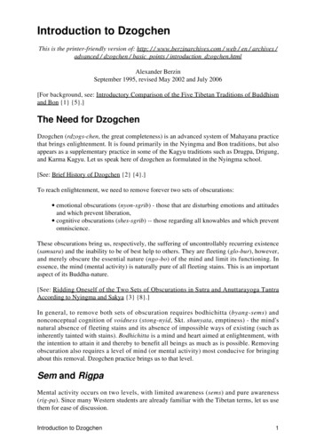
4(a)(b)opticalwaveguideaR (z)aL (z)exexa1a2hininbaR (z d)aR (z)aL (z d)aL (z)opticalwaveguideaR (z d)exopticalcavitiesaL (z mechanicalcavitybmm10.9(d)(c)0.8 nm , n 1 110.7 t 2, Ω 0 r 2, Ω 0 t 2, Ω κ/10 r 2, Ω κ/100.60.50.40.5aR (z,t) m(t)0.30.200.1-0.100.10-3-2-1012 nm , n 1 nm 1, n 1 3δ/κFigure 1. (a) Illustration of a double optical cavity system forming the unitcell of the optomechanical array. A two-way optical waveguide is coupled toa pair of optical cavity modes a1 and a2 , whose resonance frequencies differby the frequency of the mechanical mode b. Both optical modes leak energyinto the waveguide at a rate κex and have an inherent decay rate κin . Themechanical resonator optomechanically couples the two optical resonances witha cross-coupling rate of h. (b) A simplified system diagram where the classicallydriven cavity mode a2 is effectively eliminated to yield an optomechanicaldriving amplitude m between the mechanical mode and the cavity mode a1 .(c) Frequency-dependent reflectance (black curve) and transmittance (red) ofa single array element, in the case of no optomechanical driving amplitude m 0 (dotted line) and an amplitude of m κex /10 (solid line). The inherentcavity decay is chosen to be κin 0.1κex . (Inset) The optomechanical couplingcreates a transparency window of width 4 2m /κex for a single element andenables perfect transmission on resonance, δk 0. (d) Energy level structureof the simplified system. The number of photons and phonons are denoted byn 1 and n m , respectively. The optomechanical driving amplitude m couplesstates n m 1, n 1 i n m , n 1 1i, while the light in the waveguide couples states n m , n 1 i n m , n 1 1i. The two couplings create a set of 3-type transitionsanalogous to that in EIT.New Journal of Physics 13 (2011) 023003 (http://www.njp.org/)
5transfer (Rabi oscillations) between the ‘active’ cavity mode 1 and the mechanical resonatorat a controllable rate (t), which is the key mechanism for our stopped-light protocol. Inthe following analysis, we will focus exclusively on the active cavity mode and drop the ‘1’subscript.A Hamiltonian of the form (2) also describes an optomechanical system with asingle optical mode, when the cavity is driven off resonance at frequency ω1 ωm and â 1corresponds to the sidebands generated at frequencies ωm around the classical driving field.For a single system, this Hamiltonian leads to efficient optical cooling of the mechanicalmotion [14, 15], a technique being used to cool nanomechanical systems toward their quantumground states [16]–[19]. While the majority of such work focuses on how optical fieldsaffect the mechanical dynamics, here we show that the optomechanical interaction stronglymodifies optical field propagation to yield the slow/stopped light phenomenon. Equation (2)is quite general and thus this phenomenon could, in principle, be observed in any array ofoptomechanical systems coupled to a waveguide. In practice, there are several considerationsthat make the 2D OMC ‘ideal’. Firstly, our system exhibits an extremely large optomechanicalcoupling h and contains a second optical tuning cavity that can be driven resonantly, whichenables large driving amplitudes m using reasonable input power [20]. Using two differentcavities also potentially allows for greater versatility and addressability of our system. Forinstance, in our proposed design the photons in cavity 1 are spatially filtered from those in cavity2 [20]. Secondly, the 2D OMC is an easily scalable and compact platform. Finally, as describedbelow, the high mechanical frequency of our device compared to typical optomechanicalsystems allows for a good balance between long storage times and suppression of noiseprocesses.3. Slowing and stopping light3.1. Static regimeWe first analyze propagation in the waveguide when m (t) m is static during the transitinterval of the signal pulse. As shown in the appendix, the evolution equations in a rotatingframe for a single element located at position z j along the waveguide are given byr dâκcκex â i m b̂ i(â R,in (z j ) â L,in (z j )) cκin â N (z j ),(3)dt22db̂γm b̂ i m â F̂ N (t).dt2(4)Equation (3) is a standard input relation characterizing the coupling of right- (â R,in ) and leftpropagating (â L,in ) optical input fields in the waveguide with the cavity mode. Here κ κex κinis the total optical cavity decay rate, â N (z) is quantum noise associated with the inherent opticalcavity loss, and for simplicity we have assumed a linear dispersion relation ωk c k in thewaveguide. Equation (4) describes the optically driven mechanical motion, which decays at arate γm and is subject to thermal noise F̂ N (t). The cavity mode couples to the right-propagatingfield through the equationr 1 κex â R (z, t) iδ(z z j )â ik0 â R ,(5)c t z2cNew Journal of Physics 13 (2011) 023003 (http://www.njp.org/)
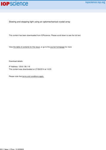
6where k0 ω1 /c. We solve the above equations to find the reflection and transmissioncoefficients r, t of a single element for a right-propagating incoming field of frequency ωk (seethe appendix). In the limit where γm 0, and defining δk ωk ω1 ,r (δk ) δk κex,δk ( 2iδk κ) 2i 2m(6)while t 1 r . Example reflectance and transmittance curves are plotted in figure 1(c). Forany non-zero m , a single element is perfectly transmitting on resonance, whereas for m 0resonant transmission past the cavity is blocked. When m 6 0, excitation of the cavity mode isinhibited through destructive interference between the incoming field and the optomechanicalcoupling. In EIT, a similar effect occurs via interference between two electronic transitions. Thisanalogy is further elucidated by considering the level structure of our optomechanical system(figure 1(d)), where the interference pathways and the ‘3’-type transition reminiscent of EITare clearly visible. The interference is accompanied by a steep phase variation in the transmittedfield around resonance, which can result in a slow group velocity. These steep features andtheir similarity to EIT in a single optomechanical system have been theoretically [21, 22] andexperimentally studied [23, 24], while interference effects between a single cavity mode andtwo mechanical modes have also been observed [25].From r, t for a single element, the propagation characteristics through an infinite array(figure 2(a)) can be readily obtained via band structure calculations [10]. To maximize thepropagation bandwidth of the system, we choose the spacing d between elements such thatk0 d (2n 1)π/2 where n is a non-negative integer. With this choice of phasing, the reflectionsfrom multiple elements destructively interfere under optomechanical driving. Typical bandstructures are illustrated in figures 2(b)–(f). The color coding of the dispersion curves (red forwaveguide, green for optical cavity and blue for mechanical resonance) indicates the distributionof energy or fractional occupation in the various degrees of freedom of the system in steadystate. Far away from the cavity resonance, the dispersion relation is nearly linear and simplyreflects the character of the input optical waveguide, while the propagation is strongly modifiednear resonance (ω ω1 ω2 ωm ). In the absence of optomechanical coupling ( m 0), atransmission band gap of width κ forms around the optical cavity resonance (reflections fromthe bare optical cavity elements constructively interfere). In the presence of optomechanicaldriving, the band gap splits in two (blue shaded regions) and a new propagation band centeredon the cavity resonance appears in the middle of the band gap. For weak driving ( m . κ), thewidth of this band is 4 2m /κ, whereas for strong driving ( m & κ), one recovers the ‘normalmode splitting’ of width 2 m [26]. This relatively flat polaritonic band yields the slow-lightpropagation of interest. Indeed, for small m , the steady-state energy in this band is almostcompletely mechanical in character, indicating the strong mixing and conversion of energy inthe waveguide to mechanical excitations along the array.It can be shown that the Bloch wavevector near resonance is given by (see the appendix)keff k0 3κex δk iκex κin δk2 (2κex 3κex κin2 12κex 2m )δk3 .2d 2m4d 4m24d 6m(7)The group velocity on resonance, vg (dkeff /dδk ) 1 δk 0 2d 2m /κex , can be dramaticallyslowed by an amount that is tunable through the optomechanical coupling strength m . Thequadratic and cubic terms in keff characterize pulse absorption and group velocity dispersion,New Journal of Physics 13 (2011) 023003 (http://www.njp.org/)
7(a)(b)d0.8Ωm 0Ωm κ/4Ωm κ/2Ωm κ0.7exajω (π c / a)a j-10.6a j 1inbjm0.9ω (π c / a)0.8(c)(d)0 0.5 10 0.5 10 0.5 10 0.5 1K (π/d)0.60(e)(f )0.585κ ω/4Ω 40.10.4204004Ωmκ0.3bj 10.21 0.4m(t)bj-120.5 κ0.4000.5K (π/d)1 00.51fraction of excitations00.20.40.6K (π/d)0.81 0 0.2 0.4 0.6 0.8 1fraction of excitationsFigure 2. (a) Illustration of an OMC array. A two-way optical waveguide iscoupled to a periodic array of optomechanical elements spaced by a distance d.The optical cavity modes a j of each element leak energy into the waveguideat a rate κex and have an inherent decay rate κin . The mechanical resonator ofeach element has frequency ωm and is optomechanically coupled to the cavitymode through a tuning cavity (shown in figure 1) with strength m . (b) The bandstructure of the system, for a range of driving strengths between m 0 and m κ. The blue shaded regions indicate band gaps, while the color of the bandselucidates the fractional occupation (red for energy in the optical waveguide,green for the optical cavity and blue for mechanical excitations). The dynamiccompression of the bandwidth is clearly visible as m 0. (c) Band structurefor the case m κ/10 is shown in greater detail. (d) The fractional occupationfor each band in (c) is plotted separately. It can be seen that the polaritonicslow-light band is mostly mechanical in nature, with a small mixing with thewaveguide modes and negligible mixing with the optical cavity mode. Zoom-insof panels (c) and (d) are shown in (e) and (f).New Journal of Physics 13 (2011) 023003 (http://www.njp.org/)
8respectively. In the relevant regimewhere κex κin , κex & m , these effects are negligible 2 2 2m)1/3 2mwithin a bandwidth 1ω min( N κex κin , 2(6π). The second term is the bandwidth overκex N 1/3which certain frequency components of the pulse acquire a π -phase shift relative to others,leading to pulse distortion. This yields a bandwidth–delay product ofp1ωτdelay min( 2N κex /κin , (6π N 2 )1/3 )(8)for static m and negligible mechanical losses. When intrinsic optical cavity losses arenegligible, and if one is not concerned with pulse distortion, light can propagate over the fullbandwidth 4 2m /κ of the slow-light polariton band and the bandwidth–delay product increasesto 1ωτdelay N (see the appendix). On the other hand, we note that if we had operated in aregime where k0 d π n, constructive interference in reflection would limit the bandwidth–delayproduct to 1ωτdelay 1, independent of system size.In the static regime, the bandwidth–delay product obtained here is analogous to CROWsystems [2]. In the case of EIT, a static bandwidth–delay product of 1ωτdelay OD results,where OD is the optical depth of the atomic medium. This product is limited by photonabsorptionand rescattering into other directions, and is analogous to our result 1ωτdelay N κex /κin in the case of large intrinsic cavity linewidth. On the other hand, when κin isnegligible, photons are never lost and reflections can be suppressed by interference. This yieldsan improved scaling 1ωτdelay N 2/3 or N , depending on whether one is concerned withgroup velocity dispersion. In atomic media, the weak atom–photon coupling makes achievingOD 100 very challenging [27]. In contrast, in our system as few as N 10 elements wouldbe equivalently dense.3.2. Storage of optical pulseWe now show that the group velocity vg (t) 2d 2m (t)/κex can in fact be adiabatically changedonce a pulse is completely localized inside the system, leading to distortion-less propagation ata dynamically tunable speed. In particular, by tuning vg (t) 0, the pulse can be completelystopped and stored.This phenomenon can be understood in terms of the static band structure of the system(figure 2) and a ‘dynamic compression’ of the pulse bandwidth. The same physics applies forCROW structures [1, 28], and the argument is re-summarized here. First, under constant m , anoptical pulse within the bandwidth of the polariton band completely enters the medium. Oncethe pulse is inside, we consider the effect of a gradual reduction in m (t). Decomposing thepulse into Bloch wavevector components, it is clear that each Bloch wavevector is conservedunder arbitrary changes of m , as it is fixed by the system periodicity. Furthermore, transitionsto other bands are negligible provided that the energy levels are varied adiabatically comparedto the size of the gap, which translates into an adiabatic condition (d/dt)( 2m /κ) . κ 2 . Then,conservation of the Bloch wavevector implies that the bandwidth of the pulse is dynamicallycompressed, and the reduction in slope of the polariton band (figure 2) causes the pulse topropagate at an instantaneous group velocity vg (t) without any distortion. In the limit that m 0, the polaritonic band becomes flat and completely mechanical in character, indicatingthat the pulse has been reversibly and coherently mapped onto stationary mechanical excitationswithin the array. We note that since m is itself set by the tuning cavities, its rate of changecannot exceed the optical linewidth and thus the adiabaticity condition is always satisfied in theweak driving regime.New Journal of Physics 13 (2011) 023003 (http://www.njp.org/)
9The maximum storage time is set by the mechanical decay rate, 1/γm . For realistic systemparameters, ωm /2π 10 GHz and Q m 105 , this yields a storage time of 10 µs. In CROWstructures, light is stored as circulating fields in optical nano-cavities, where state-of-the-artquality factors of Q 106 limit the storage time to 1 ns. The key feature of our system is thatwe effectively ‘down-convert’ the high-frequency optical fields to low-frequency mechanicalexcitations, which naturally decay over much longer time scales. While storage times of 10 msare possible using atomic media [29], their bandwidths so far have been limited to 1 MHz [28].In our system, bandwidths of 1 GHz are possible for realistic circulating powers in the tuningcavities.3.3. Imperfections in storageThe major source of error in our device will be mechanical noise, which through theoptomechanical coupling can be mapped into noise power in the optical waveguide output.In our system, mechanical noise emerges via thermal fluctuations and Stokes scattering(corresponding to the counter-rotating terms in the optomechanical interaction that we omittedfrom equation (2)). To analyze these effects, it suffices to consider the case of static m , andgiven the linearity of the system, no waveguide input (such that the output will be purely noise).For a single array element, the optomechanical driving m results in optical cooling of themechanical motion [14, 15], with the mechanical energy E m evolving as (see the appendix)κ2dE m γm (E m h̄ωm n̄ th ) 0opt E m 0opt 2(E m h̄ωm ).dtκ 16ωm2(9)The first term on the right describes equilibration with the thermal surroundings, wheren̄ th (eh̄ωm /kB Tb 1) 1 is the Bose occupation number at the mechanical frequency and Tb isthe bath temperature. The second (third) term corresponds to cooling (heating) through antiStokes (Stokes) scattering, with a rate proportional to 0opt 4 2m /κ. The Stokes process issuppressed relative to the anti-Stokes in the limit of good sideband resolution κ/ωm 1. Foran array of N elements, a simple upper bound for the output noise power at one end of thewaveguide is given by Pnoise (1/2)(0opt E ss )N (ω1 /ωm )(κex /κ), where E ss is the steady-statesolution of equation (9). The factor of 1/2 accounts for the optical noise exiting equally fromboth output directions, 0opt E ss is the optically induced mechanical energy dissipation rate andκex /κ describes the waveguide coupling efficiency. The term ω1 /ωm represents the transductionof mechanical to optical energy and is essentially the price that one pays for down-convertingoptical excitations to mechanical to yield longer storage times—in turn, any mechanical noisegets ‘up-converted’ to optical energy (whereas the probability of having a thermal optical photonis negligible). In the relevant regime where 0opt γm , ! N h̄ω1 κexκ 2Pnoise γm n̄ th 0opt.(10)2 κ4ωmThis noise analysis is valid only in the weak driving regime ( m . κ) [14, 15]. The strongdriving regime, where the mechanical motion acquires a non-thermal character [32] and canbecome entangled with the optical fields [33], will be treated in future work.At room temperature, n̄ th kB Tb /h̄ωm is large and thermal noise will dominate, yieldinga noise power of 0.4 nW per element for previously given system parameters and κex /κ 1.This is independent of 0opt provided that 0opt γm , which reflects the fact that all of the thermalNew Journal of Physics 13 (2011) 023003 (http://www.njp.org/)
10heating is removed through the optical channel. For high temperatures, the thermal noise scalesinversely with ωm , and the use of high-frequency mechanical oscillators ensures that the noiseremains easily tolerable even at room temperature.Thermal noise in the high-frequency oscillator can essentially be eliminated in cryogenicenvironments, which then enables faithful storage of single photons. Intuitively, a single-photonpulse can be stored for a period only as long as the mechanical decay time γm 1 and as longas a noise-induced mechanical excitation is unlikely to be generated over a region covering thepulse length and over the transit time τdelay . The latter condition is equivalent to the statementthat the power Pph h̄ω1 1ω in the single-photon pulse exceeds Pnoise . While we have focusedon the static regime so far, when thermal heating is negligible, realizing Pph /Pnoise & 1 in thestatic case in fact ensures that the inequality holds even when 0opt (t) is time varying. Physically,the rate of Stokes scattering scales linearly with 0opt while the group velocity scales inversely,and thus the probability of a noise excitation being added on top of the single-photon pulse isfixed over a given transit length.In a realistic setting, the optomechanical driving amplitude m itself will be coupledto the bath temperature, as absorption of the pump photons in the tuning cavities leads tomaterial heating. To understand the limitations as a quantum memory, we have numericallyoptimized the static bandwidth–delay product 1ωτdelay for a train of single-photon pulses, subject to the constraints 1ω min(2 2 2m / N κex κin , 2(6π)1/3 2m /(κex N 1/3 )), Pph /Pnoise 1 and γm τdelay 1. As a realistic model for the bath temperature, we take Tb T0 χα22 T0 χ( m / h)2 , where T0 is the base temperature and χ 2 µK is a temperature coefficientthat describes heating due to pump absorption (see the appendix). Using T0 100 mK andQ m 105 , we find (1ωτdelay )max 110, which is achieved for parameter values N 275,κex /2π 1.1 GHz and m /2π 130 MHz.4. OMC designA schematic diagram showing a few periods of our proposed 2D OMC slow-light structure isgiven in figure 3. The structure is built around a ‘snowflake’ crystal pattern of etched holes into asilicon slab [20]. This pattern, when implemented with a physical lattice constant of a 400 nm,snowflake radius r 168 nm and snowflake width w 60 nm (see figure 3(a)), provides asimultaneous phononic band gap from 8.6 to 12.6 GHz and a photonic pseudo-band gap from180 to 230 THz (see the appendix). Owing to its unique band gap properties, the snowflakepatterning can be used to form waveguides and resonant cavities for both acoustic and opticalwaves simply by removing regions of the pattern. For instance, a single point defect, formedby removing two adjacent holes (a so-called ‘L2’ defect), yields the co-localized phononicand photonic resonances shown in figures 3(b) and (c), respectively. The radiation pressure,or optomechanical coupling between the two resonances, can be quantified by a coupling rate,g, which corresponds to the frequency shift in the optical resonance line introduced by a singlephonon of the mechanical resonance. Numerical finite-element method (FEM) simulations ofthe L2 defect indicate that the mechanical resonance occurs at ωm /2π 11.2 GHz, with acoupling rate of g/2π 489 kHz to the optical mode at
The open access journal for physics New Jou rnal of Ph ys ics Slowing and stopping light using an optomechanical crystal array D E Chang1,4, A H Safavi-Naeini2,4, M Hafezi3 and O Painter2,5 1 Institute for Quantum Information and Center for the Physics of Information, Ca