Transcription
rII1m“EntewTitle:IINUCLEARMANAGEMENTMANUALQUALIN RELATEDENN-NDE-10.01lNFORMATlONALUSEREV. 2PAGE 1 OF22VT-1 EXAMINATIONProcedure Owner:Oscar Limpias / Vic(Print Name / Title) /dent Engineering1EN AFWPOProcedure Contains NMM REFLIB Forms: YES [x1 NO 0Basis StatementENN-NDE-10.01 Revision 2 includes:o Editorial change correcting section 9.0 attachment references from VT-3 to VT-1.Site and NMM Procedures Canceled or Suuerseded Bv Thls RevisionENN-NDE-10.01 Revision 1Process Amllcabilitv Exclusion (ENN-LI-100) / Proarammatic Exclusion (ENS-LI-101)All Sites:Specific Sites: AN0GGNS 0IPECO JAF 0 PNPSU RBS c]VY W3 0
NUCLEARMANAGEMENTMANUALEnte syIENN-NDE-10.01QUALITY RELATEDIPAGE 2 0 F 2 2INFORMATlONAL USEIIREV. 2IIVT-1 EXAMINATIONTABLE OF 33.0DEFINITIONS .44.0R SPONSISILIT/ES.45.0DETAILS .46.07.08.0INTERFACES .9.014RECORDS . 14OBLIGATIONAND REGULATORYCOMMITMENTCROSS-REFERENCES .15AlTACH MENTS . 17AITACHMENT 9.1VT-1 EXAMINATIONREPORT(BOLTING). 18ATACHMENT 9.2VT-1 HMENT9.3VT-1 EXAMINATIONREPORT(NOZZLEINNERRADIUS).20A-ITACHMENT 9.4VT-1 EXAMINATIONREPORT(CONTAINMENTSURFACES). 21ATTACHMENT 9.5VT-1 EXAMINATIONREPORT(CONCRETESURFACES). 22
terg).NUCLEARMANAGEMENTMANUALQUALITY RELATEDENN-NDE-10.01fNFORMATlONAL USEPAGEREV. 230F22PURPOSEThis procedure establishes the methods and requirements to be used for ASMESection XI VT-1 examination of components.VT-1 examinations are conducted to detect discontinuities and imperfections on thesurfaces of components, including such conditions as cracks, wear, corrosion, erosion,or physical damage.IWE and IWL detailed visual examinations will be performed per VT-1 requirements toassess the condition of surfaces requiring augmented examinations and determine themagnitude and extent of any deterioration and distress of these surfaces.This procedure is not applicable to VT-1 examinations performed per the lnvesselVisual Inspection (IWI)BWR VIP program.REFERENCESNuclear Regulatory Commission, 10 CFR Part 50, Industry Codes and Standards.ASME Boiler & Pressure Vessel Code, Section XI, 2001 Edition, including 2003Addenda.ASME Boiler & Pressure Vessel Code, Section V and XI, 1998 Edition with addendathrough 2000.ASME Boiler & Pressure Vessel Code, Section V and XI, 1992 Edition, including 1992eAddenda.ASME Boiler & Pressure Vessel Code, Section XI, 1989 Edition no Addenda.ASME Boiler and Pressure Vessel Code, Code CasesENN Site Specific Relief Requests, Reference Section 8.0Regulatory Guide 1.147 "Inservice Inspection Code Case Acceptability"ENN-NDE-1.OO,Administrative Controls for Non-destructive ExaminationENN-NDE-2.12, Certification of Visual Testing (VT) Personnel.ENN-NDE-10.02, VT-2 ExaminationENN-NDE-10.03, VT-3 Examination
NUCLEARMANAGEMENTMANUALtewIIENN-NDE-10.01QUALITY RELAEDPAGE 4 0 F 2 2lNFOAMATlONAL USEIREV. 2IVT-1 EXAMINATION3.0DEFINITIONSillReference ASME Boiler and Pressure Vessel Code, Sections V, for the glossary ofterms used in Nondestructive Examination ( N E ) .4.0RESPONS1BILlTlES4.1SUPERVISORVIThe Supervisor, charged with the responsibility for NDE at each site, is responsible forimplementation of this procedure.4.2ENTERGY NDE LEVEL Illr11The Entergy Level 111 is responsible for development, interpretationand qualification ofthis procedure.PIThe Entergy Level IIt is responsible for demonstration of this procedure to the ANI!when requested.4.3NDE PERSONNELPIPersonnel performing examinations per this procedure shall be certified in accordancewith a written certification program accepted by the site.PILevel II or 111 personnel shall be responsible for the examination and interpretation ofresults.l31Level I and trainee (Level IT) personnel may be used to assist in performingexaminations. Final interpretationof collected data shall be the responsibility of theLevel II or 111 examiners.5.0DETAILS5.1PRECAUTIONS AND LIMITATIONSPINone5.2PROCEDURE DEMONSTRATION[I 1Procedure demonstrations shall be documented and contain or reference theexamination techniques required to meet the Code requirements in the followingparagraphs.[21JAF, IPEC -/ASME Sections XI, 1989 Edition.(a)For procedural demonstration, the combination of access and lighting sufficientto resolve a 1/32" black line on an 18% neutral gray card may be used.I
TlONALUSE1IIQUALITYRELATEDENN-NDE-70.01PAGEREV. 250F22JAF, IPEC - ASME Section XI Subsection IWE and IWL, 1992 Edition including 1992Addenda; VY - 1998 Edition with Addenda through 2000.(a)For procedural demonstration, a near-distance vision test chart containing textwith lower case characters without an ascender or descender meeting therequirements of ASME Section XI, IWA-2210 is required.(b)Measurements of the of the near-distance test chart shall be made once beforeinitial use with an optical comparator (1OX or greater) or other suitableinstrument, to verify that the height of a representative lower case character forthe selected type size meets the requirements of Table IWA-2210-1.(c)When performing remote visual examinations, the maximum direct examinationdistance specified in Table IWA-2210-1 may be extended and the minimumillumination requirements specified in Table IWA-2210-1 may be decreasedprovided that the conditions or indications for which the visual examination isperformed can be detected at the chosen distance and illumination.PNPS - ASME Section XI 2001 Edition through 2003 Addenda(a)For procedural demonstration, a test chart containing text with some lowercasecharacters, without an ascender or descender (e.g. a, c, e, o), that meets therequirements of Table IWA-2211-1 is required.(b)Measurements of the test chart or card shall be made once before its initial usewith an optical comparator (1Ox or greater) or other suitable instrument to verifythat the height of the lowercase characters without an ascender or descendermeets the specified requirements.(c)Remote examination may be substituted for direct examination. The remoteexamination shall be demonstrated capable of resolving characters inaccordance with Table IWA-2211-1, Additionally, the remote visualexamination system shall be capable of distinguishing colors applicable to thecomponent examinations be conducted.
NUCLEARMANAGEMENTMANUAL Ente/gyEl]QUALITYRELATEDINFORMATlONAL USEENN-NDE-10.01REV. 2PAGE 6OF22The following or additional equipment may be used as determined necessary by theexaminer:(a)Flashlights / Drop Lights(b)Light Meter(c)Mirrors(d)Magnifying Lenses(e)Binoculars(f)Telescopes(9)Tape Measure / Six inch Scales(h)Borescopes(i)Fiber Optics(j)Cameras5.4ACCESS AND ILLUMINATION (LIGHTING)[I]Accessibility(a)-JAF, IPEC ASME Sections XI, 1989 Edition, no Addenda(1)Direct visual examination shall be conducted when access is sufficientfor the eye to be within 2 4 (610 mm) of the surface to be examined andat an angle of not less than 30”to the surface. Mirrors may be used toimprove the angle of vision and/or accessibility in constricted areas.(2)Remote visual examination may be substituted for direct examination.For all remote visual examinations, optical aids such as telescopes,borescopes, fiber optics, cameras, or other suitable instruments may beused provided such systems have a resolution capability at leastequivalent to that attainable by direct visual examination.
DINFORMAFONAL USEREV. 2ENN-NDE-10.01PAGE7OF22JAF, IPEC ASME Section XI Subsection IWE and IWL, 1992 Edition including1992 Addenda; VY 1998 Edition with Addenda through 2000.-(1)For direct examination, the maximum examination distance of two feetshall apply to the distance from the eye to the surface being examined atan angle not less than 30 degrees.(2)Remote examination may be substituted for direct examination. Theremote examination shall be demonstrated to resolve the selected testchart characters in Table IWA-2210-1.a.Remote examinations may use visual aids such as telescopes,binoculars, fiber optics, and cameras.b.The remote visual examination system shall have the capability ofdistinguishing and differentiating between colors applicable to therequirements for the component examinations being conducted.PNPS - ASME Section XI 2001 Edition through 2003 Addenda(1)Direct visual examination distance requirements shall be as specified inTable IWA-2211-1.(2)Remote visual examination may be substituted for direct examination.The remote examination shall be demonstrated capable of resolvingcharacters in accordance with Table tWA-2211-1.(3)The remote visual examination system shall be capable of distinguishingthe colors applicable to the component examinations being conducted.Illumination (Lighting)(a)Illumination may be achieved by natural or artificial means. Flashlights, droplights, or industrial lighting may be used.(b)JAF, IPEC ASME Sections XI, 1989 Edition, no Addenda-(1)Lighting, natural or artificial shall be sufficient to resolve a 1/32 black lineon an 18% neutral gray card or the finest line on a machinist scale.
a“Entqy(c)(e)Q U A u N RELATEDlNFORMATlONAL USEREV. 2ENN-NDE-10.01PAGE80F22-JAF, IPEC ASME Section XI Subsection IWE and IWL, 1992 Edition including1992 Addenda; VY - 1998 Edition with Addenda through 2000.(1)(d)NUCLEARMANAGEMENTMANUALThe illumination of light source shall be measured using a calibrated lightmeter or the lighting verified to be adequate in resolving the lower casetest characters of an approved test chart or character card meeting therequirements of ASME Section XI, IWA-2210.a.The minimum illumination of a light source when using a lightmeter shall be 5 0 4 candles for inspection.b.The illumination levels from battery powered portable lights shallbe checked before and after each examination or series ofexaminations not to exceed four hours between checks.c.Measurement of the illumination level on each examinationsurface is not necessary when the same portable light source orsimilar installed lighting equipment is demonstrated to provide thespecified illumination at the maximum distance.PNPS - ASME Section XI 2001 Edition through 2003 Addenda(1)Resolution of the specified characters (0.044 in.} can be used in lieu ofillumination measurement to verify illumination adequacy.(2)Minimum illumination of a light source when using a light meter shall be50 ft-candles for inspection.(3)If illumination measurement is performed, it is not necessary to measurethe illumination level on each examination surface when the sameportable nonbattery-powered (e.9. drop light) or similar installed lightingequipment is demonstrated to provide the illumination specified at themaximum examination distance.(4)When illumination measurement is performed during the examinationand a battery-powered light is used, the adequacy of the illuminationlevel shall be checked before and after each examination or series ofexaminations, not to exceed 4 hr between checks.IP2 RR-9rt , 1Or1 and IP3 RR-16 - Examination of Nozzle Inner Radius sections(1)All nozzles (except the pressurizer surge nozzle 251R at IP3 andPZRS1&6 at IP2) shall be examined using a remote color video camerawith resolution sensitivity capable of detecting a 1-mill width wire orcrack. This enhanced VT-I (Em-1) is consistent with the requirementsfound in the latest version of 1oCFR50.55a(b)(2)(xxi)(A).
IaEn&gy- z IIINUCLEARMANAGEMENTMANUALQUALITY RELATEDlNFORMATlONAL USEiIENN-NDE-10.01REV. 2PAGE 9OF225.5S URFACE PREPARATIONPIVisual examinations that require clean surfaces or decontamination for validinterpretation of results shall be preceded by appropriate cleaning processes.E21Mechanical or chemical cleaning processes may be used, if required, to removecontaminants such as carbon, rust, scale, or coatings. 31The presence of protective coatings, and general oxidation, unless flaking or thicknessreduction has occurred, is acceptable for VT-1 examination of integral attachmentwelds.5.6EXAMI NAT1ONE11All relevant conditions observed during an examination that may require supplementalexamination, corrective measures, repair, replacement or analytical evaluation shall beidentified.(a)Relevant conditions do not include fabrication marks, scratches, surfaceabrasion, material roughness and any other conditions acceptable by material,design and manufacturing specifications.Examination of Pressure Retaining BoltingGeneral(1)The VT-1 examination shall be conducted to detect discontinuities andimperfections such as cracks, wear, corrosion, or physical damage.(2)Bolting may be examined in place under tension, when the connection isdisassembled, or when bolting is removed. Code and Relief Requestrequirements for disassembly of connections should be identified by thework order.VT-1 Examination of bolting greater than 2" in diameter (Category 6-G-1).(1)Examine nuts, bushings, washers and flange surfaces.a.Bushing and threads in base metal of flanges require examinationonly when the connections are disassembled. Bushings may beexamined in place.b.Flange surface examinations include 1-inch annular surface of theflange surrounding each stud.
'w(c)(d)QUALITY RELATEDENN-NDE-10.01INFORMAllONAL USEPAGEREV. 21oOF22VT-1 Examination of bolting 2" and less in diameter (Category 8-G-2).(1)Examine bolts, studs, and nuts.(2)CRD Flange Bolting (JAF RR-14).a.The visual examination (VT-1) will be performed on all accessiblesurface areas of the bolts.b.Augmented surface (Liquid Penetrant) examinations shall beperformed on all areas of CRD bolting with relevant indications orsuspect areas. New design bolting intended for reuse shallrequire a VT-1 and an augmented surface examination.VT-1 Examination, Class MC Pressure Retaining Bolting (Category E-A, E-G)(1)(e)NUCLEARMANAGEMENTMANUALVT-1 Examination of Pressure Retaining Bolting is conducted to detectdefects which may cause the bolted connections to violate leak-tightnessor structural integrity.a.Examination of bolted connections includes bolts, studs, nuts,bushings, washers, and threads in base material and flangefigaments between threaded stud holes.b.Examination of bushings, threads, and ligaments in base materialof flanges is required only when the connection is disassembled.VT-1 Examination of pressure retaining bolting shall include the followingattributes:(1 )Crac k-like flaws(2)Thread damage (deformed or sheared threads)(3)Corrosion /Wear(4)Physical damage (bending, twisting or deformation)(5)Missing / Loose bolting(6)Fractured bolts, studs or nuts(7)Degradation of protective coating(8) Evidence of coolant leakage near bolting
a*‘En&yg[3][5]Q u uRELATEDnENN-NDE-10.01lNFORMATlONAL USEREV. 2PAGE 11 OF22Examination of Integral Attachment Welds (Category D-A and 1P2 RCP integralwelded attachments per RR-38).(a)[4]NUCLEARMANAGEMENTMANUALExamine all surfaces of Integral Attachment Welds for evidence of the following:(1)Crack-like surface flaws.(2)Structural degradation of the attachment welds.Examination of Nozzle Inner Radius sections (IP2 RR-9rl , 1Or1 and 1P3 RR-16)(a)All nozzles (except the pressurizer surge nozzle 25lR at IP3 and PZRS1&6 at1P2) shall be examined using a remote color video camera with resolutionsensitivity capable of detecting a 1-mill width wire or crack.(b)Examine all interior surfaces for evidence of the following:(1)Crack-like surface flaws.(2)Structural degradationExamination of Coated and Non Coated Containment Surfaces Requiring AugmentedExamination (Category E-C)(a)Examination attributes for containment surfaces.(1)(2)Examine all (visible) painted or coated containment surfaces forevidence of the atione.Any other signs of distressExamine all (visible) non-coated containment surfaces for evidence ofthe folfowing:a.Crackingb.Discolorationc.Wear
UALITY RELATEDPAGE 1 2 O F 2 2[NFORYATIONALUSEIREV. 2IVT-1 EXAMINATIONd.Pittinge.Erosion / Corrosionf.Arc Strikesg.Gougesh.Surface Discontinuitiesi.Dentsj.Any other signs of surface irregularitiesExamination of Concrete Surfaces(a)Visual examinations are conducted to determine concrete deterioration anddistress for suspect areas detected by general or VT-3 examinations, andconditions (e.g., cracks, wear, or corrosion) of tendon anchorage and wires orstrands.(b)Visual examination of concrete surfaces shall be examined for evidence of:(1 )Cracking / ling(10)Spalling(11Other signs of distress.I
NUCLEARMANAGEMENTMANUALQUALITY REL&TEDENN-NDE-10.01lNfORMATlONAL USEREV. 2PAGE 130F22[2]Any relevant condition observed during an examination that may require supplementalexamination, corrective measures, repair, replacement or analytical evaluation shallrequire engineering evaluation for continued service.[3)Pressure retaining bolting (B-G-1, B-G-2, E-A and E-G).(a)[4]Visual examinations detecting the following relevant conditions shall beconsidered unacceptable and processed in accordance with the site IS1 orcorrective action program.(1)Crack-like flaws that exceed the allowable linear flaw standards of IWB3515.(2)More than one deformed or sheared thread in the zone of threadengagement of bolts, stud, or nuts.(3)Localized general corrosion that reduces the bolt or stud cross-sectionalarea by more than 5%.(4)Bending, twisting, or deformation of bolts or studs to the extent thatassembly or disassembly is impaired.(5)Missing or loose bolts, studs, nuts, or washers.(6)Fractured bolts, stud, or nuts.(7)Degradation of protective coatings on bolting surfaces.(8)Evidence of coolant leakage near bolting.Integral Attachment Welds (Category D-A and lP2 RCP integral welded attachmentsper RR-38).(a)Visual examinations detecting the following relevant conditions shall beconsidered unacceptable and processed in accordance with the site IS1 orcorrective action program.(1)Crack-like surface flaws that exceed the allowable linear flaw standardsof IWB-3516.(2)Structural degradation of the attachment welds such that the originalcross-sectionalarea is reduced by more than 10 percent.
.--zz ATIONAL USEENN-NDE-10.01REV. 2PAGE 140F22Examination of Nozzle Inner Radius sections (IP2 RR-9r1, lor1 and lP3 RR-16)(a)Visual examinations detecting the following relevant conditions shall beconsidered unacceptable and processed in accordance with the site IS1 orcorrective action program.(1)Crack-like surface flaws that exceed the allowable linear flaw standardsOf IWB-3512.(2)Structural degradation such that the original cross-sectionalarea isreduced by more than 10 percent.Coated and Non Coated Containment Surfaces Requiring Augmented Examination(Category E-A, E-C)(a)The containment IS1 program shall specify the site requirements for acceptanceof VT-1 visual examinations.(b)Acceptance of IWE examinations shall be by engineeringevaluation or basedon site-specific acceptance criteria for the visual examination of ContainmentSurfaces.Examination of Concrete Surfaces (Category LA, LB)(a)The containment 1SI program shall specify the site requirements for acceptanceof VT-1 visual examinations.(b)Acceptance of IWL examinations shall be by engineering evaluation or basedon site-specific acceptance criteria for the visual examination of on results shall be evaluated in terms of the applicable acceptance criteriaand documented on Attachment 9.1 through 9.6or similar forms.Examination reports shall be reviewed per ENN-NDE-1.OO requirements.
ORMATIONAL USEENN-NDE-10.01REV. 2PAGE 15 OF 22Examination reports shall be processed per site requirements and as a minimum, shallinclude the following:(a)NDE report number / Identification(b)Examination procedure and revision(c)Component examined(d)Equipment used(e)Examination results(f)Names and certification levels of examination personnel(9)Examination date8.0OBLIGATION AND REGULATORY COMMITMENT CROSS-REFERENCES8.1OBLIGATIONSAND COMMITMENTS IMPLEMENTED OVERALLStep DocumentNuclear Regulatory Commission, 10 CFR[I]Part 50, Industry Codes and Standards.EntergyQuality Assurance Program[2]Manuat, Section B.ll, "Special ProcessControl"ASME Boiler & Pressure Vessel Code,[3]Section XI, 2001 Edition, including 2003Addenda.ASME Boiler & Pressure Vessel Code,[4]Section V and XI, 1998 Edition through2000 Addenda.[5] ASME Boiler & Pressure Vessel Code,Section V and XI, 1992 Edition, including1992 Addenda.[6] ASME Boiler & Pressure Vessel Code,Section XI, 1989 Edition no Addenda,Commitment NumberNoneNoneNoneNone
a-EntwNUCLEARMANAGEMENTMANUALQUALITY RELATEDENN-NDE-10.01INFORMATIONAL USEDocument SectionI[3][4]. 8.3PAGE 16OF22SECTION SPECIFIC OBLIGATIONS AND COMMITMENTS8.2[2]REV. 2ASME Boiler 8t PressureVessel Code, Section XI,2001 Edition, including 2003PNPS - Section 5.2, 5.4Addenda.ASME Boiler & PressureVessel Code, Section V andXi, 1998 Edition through 2000Addenda.ASME Boiler & PressureVesset Code, Section V andXI, 1992 Edition, including1992 Addenda.ASME Boiler 8t PressureVessel Code, Section XI,1989 Edition no Addenda.-1 CommitmentNumberNoneVY Section 5.2, 5.4NoneJAF, IPEC - Section 5.2,None-JAF, IPEC Section 5.2,5.4NoneSITE SPECIFIC COMMITMENTSStep Site[l]JAF[2]IP2[3]IP3[4]PNPSDocumentDocument SectionThird In-serviceInspection Interval ReliefRequest.Third In-serviceInspection Interval ReliefRequestThird In-serviceinspection Interval ReliefRequestFourth In-serviceInspection Interval ReliefRequestSection 5.2, 5.4CommitmentNumberRR-4, RR-14 andRR-27Section 5.2, 5.4,5.6[3],5.7[4]38Section 5.2, 5.4RR-16Section 5.2, 5.4PIL-05-R-002RR-9, RR-10, RR-1
-10.011NFORMATlONAL USEPAGEVT-1EXAMINATION9.0ATTACHMENTS9.1VT-1 Examination Report (BOLTING)9.2VT-1 Examination Report (INTEGRAL ATTACHMENT WELDS)9.3VT-1 Examination Report (NOZZLE INNER RADIUS)9.4 VT-1 Examination Report (CONTAINMENT SURFACES)9.5VT-1 Examination Report (CONCRETE SURFACES)REV. 217OF221
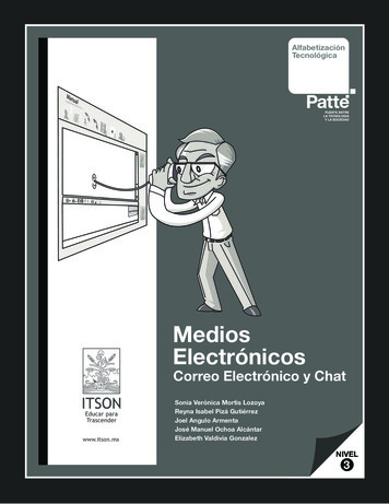
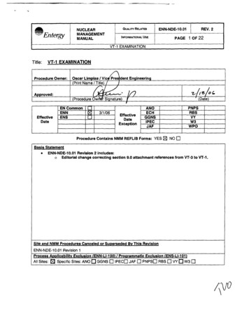
mEntqy- z-NUCLEARMANAGEMENTMANUALATTACHMENT9.1QUALITY RELATEDREV. 2ENN-NDE-10.01PAGE 18OF22lNFORMATlOWL USE(BOLTING)VT-1 EXAMINATIONREPORTWork Document:Component:Report No.:System:Drawing:PageLine #:[7 Direct 0RemoteEquipment:rnLight Meter (aN/A)Acc Rej W Au u uu c l oBolting AttributesICrack-like flawsThread damageCorrosion /WearofCommentsIZJDCIPhysical damage0 0 0Missing / Loose boltingUCICI0 0 c]Fractured bolts, studs or nutsDegraded of protective coatingCoolant leakage near bolting[z10C I U UD C I O0 0 UIOthern o uO D DD U O0 0 0n u uAcceptance Criteria: ASME Section XI 1998 Edition, 2000 minerLevelDateI1 ANI1Date
ITY RELATEDENN-NDE-10.01INFORMATIONAL USEVT-1 EXAMINATIONREPORTPAGEREV. 219OF22(INTEGRALATTACHMENTWELDS)Work Document:Component:Report No.:System:Drawing:Pageofo c l n0 0 00 0 00 0 0n u n000000000000o o n0 0 0IIReviewLevelDateI ANI1Date
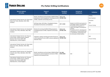
TY RELATEDPAGE 200F22lNFORMATlONAL USEVT-1 EXAMINATIONREPORT(NOZZLEINNERRADIUS)Work Document:Component:Report No.:System:Drawing:PageLine #:0Direct 0Remote0Light Meter (0N/A)Equipment:Nozzle IR AttributesCrack-like surface flawsStructural degradationOtherI AccloI0 OlReiNIAIo 0 n0I OIn 0cllo 0I O clI O 0I OI OI OIOI OInloI OIncl 00cl 0000 00 0REV. 2ENN-NDE-10.01ofComments
a"EntergyNUCLEARMANAGEMENTMANUALlNFORMATlONAL USEREV. 2PAGE 21 OF22IIA A C H M E N9.4TENN-NDE-10.01QUALITY RELATE VT-1 velDateANI1LevelDateDate
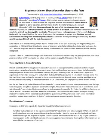
II- - EntersyNUCLEARMANAGEMENTMANUALIQUALITY RELATEDENN-NDE-10.01REV. 2PAGE 2 2 0 F 2 2INFORMATIONAL USEVT-1 EXAMINATIONAITACHMENT9.5L(CONCRETESURFACES)VT-1 EXAMINATIONREPORTWork Document:Component:Report No.:System:Drawing:PageRemarks:1Iof
Reference ASME Boiler and Pressure Vessel Code, Sections V, for the glossary of terms used in Nondestructive Examination (NE). RES PONS1 BI LlTlES SUPERVISOR The Supervisor, charged with the responsibility for NDE at each site, is responsible fo