Transcription
Power SuppliesThe Essential Guide to Power Supplies is designed for power supply users,considering the many aspects of power supplies & DC/DC converters andtheir integration into today’s electronic equipment.The new guide includes details on the latest safety legislation such as thenew IEC standard to replace IEC60950, new requirements for CE markingand the latest energy efficiency levels required by energy star and the EUcode of conduct.Also included are sections on subjects as varied as green mode topologies,power supply de-rating and electrolytic capacitor & power supply lifetime.Whether you’re new to designing-in a power supply or DC-DC converter oran ‘old hand’, this book offers an invaluable resource and all the informationyou’ll need in one easy reference guide.i
ContentsIntroduction to Power Conversion Introduction . . . . . . . . . . . . . . . . . . . . . . . . . . . . . . . . . . . . . . . . . . . . . . . . . . . . . . . . . . . . . . . . . . 1Common Topologies . . . . . . . . . . . . . . . . . . . . . . . . . . . . . . . . . . . . . . . . . . . . . . . . . . . . . . . . . . . 2Linear Power Supplies . . . . . . . . . . . . . . . . . . . . . . . . . . . . . . . . . . . . . . . . . . . . . . . . . . . . . . . . . 11Green Mode Power Supply Topologies . . . . . . . . . . . . . . . . . . . . . . . . . . . . . . . . . . . . . . . . . . . . 12Distributed Power Architectures . . . . . . . . . . . . . . . . . . . . . . . . . . . . . . . . . . . . . . . . . . . . . . . . . 16Input Considerations 18Power Sources . . . . . . . . . . . . . . . . . . . . . . . . . . . . . . . . . . . . . . . . . . . . . . . . . . . . . . . . . . . . . . 18Input Protection . . . . . . . . . . . . . . . . . . . . . . . . . . . . . . . . . . . . . . . . . . . . . . . . . . . . . . . . . . . . . . 27AC Input Current & Harmonics . . . . . . . . . . . . . . . . . . . . . . . . . . . . . . . . . . . . . . . . . . . . . . . . . . 34Real Power, Apparent Power & Efficiency . . . . . . . . . . . . . . . . . . . . . . . . . . . . . . . . . . . . . . . . . . 37Earthing/Grounding . . . . . . . . . . . . . . . . . . . . . . . . . . . . . . . . . . . . . . . . . . . . . . . . . . . . . . . . . . . 42DC Output Considerations 145Output Regulation . . . . . . . . . . . . . . . . . . . . . . . . . . . . . . . . . . . . . . . . . . . . . . . . . . . . . . . . . . . . 45High Peak Loads . . . . . . . . . . . . . . . . . . . . . . . . . . . . . . . . . . . . . . . . . . . . . . . . . . . . . . . . . . . . . 47Powering Light Emitting Diodes (LED’s). . . . . . . . . . . . . . . . . . . . . . . . . . . . . . . . . . . . . . . . . . . . 49Ripple & Noise . . . . . . . . . . . . . . . . . . . . . . . . . . . . . . . . . . . . . . . . . . . . . . . . . . . . . . . . . . . . . . . 54Output Protection . . . . . . . . . . . . . . . . . . . . . . . . . . . . . . . . . . . . . . . . . . . . . . . . . . . . . . . . . . . . 56Series & Parallel Operation. . . . . . . . . . . . . . . . . . . . . . . . . . . . . . . . . . . . . . . . . . . . . . . . . . . . . . 60Redundant Operation . . . . . . . . . . . . . . . . . . . . . . . . . . . . . . . . . . . . . . . . . . . . . . . . . . . . . . . . . 62Power Supply De-rating. . . . . . . . . . . . . . . . . . . . . . . . . . . . . . . . . . . . . . . . . . . . . . . . . . . . . . . . 63Status Signals & Controls . . . . . . . . . . . . . . . . . . . . . . . . . . . . . . . . . . . . . . . . . . . . . . . . . . . . . . 66Thermal Management75 System Cooling Fan Selection . . . . . . . . . . . . . . . . . . . . . . . . . . . . . . . . . . . . . . . . . . . . . . . . . . . 75 Cooling Power Supplies. . . . . . . . . . . . . . . . . . . . . . . . . . . . . . . . . . . . . . . . . . . . . . . . . . . . . . . . 78 Cooling Power Modules. . . . . . . . . . . . . . . . . . . . . . . . . . . . . . . . . . . . . . . . . . . . . . . . . . . . . . . . 81 Baseplate Cooling . . . . . . . . . . . . . . . . . . . . . . . . . . . . . . . . . . . . . . . . . . . . . . . . . . . . . . . . . . . . 82 Electrolytic Capacitor Lifetime . . . . . . . . . . . . . . . . . . . . . . . . . . . . . . . . . . . . . . . . . . . . . . . . . . . 85ii
Reliability88 Terminology. . . . . . . . . . . . . . . . . . . . . . . . . . . . . . . . . . . . . . . . . . . . . . . . . . . . . . . . . . . . . . . . . 88 Factors Affecting Reliability . . . . . . . . . . . . . . . . . . . . . . . . . . . . . . . . . . . . . . . . . . . . . . . . . . . . . 90 System Reliability. . . . . . . . . . . . . . . . . . . . . . . . . . . . . . . . . . . . . . . . . . . . . . . . . . . . . . . . . . . . . 93Legislation 94Power Supply Safety . . . . . . . . . . . . . . . . . . . . . . . . . . . . . . . . . . . . . . . . . . . . . . . . . . . . . . . . . . 94Medical Safety . . . . . . . . . . . . . . . . . . . . . . . . . . . . . . . . . . . . . . . . . . . . . . . . . . . . . . . . . . . . . . . 98High Voltage Safety Testing. . . . . . . . . . . . . . . . . . . . . . . . . . . . . . . . . . . . . . . . . . . . . . . . . . . . 103Electromagnetic Compatibility (EMC) . . . . . . . . . . . . . . . . . . . . . . . . . . . . . . . . . . . . . . . . . . . . . 105CE Marking . . . . . . . . . . . . . . . . . . . . . . . . . . . . . . . . . . . . . . . . . . . . . . . . . . . . . . . . . . . . . . . . 112Defense and Avionics EMC Standards . . . . . . . . . . . . . . . . . . . . . . . . . . . . . . . . . . . . . . . . . . . 114Power Systems for Railway Applications . . . . . . . . . . . . . . . . . . . . . . . . . . . . . . . . . . . . . . . . . . 119No Load Power Consumption & Efficiency Legislation for External Power Supplies. . . . . . . . . . 122Energy Efficiency of Component Power Supplies . . . . . . . . . . . . . . . . . . . . . . . . . . . . . . . . . . . 126Technology Editorials ditorialEditorialEditorial1.2.3.4.128Understanding Efficiency. . . . . . . . . . . . . . . . . . . . . . . . . . . . . . . . . . . . 128Cooling without a Fan . . . . . . . . . . . . . . . . . . . . . . . . . . . . . . . . . . . . . . 131Removing Heat from Sealed Enclosures . . . . . . . . . . . . . . . . . . . . . . . . 134Selecting Power Supplies for LED Lighting Applications . . . . . . . . . . . . 137Further technical articles are available online at: www.xppower.comGlossary141 Glossary . . . . . . . . . . . . . . . . . . . . . . . . . . . . . . . . . . . . . . . . . . . . . . . . . . . . . . . . . . . . . . . . . . 141 Prefix Codes . . . . . . . . . . . . . . . . . . . . . . . . . . . . . . . . . . . . . . . . . . . . . . . . . . . . . . . . . . . . . . . 153 SI Unit Codes . . . . . . . . . . . . . . . . . . . . . . . . . . . . . . . . . . . . . . . . . . . . . . . . . . . . . . . . . . . . . . 154Index155iii
Edited by Gary BocockIssue 1iv
Introduction to Power Conversion IntroductionElectronic equipment requires low voltage DC power supplies. These DC supplies must be accuratelyregulated with low noise and present a low output impedance to support load changes. They mustalso provide protection for both the power supply itself and the end equipment.AC power supplies and DC/DC converters are designed to provide these desirable characteristics andalso provide isolation from input to output for safety, noise reduction and transient protection whererequired.End applications may require a combination of AC/DC and DC/DC or Non Isolated Point Of Load(NIPOL or POL) converters to support the various power supply, power system and isolation needs ofsub systems such as control electronics, battery charging, communications ports andelectromechanical or applied parts.Standard AC power supplies are typically designed to support global markets offering wide inputrange capability and standard DC/DC converters commonly offer 2:1 or 4:1 input ranges to cater formultiple nominal battery voltages. These wide or universal input ranges broaden potential markets forindividual standard products increasing volumes and reducing cost. Standard product designs alsoincorporate features to cover multiple applications and carry multiple agency approvals to supportworld-wide requirements.For high volume equipment it may be advantageous to consider an application specific or custompower solution where the initial design & approval costs and risks may be outweighed by reduced unitcost by ensuring that the power supply has only the exact electrical and mechanical propertiesrequired for the end application. However, the ever growing and extensive range of standard formatpower supply products available often negates this approach.AC power supplies and DC/DC converters come in many different mechanical formats or packages tosuit a wide variety of end applications and power ranges. They may be integrated into the endequipment in open frame, PCB mount, chassis mount, base plate cooled or enclosed formats, bekept external to the equipment in plug top, desk top or rack mounted formats or may be designed tosuit specific applications such as DIN Rail equipment.Switching power supply and DC/DC converter performance continues to advance. Developments inareas such as ZVS (Zero Voltage Switching) & ZCS (Zero Current Switching) resonant topologies &synchronous rectification techniques provide higher conversion efficiency and reduced heatdissipation. These advances allow higher switching frequencies and along with advanced packagingtechniques mean continued improvement in power density reducing overall volume and waste heat.Efficiencies above 90% are commonplace in AC power supplies with products peaking as high as95%.The Essential Guide to Power Supplies addresses input & output specifications, EMC considerations,safety legislation, cooling & thermal management, reliability, lifetime and much more.1
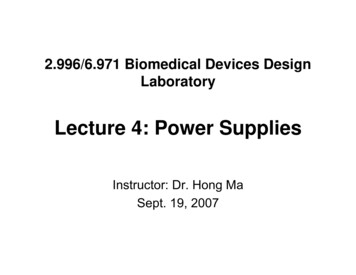
Introduction to Power Conversion Common TopologiesIsolated Fly-back ConverterIsolated fly-back converters are typically used in power converters up to 150 W. The topology usesonly one major magnetic component, which is a coupled inductor providing both energy storage andisolation. Energy transfer to the secondary and the load occurs during the switching element off-time.DVcNsNpLOADS1FEEDBACK& DRIVEIsolated Fly-back ConverterPWMVDS(S1)VcIDS(S1)VNSIDt onTt offThis topology provides a low cost means of converting AC to DC power due to its simplicity andlow component count. The power level is restricted by the high levels of ripple current in the outputcapacitor and the need to store high levels of energy in the coupled inductor in a restricted volume.Flyback converters commonly utilize valley or transition mode controllers to reduce switching lossesand green mode controllers to minimize no load power consumption.The fly-back converter is used in DC/DC converters but only at low power ( 50 W) due to the lowinput voltage and high ripple currents. Waveforms above are for discontinuous mode.2
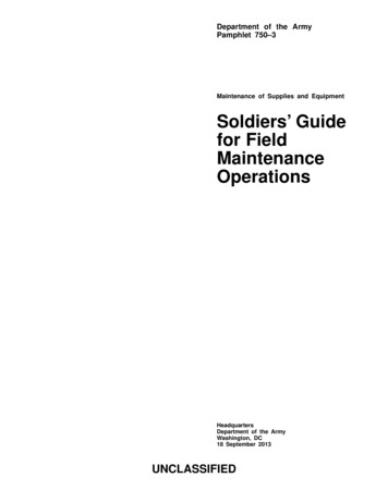
Introduction to Power ConversionForward ConverterForward converters are typically used in power supplies which operate in the range 100-300 W. Thistopology uses two major magnetic components; a transformer and an output inductor. Energytransfer to the secondary and the load occurs during the switching element on-time. Forwardconverters are used in both AC power supplies and DC/DC converters.LD1VcNsNpD2LOADS1FEEDBACK& DRIVEForward ConverterPWMVDS(SI)VcIDS(SI)VNSID1ID2ILt ont offTThere is no energy stored in the transformer; energy is stored in the output stage of the converter inthe inductor and capacitor. The output inductor reduces the ripple currents in the output capacitorand the volume of the transformer is dependent on switching frequency and power dissipation.3
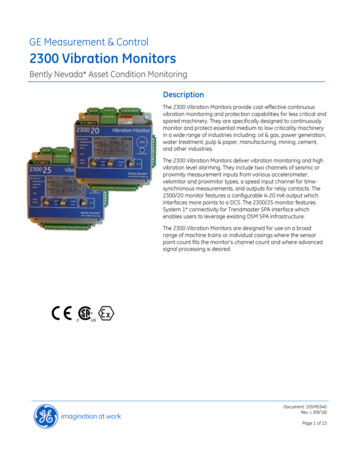
Introduction to Power ConversionTwo Transistor Forward ConverterAt the higher end of the power spectrum, two transistor forward converters can be employed (seebelow). The two switching elements operate simultaneously, halving the voltage on each switchingelement and allowing the use of a device with a higher current rating.VcS2NpLD1NsD2LOADS1FEEDBACK& DRIVETwo Transistor Forward ConverterPWMVcVDS(S1)VDS(S2)VcIDS(S1 & S2)VNSID1ID2ILt ont offTAs the power rating increases, it is desirable to utilize the transformer core more efficiently by drivingit through two quadrants of its available area of operation, rather than the one utilized in forwardconverters. This is achieved in half bridge or full bridge converters.4
Introduction to Power ConversionHalf Bridge & Full Bridge ConvertersHalf bridge converters are utilized in power supplies in the power range of 150-1000 W. Thistopology also uses two major magnetic components, a transformer and an output inductor, but inthis case the transformer core is better utilized than in a forward converter. The switching elementsoperate independently, with a dead time in between, switching the transformer primary both positiveand negative with respect to the center point.VcD1S2NpS1LLOADNs1Ns2D2FEEDBACK& DRIVEHalf Bridge ConverterPWMVc1/2 VcVDS(S1)Vc1/2 VcVDS(S2)IDS(S1)IDS(S2)VNS1VNS2ID1ID2ILt ont offT5
Introduction to Power ConversionEnergy is transferred to the secondary and the load during each switching element on-time byutilizing a split secondary winding. This has the added benefit of doubling the switching frequencyseen by the secondary, helping to reduce the volume of the output inductor and capacitor requiredand halving the voltage seen by each switching element. In higher power solutions a full bridgeconverter can be employed (see below).VcD1S4S2NpS3S1LNS1LOADNS2D2FEEDBACK& DRIVEFull Bridge ConverterPWMVc1/2 VcVDS(S1)Vc1/2 VcVDS(S2)IDS(S1 & S4)IDS(S2 & S3)VNS1VNS2ID1ID2ILt ont offTThis topology will provide double the output power for the same primary switching current, butincreases the complexity of switching element drive circuits, compared to the half bridge. Half bridgeand full bridge converters are used in AC input power supplies. There is also a trend to util
power solution where the initial design & approval costs and risks may be outweighed by reduced unit cost by ensuring that the power supply has only the exact electrical and mechanical properties required for the end application. However, the ever growing and extensive range of standard format power supply products available often negates this approach. AC power supplies and DC/DC converters .