Transcription
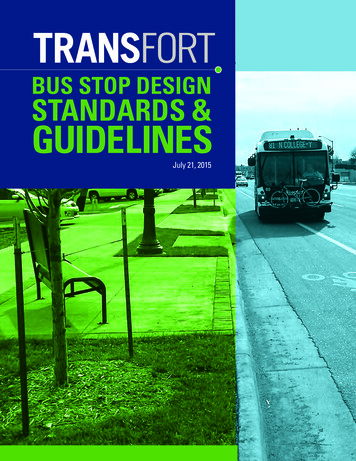
BUS STOP DESIGNSTANDARDS &GUIDELINESJuly 21, 2015
ACKNOWLEDGEMENTS:Technical Advisory CommitteeNoah Al Hadidi, CSU StudentSarah Allmon, Barrier Busters Public Transportation Advisory Group (PTAG)Vivian Armendariz, CitizenMichael Devereaux, PTAG, Commission on DisabilityKathryn Grimes, Bike Advisory CommissionJamie Rideoutt, Lamar Advertising CompanyEd Roberts, Transportation Board (past member)Carol Thomas, Transfort Safety, Security and Training ManagerProject Management TeamEmma Belmont, Transfort — Transit PlannerSteve Gilchrist, Traffic — Traffic EngineerAaron Iverson, FC Moves — Senior Transportation PlannerTim Kemp, Engineering — Civil Engineer IIITom Knostman, Streets — Pavement EngineerKathleen Walker, Transfort — Operations ManagerGraphics and FormattingSlate CommunicationsBHA Design IncorporatedTRANSFORT BUS STOP DESIGN STANDARDS AND GUIDELINES
CONTENTS1. OVERVIEW1.1 PURPOSE1.2 T HE DEVELOPMENT OF THESESTANDARDS AND GUIDANCE1.3 I NTEGRATION WITH OTHERSTANDARDS GUIDANCE2. THE BIG PICTURE4. CURB-SIDECHARACTERISTICS4.1 INTRODUCTION4.2 U NIVERSAL DESIGN ANDADA ACCESSIBILITY4.3 BUS STOP TYPES4.4 AMENITIES4.5 BUS STOP TYPE DETERMINATION2.1 INTRODUCTION2.2 TRANSIT SYSTEM OVERVIEW2.3 B US STOP INSTALLATION ANDUPGRADE — HOW DOES IT HAPPEN?2.4 O BSTACLES TO IMPROVINGTRANSIT INFRASTRUCTURE2.5 B US STOP MAINTENANCEAND ADVERTISING3. STREET-SIDECHARACTERISTICS3.1 INTRODUCTION3.2 STOP SPACING3.3 STOP LOCATING3.4 IN-STREET DESIGN3.5 TECHNICAL DETAILSTRANSFORT BUS STOP DESIGN STANDARDS AND GUIDELINES5. NEXT STEPS5.1 INTRODUCTION5.2 T RANSFORT BUS STOPIMPROVEMENT PLAN5.3 RECOMMENDED FUTURE ACTIONS6. APPENDIX6.1 BUS STOP DEVELOPMENT FORM6.2 LAND USE CODE SECTION 3.6.56.3 T ECHNICAL DESIGNS (As Incorporated intoLarimer County Urban Area Street Standards)6.4 C ITIZEN ADVISORY COMMITTEELETTER OF SUPPORT
1. OVERVIEW1.1 PURPOSEThe purpose of the Bus Stop Design Standards and Guidelines document is to assist City staff,developers, local partners and private property owners in locating and designing bus stops andtheir associated passenger amenities within the City of Fort Collins as well as the greater Transfortservice area. The document consists of five chapters: O verview — discusses how to use the standards and guidance The Big Picture — discusses the transit network as it currently exists and the envisionedfuture of transit service in Fort Collins S treet-side Characteristics — discusses the factors associated with the roadway thatinfluence bus operations C urb-side Characteristics — discusses the factors associated with the comfort, safety andconvenience of patrons at bus stops N ext Steps — discusses Transfort’s approach to pursue capital improvements and outlinesrelated action items related to bus stop accessibilityTRANSFORT BUS STOP DESIGN STANDARDS AND GUIDELINES1
1.2 THE DEVELOPMENT OF THESESTANDARDS AND GUIDANCEThis guidance document was created with the assistance of a Citizen Advisory Committee (CAC),created by Transfort, comprised of local transit riders, cycling advocates, safety specialists, urbandesigners, students, media professionals, Transfort staff and other interested parties. The CACmembers included individuals with a wide range of abilities and experiences with the transit network.A project management team (PMT) of City staff also assisted in the development of this document.This group focused on the technical components and safety considerations as they relate to busstops. The following City departments were represented in the PMT: Engineering, FC Moves,Planning, Streets, Traffic, and Transfort.In addition, Transit Cooperative Research Program (TCRP) Report 19 – Guidelines for the Locationand Design of Bus Stops, as well as various other transit agency bus stop design documents,provided best practices and general guidance in the development of the standards and guidanceoutlined in this document.1.3 INTEGRATION WITH OTHERSTANDARDS AND GUIDANCEThere are various tools that work in tandem with this standards and guidance document. Within theTransfort department, other important guidance tools that may provide guidance on facilities andservices include: Transfort Strategic Operating Plan (TSOP), Transfort Operating Manual (TOM),and Transfort Service Standards. Additional documents that govern site development include:Fort Collins Land Use Code (LUC) and Larimer County Urban Area Street Standards (LCUASS). Ifconflicts arise between these documents, the more specific and/or stringent standard will apply.TRANSFORT BUS STOP DESIGN STANDARDS AND GUIDELINES2
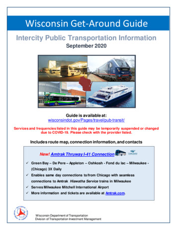
2. THE BIG PICTURE2.1 INTRODUCTIONBus stops are a critical part of the transit system as they serve as the first point of contact betweenthe customer and the service. In addition, bus stop placement throughout the community actsto promote alternative modes of transportation to the traveling public. The spacing, location anddesign all affect the operation of the transit system and, in turn, the transit patron’s satisfaction.The standards and guidance in this document are intended to guide the design of transit stops thatcomplement their immediate surroundings, meet the transit patron’s comfort and safety needs,and support an efficient transit network.The placement of transit stops is guided by safety considerations, community context, patron’sorigins and destinations, opportunity, and Transfort’s strategic planning efforts. The TSOP isTransfort’s long range planning tool; however, it is possible that community growth and change willoccur in ways not anticipated by the TSOP, and therefore routes and bus stops may be different fromthose envisioned in the TSOP. The TSOP proposed long range routes are depicted in Figure 2 below.2.2 TRANSIT SYSTEM OVERVIEWThe City of Fort Collins operates its own transit system, which is branded as Transfort. Transfortoperates fixed route transportation within the City of Fort Collins and in parts of unincorporatedLarimer County. Complementary paratransit service is contracted to and operated by VeoliaTransportation. A regional express route, known as FLEX, is provided through a partnershipbetween Fort Collins, Loveland, Berthoud, Longmont and Boulder County. Transfort bus stopsare located within Fort Collins city limits as well as in unincorporated Larimer County, the City ofLoveland, the Town of Berthoud, Boulder County and the City of Longmont.Transfort’s route map (August 2015) is provided below in Figure 1. Following Figure 1 is a mapof the long range vision for transit service in and surrounding Fort Collins, Figure 2. This mapillustrates the TSOP vision for a full transition into a productivity-based grid system. It incorporatesthe Phase 3 planned routes, along with additional recommendations from other adopted plansTRANSFORT BUS STOP DESIGN STANDARDS AND GUIDELINES3
and new routes that have been added since the TSOP’s adoption. The purpose of this map is toindicate where new bus stops will be located as development occurs throughout the city.Figure 1 — Transfort All Routes Map (Effective August 2015)I-25TIMBERLINE RD.LEMAY AVE.COLLEGE AVE.LAPORTE AVE.SHIELDS ST.TAFT HILL RD.OVERLAND TRAIL9818VINE DR.91DTC9210335ELIZABETH ST.3114MULBERRY ST.CTC3226PROSPECT RD.18197DRAKE RD.HORSETOOTH RD.12HARMONY RD.16STCTRANSFORT BUS STOP DESIGN STANDARDS AND GUIDELINES4
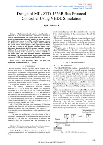
Figure 2 — Transfort Strategic Operating Plan Phase 3 Routes and Proposed ChangesTRANSFORT BUS STOP DESIGN STANDARDS AND GUIDELINES5
2.3 BUS STOP INSTALLATION ANDUPGRADE — HOW DOES IT HAPPEN?There are just over 500 existing bus stops in the Transfort system; of these, some meet thestandards outlined in this document and some do not. In addition to existing bus stops thatTransfort currently serves, the TSOP sets forth a plan for expanded service which will require newtransit facilities throughout Transfort’s service area.There are a variety of ways transit facilities are installed and upgraded throughout the Transfortsystem, and they are described below: Transfort’s Capital Improvement Plan — The Improvement Plan, which is based onlocation specific criteria, identified in the Bus Stop Development Form (Appendix 1) andSection 4.5, prioritizes bus stop improvements in the Transfort Service Area. Transfortanticipates an annual budget of 100,000, based on dedicated tax revenue (Building onBasics), for bus stop improvements. It is estimated that this amount will fund approximately7–10 bus stops annually. Transfort also pursues grants to fund additional improvements.Improvements are generally implemented according to the Improvement Plan, but obstaclesdo arise as described in Section 2.4. Transfort’s Service Agreement for Bus Stops — Transfort contracts with an advertisingcompany for the installation, provision of passenger amenities and maintenance of Transfort’sbus stops. This agreement permits Transfort to request solid surface upgrades to bus stopsthat are located within public right-of-way (ROW) and installation of passenger amenitiesat bus stops in Transfort’s service area. In a typical year, this agreement provides for theupgrade of approximately 10 bus stops. D evelopment and/or Redevelopment — As properties develop and redevelop within citylimits the City’s Land Use Code (LUC) requires that the development accommodate boththe existing and planned transit network (LUC Section 3.6.5 text included in Appendix 2).This requires developers to provide the necessary transit infrastructure and passengeramenities, if applicable, on or adjacent to their property. Developer responsibilities mayinclude: dedicating additional public ROW; dedicating a Transit Easement; installation of abus stop solid surface; installation of a bus pullout; and installation of or payment in lieu forTRANSFORT BUS STOP DESIGN STANDARDS AND GUIDELINES6
the applicable bus stop passenger amenities, all in accordance with the standards set forthin this document. Transfort does not have control over which stops are improved via this method. Bus stopimprovements may not be in accordance with the Improvement Plan Priorities set forthin this document. C ity Capital Improvement and Street Maintenance Projects — Every year theCity’s Engineering and Streets Departments implement capital improvements and streetmaintenance. These departments manage infrastructure improvements and work withTransfort to help upgrade bus stops, as needed in the area of the project’s impact. Sincestops improved through this method are opportunistic, improvements may not reflect thesame priorities as listed in the Improvement Plan.TRANSFORT BUS STOP DESIGN STANDARDS AND GUIDELINES7
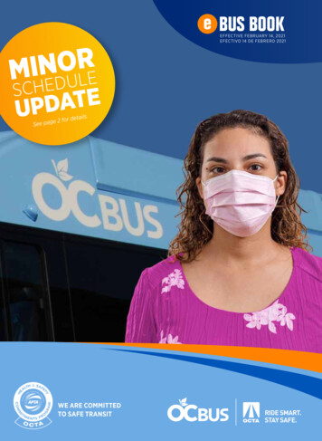
2.4 OBSTACLES TO IMPROVINGTRANSIT INFRASTRUCTUREMany obstacles exist outside of Transfort’s control, which makes providing quality transit facilitieschallenging at times. Obstacles to improving bus stops include: available space (including publicROW) for stop infrastructure (solid surface and passenger amenities); accessible neighborhoodsidewalks connecting to stops; accessible street crossings; and temporary obstacles such as thosedue to weather events like snow, rain or hail. Transfort actively works with other City departmentsto make improvements to the sidewalk network and to add accessible bus stops in conjunctionwith City construction activities. However, it will take many years for all stops to be improvedbecause infrastructure deficiencies are widespread. Images 1, 2 and 3 below demonstrate someof the obstacles that limit transit facility improvements.Image 1Image 2Laporte and Overland Eastbound (EB)Obstacles: Limited public ROW No sidewalksImage 3Shields and Swallow Northbound (NB)Obstacles: Limited public ROWHarmony and Corbett (EB)Obstacles: Covered section of ditch runs between sidewalk and edge of streetTRANSFORT BUS STOP DESIGN STANDARDS AND GUIDELINES8
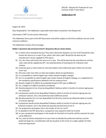
2.5 BUS STOP MAINTENANCEAND ADVERTISINGTransfort, like many transit agencies across the nation, utilizes advertising revenue to provideboth maintenance of and passenger amenities at bus stops. Transfort contracts this service withan advertising contractor, allowing them to advertise at Transfort bus stops. In return, Transfortbenefits from a portion of the advertising revenue, as well as the contractor’s maintenance of busstops (including snow removal) and the contractor’s provision of passenger amenities and solidsurface installation at locations within public ROW. However, advertising is not permitted at allbus stops within Transfort’s network. In single family residential areas, for example, advertisingis limited to side-yards. In addition, certain areas may not be appropriate for advertising, such ashistorically significant sites. In such cases, Transfort has a limited number of non-advertising busstop benches and shelters that can be used if advertising is deemed to be incompatible with thecharacter of the area.Images 4–7 below are examples of advertising at Transfort bus stops.Image 4Image 5Harmony and Timberline (EB)Harmony and Larkbunting (WB)Image 6Image 7Rock Creek at Fossil Ridge High School (EB)Taft Hill and Drake (NB)TRANSFORT BUS STOP DESIGN STANDARDS AND GUIDELINES9
3. STREET-SIDE CHARACTERISTICS3.1 INTRODUCTIONThis section discusses preferred and alternative street-side or in-street stop designs. Street-sidecharacteristics refer to features associated with the roadway that influence transit operations.These features include elements such as: traffic speeds, street design, intersection design andthe location of acceleration/deceleration lanes. Street-side features influence the location of andin-street design of bus stops. It is important to note that since stop designs were developedbased on standard roadway characteristics, the on-site context may call for locations or designsthat are tailored to that context. Ultimately, Transfort staff, with the input from the City’s Traffic,Engineering and FC Moves Departments, will make the final decision on the location and designthat is appropriate for a given situation.Image 8Street-sideCharacteristicsTRANSFORT BUS STOP DESIGN STANDARDS AND GUIDELINES10
3.2 STOP SPACINGStop spacing refers to the distance between stops along a bus route. Stop spacing takes intoconsideration the trade-offs between vehicle travel times and walking distances to bus stops.While more frequently placed bus stops reduce walking distances, it also slows down bus service.In contrast, longer distances between stops increases vehicle speed but may result in customershaving to walk longer distances to get to bus stops. This is described in TCRP’s Report 19 as tradeoffs between operating efficiencies and customer accessibility, as follows:Table 1 — Trade-offs of Stop SpacingClose stops(every block or⅛ mile – ¼ mile spacing) Short walking distances More frequent stops, creating longer travel timeFurther distance between stops(Beyond ¼ mile spacing) Longer walking distances Less frequent stops, creating shorter travel timeTCRP Report 19 also describes the industry standards for bus stop spacing typically beingsubdivided by land use types/densities or locating stops near major trip generators. This suggestsusing closer spaced stops in more densely populated areas, such as the central business core,and increasing space between stops when approaching more suburban and rural areas of thecommunity. In addition Bus Rapid Transit (BRT) type routes generally suggest an increaseddistance between stops to decrease travel times. Table 2 below describes typical ranges for thedifferent land use environments.Transfort uses these ranges as references, but in general the main considerations for bus stoplocating and spacing are safety, such as reducing bus and vehicle conflicts, and major tripgenerators, such as, community activity centers and concentrations of residences and businesses.Where feasible, stops shall be located approximately ¼ mile apart. In locations where stop spacingis more then ⅓ mile apart, a midpoint stop may be considered if adjacent land uses warrant suchadditional stop placement.TRANSFORT BUS STOP DESIGN STANDARDS AND GUIDELINES11
Table 2 — Recommended Bus Stop SpacingEnvironmentRoute TypeSpacing RangeUrban Area (within a CityPlan Activity Center, seeFigure 20 in Section 4.5)Local Route⅛ – ¼ MileExpress or Bus Rapid Transit Route½ – 1 Mile or As NeededSuburban AreaLocal Route¼ – ½ MileExpress or Bus Rapid Transit Route1 Mile or As NeededLocal RouteAs NeededExpress or Bus Rapid Transit RouteAs NeededRural Area3.3 STOP LOCATINGThere are three location options for bus stops: near-side, far-side and mid-block, as shown inFigure 3 below. Far-side stops are, in general, Transfort’s preferred stop location because theyare shown to be the safest for passengers exiting the bus and minimize conflicts with othervehicles. However, a mid-block or near-side stop may be more appropriate in some situations.Many factors influence the location of stops, such as site specific safety considerations, trafficpatterns, intersection geometry, passenger origins and destinations, pedestrian accessibility, routedesign and available space. Transfort staff determine which stop location is most appropriate foreach individual situation, and Table 3 may be used to help make a decision based on the tradeoffs of each possible location.TRANSFORT BUS STOP DESIGN STANDARDS AND GUIDELINES12
Figure 3 — Near-Side, Far-Side and Mid-Block Stops LocationsTRANSFORT BUS STOP DESIGN STANDARDS AND GUIDELINES13
Table 3 — Recommended Bus Stop LocationSTOP LOCATIONADVANTAGESDISADVANTAGESNEAR-SIDE STOPUse if: Destinations arefocused at thenear-side corner Allows passengers to access busesclose to the crosswalk Increases conflict withright-turning vehicles Eliminates the potential for doublestopping — passenger loading canoccur when bus is stopped atthe signal May result in stopping busesobscuring curbside traffic controldevices and crossing pedestrians Route pattern calls fornear-side location Available space islimited on far-side May block the through traffic lanesduring peak hours May cause sight distanceproblems for pedestriansand motorists May increase rear-end accidents ifdrivers aren’t anticipating the busstopping before the intersection Vehicles may attempt to turn infront of a stopped bus that isbeginning to pull awayFAR-SIDE STOPUse if: Destinations are onboth sides of streetor on the far side ofthe intersection Minimizes conflicts between rightturning vehicles and buses Allows for additional right-turncapacity (because bus is notstopping in the right turn lane) Minimizes sight distancedifficulties on approachto intersections Encourages pedestrians to crossbehind the bus Stopped buses may blockintersections duringcongested periods May cause a bus to stop twice inshort order: once at a red lightand once at the bus stop May increase rear-end accidents ifdrivers do not anticipate the busstopping after the intersection Bus can merge into traffic moreeasily, taking advantage of gapsMID-BLOCK STOPUse if: Block size is largeand/or destinationsare focusedmid-block Minimizes sight distancedifficulties at intersections Encourages passengers to crossmid-block (jaywalk) Removes the influence oftraffic congestion occurring atintersections Increases walking distance forpatrons to cross at intersections Route pattern callsfor mid-block stopTRANSFORT BUS STOP DESIGN STANDARDS AND GUIDELINES14
3.4 IN-STREET DESIGNThe In-Street Design refers to the location that the bus stops in the street to approach the busstop, such as in a bus pullout, travel lane, bike lane or on a road shoulder. Determining whatdesign is appropriate depends on safety considerations, street design, available space, ridershipand other factors. Most of Transfort’s buses stop in bike or travel lanes, but bus pullouts may beused in areas where there is high ridership, a large number of route transfers or where traffic isconsidered to be high volume. Queue jumps refer to an intersection design that allows the busto move ahead of queueing traffic to progress through high congestion intersections quicker.Queue jumps and bus pullouts typically originate from recommendations of a corridor, sub-area orservice-related planning effort (e.g. Harmony Road Enhanced Travel Corridor Alternatives Analysis,Lincoln Corridor Plan, or West Central Area Plan). In addition, a bus pullout may be required whenmultiple routes transfer at the location. Foothills Mall provides an example of such a situation.In-Street Design alternatives are illustrated below in Figures 4 and 5. Bus pullouts, shall be designedto the detail shown in LCUASS drawing 711. The flow chart in Figure 6 helps to determine whatIn-Street Design is appropriate, and the trade-off of each design is described in Table 4.TRANSFORT BUS STOP DESIGN STANDARDS AND GUIDELINES15
Figure 4 — In-Street Bus Stop Design AlternativesTRANSFORT BUS STOP DESIGN STANDARDS AND GUIDELINES16
Figure 5 — Bus Stop Zone Dimensions (where on-street parking is present)TRANSFORT BUS STOP DESIGN STANDARDS AND GUIDELINES17
Figure 6 — In-Street Design RecommendationsIs a designrecommended as partof an adopted plan?YESUse designidentifiedin the PlanNOIs the stop atransfer location?YESWhat volumeof transfers areanticipated?HIGH VOLUME(BRT connections ormore than 3 routesserve the stop)A Bus Pullout orOpen Bus Bay isappropriateNOIs there on-streetparking?LOW VOLUME(2-3 low frequency routes)How many travel lanes areon the adjacent road?1 in eachdirection2 or more ineach directionYESNOA Bulbout stopis most likelyappropriateA Curbside stopis appropriateA Bus Pullout orOpen Bus Bay isappropriateTRANSFORT BUS STOP DESIGN STANDARDS AND GUIDELINES18
Table 4 — Recommended Bus Stop In-Street DesignSTOP LOCATIONADVANTAGESDISADVANTAGESCURBSIDE STOP(Typical) Provides easy approach for busdrivers and results in minimaldelay to the bus Can cause traffic delays since busstops in the travel lane Simple design and inexpensiveto install May cause drivers to make unsafepassing maneuvers Easy to relocateBUS PULLOUT(Route transfer stopand/or on roads withtwo travel lanes) Bus is out of travel lane,minimizing delay to traffic Re-entry into congested traffic canbe difficult and cause delays Passengers board/alight outof traffic Expensive to install, makingrelocation difficult/expensiveOPEN BUS BAY Allows the bus to deceleratein the intersection See Bus Pullout disadvantages See Bus Pullout advantagesQUEUE JUMP Allows bus to bypassqueued traffic May delay right turning vehicles See Bus Pullout disadvantages See Bus Pullout advantagesBULBOUT/NUB(For locations withon-street parking) Removes fewer parking spacesthan others Costs more to install compared tocurbside stops Decreases walking distances tobus stops for pedestrians See Curbside Stop disadvantages Provides additional sidewalk areafor passengers Results in minimal delay for busesTRANSFORT BUS STOP DESIGN STANDARDS AND GUIDELINES19
4. CURB-SIDE CHARACTERISTICS4.1 INTRODUCTIONThis section describes criteria that all bus stops shall meet, provides preferred layout of passengeramenities at stops and recommends how amenities should be distributed throughout the Transfortservice area. Curbside characteristics refer to features associated with the comfort, safety andconvenience of customers at bus stops outside of the roadway. These features include factors likesidewalk width, connections to adjacent land uses, and bus stop passenger amenities such asshelters, benches, bike racks, trash and recycling receptacles and lighting. Newly constructed oraltered bus stops shall meet the standards in this section to the maximum extent feasible.Image 9Curb-sideCharacteristicsTRANSFORT BUS STOP DESIGN STANDARDS AND GUIDELINES20
4.2 UNIVERSAL DESIGN ANDADA ACCESSIBILITYThe Americans with Disabilities Act of 1990 regulated enforceable accessibility standards fornew construction and alterations to places of public accommodation, which include bus stops.The 2010 ADA Standards for Accessible Design, the most recent guidance, outlines the followingfour basic principles to accomplishing ADA accessibility at bus stops, as it applies to all newlyconstructed or altered Transfort bus stops.1) Surface — the bus stop boarding and alighting area shall have a firm, stable surface;2) Dimensions — the bus stop boarding and alighting area shall provide a clear length of 8'minimum, measured from the curb, and a clear width of 5' minimum, measured parallel tothe roadway.Figure 6 — ADA Dimensions of Bus Boarding and Alighting Area3) Connection — the bus stop boarding and alighting area shall be connected to streets, sidewalks,or pedestrian paths by an accessible route, of at least 4' wide.4) Slope — the slope of the bus stop boarding and alighting area shall be the same as the roadwayto the maximum extent practical, and not steeper than 1:48, a 2% grade.TRANSFORT BUS STOP DESIGN STANDARDS AND GUIDELINES21
If a bus stop has a shelter, there shall be a minimum clear floor space of 30" wide by 48" deep insidethe shelter and an accessible path leading from the shelter to the boarding and alighting area.Figure 7 — ADA Interior Bus Shelter Space4.3 BUS STOP TYPESTransfort has four typical stop types tailored to the context of each stop area. Higher ridershipareas or areas with high concentrations of youth, senior, disabled or low-income populations arerecommended to have a higher level of patron amenities such as a shelter, bench, bike rack,trash receptacle and lighting. Lower ridership areas may have fewer amenities. The Bus StopDevelopment Form (Appendix 1) will assist in determining what stop type is appropriate. The stoptypes are described below:TRANSFORT BUS STOP DESIGN STANDARDS AND GUIDELINES22
T ype I – Sign Stop — A bus stop with a bus stop sign and basic ADA accessible landingsurface are the primary features of this stop type, meaning there is no bench or shelter. Thisis the most basic stop type and is appropriate for low land-use density and low ridership areas.Figures 8 and 9 and images 10 and 11 show standard and constrained options for this type ofstop, depending on the available right-of-way and sidewalk design.Figure 8Type I Standard (Detached sidewalk)Figure 9Type I Constrained (Attached sidewalk)Images 10 and 11 — Existing Type I Standard Stop Examples:Shields and Rolland Moore Park SB Bus StopTRANSFORT BUS STOP DESIGN STANDARDS AND GUIDELINESHarmony and Taft Hill EB Bus Stop23
Type II – Bench Stop — This describes a bus stop with a stand-alone bench as the primaryfeature, and which does not include a shelter. The stop should also have a bus stop sign, bikerack and trash receptacle. The most appropriate use of Bench Stops is areas with low to midridership potential. Figures 10 and 11 and images 12 and 13 show standard and constrainedoptions for Type II – Bench Stops.Figure 10Type II Standard (Detached sidewalk)Figure 11Type II Constrained (Attached sidewalk)Images 12 and 13 — Existing Type II Standard and Constrained Examples(to comply with above design, these stops need the addition of a bike rack and trash receptacle)Shields and Centre Avenue NB Bus StopTRANSFORT BUS STOP DESIGN STANDARDS AND GUIDELINESLincoln Avenue and Buckingham Park WBBus Stop24
Type III – Shelter Stop — This describes a bus stop with a shelter as the primary feature.This stop type should also include a bus stop sign, at least one bench, a trash receptacle, oneor more bike racks, interior lighting and advertising panels. A Shelter Stop should be used inareas with medium to high ridership potential, high concentrations of elderly, youth, disabledand low-income populations and in areas with high exposure to the elements. There are four alternative designs for Type III stops. The alternative chosen depends on thesidewalk design, public right-of-way and existing structures that may render the standarddesign impractical. Transfort staff will assist in determining which design is appropriatefor each individual situation. Figures 12–19 and images 14–17 show examples of TypeIII Shelter Stop configurations. The existing stop images aren’t necessarily compliantwith the organization/siting recommendations for passenger amenities in this section,for the appropriate organization/siting of passenger amenities, see the “amenity detail”following each Type III configuration.Figure 12Type III Standard (Detached sidewalk)TRANSFORT BUS STOP DESIGN STANDARDS AND GUIDELINES25
Figure 13Type III Standard (Detached sidewalk) — Amenity DetailFigure 14Type III Constrained (Detached sidewalk)Figure 15Type III Constrained (Detached sidewalk) — Amenity DetailTRANSFORT BUS STOP DESIGN STANDARDS AND GUIDELINES26
Figure 16Type III Constrained (Attached sidewalk)Figure 17Type III Constrained (Attached sidewalk) — Amenity detailFigure 18Type III Wide Parkway (Detached sidewalk)TRANSFORT BUS STOP DESIGN STANDARDS AND GUIDELINES27
Figure 19Type III Wide Parkway (Detached sidewalk bus stop) — Amenity detailImage 14 and 15 Existing Type III Examples* These do not meet the siting/organization of passenger amenity recommendations detailed in this section.Over time stops will be upgraded to meet revised standards, see Section 5.2 for more information.Images 16 and 17 — New Shelter ExamplesTRANSFORT BUS STOP DESIGN STANDARDS AND GUIDELINES28
Type IV – Station Stop — This describes a bus stop that has enhanced passenger amenitiessuch as a ticket vending machine, real time next bus LED and/or digital signage, a unique shelterstructure, as well as the standard passenger amenities provided at Type III stops. Elementsrequired at a Station Stop include those identified in Image 18 and Section 4.4 below. MAXStations are currently the only Station Stops in Transfort’s system. Stations should be usedon specialty routes, most often in Enhanced Travel Corridors as defined in the TransportationMaster Plan as “uniquely desi
design all affect the operation of the transit system and, in turn, the transit patron’s satisfaction. The standards and guidance in this document are intended to guide the design of transit stops that complement their immediate surroundings, meet the transit patron’s comfort an