Transcription
Manual ofEngineering Drawing
Manual ofEngineering DrawingSecond editionColin H SimmonsI.Eng, FIED, Mem ASME.Engineering Standards ConsultantMember of BS. & ISO Committees dealing withTechnical Product Documentation specificationsFormerly Standards Engineer, Lucas CAV.Dennis E MaguireCEng. MIMechE, Mem ASME, R.Eng.Des, MIEDDesign ConsultantFormerly Senior Lecturer, Mechanical andProduction Engineering Department, Southall Collegeof TechnologyCity & Guilds International Chief Examiner inEngineering Drawing
Elsevier NewnesLinacre House, Jordan Hill, Oxford OX2 8DP200 Wheeler Road, Burlington MA 01803First published by Arnold 1995Reprinted by Butterworth-Heinemann 2001, 2002Second edition 2004Copyright Colin H. Simmons and Denis E. Maguire, 2004. All rights reservedThe right of Colin H. Simmons and Dennis E. Maguire to be identified as the authorsof this work has been asserted in accordance with the Copyright, Designs andPatents Act 1988No part of this publication may be reproduced in any material form (includingphotocopying or storing in any medium by electronic means and whetheror not transiently or incidentally to some other use of this publication)without the written permission of the copyright holder except in accordancewith the provisions of the Copyright, Designs and Patents Act 1988 or under the termsof a licence issued by the Copyright Licensing Agency Ltd, 90 Tottenham Court Road,London, England W1T 4LP. Applications for the copyright holder’s writtenpermission to reproduce any part of this publication should beaddressed to the publisherPermissions may be sought directly from Elsevier’s Science and Technology RightsDepartment in Oxford, UK: phone: ( 44) (0) 1865 843830; fax: ( 44) (0) 1865 853333;e-mail: permissions@elsevier.co.uk. You may also complete your request on-line via theElsevier homepage (www.elsevier.com), by selecting ‘Customer Support’ andthen ‘Obtaining Permissions’British Library Cataloguing in Publication DataA catalogue record for this book is available from the British LibraryLibrary of Congress Cataloging in Publication DataA catalog record for this book is available from the Library of CongressISBN 0 7506 5120 2For information on all Elsevier Newnespublications visit our website at www.newnespress.comTypeset by Replika Press Pvt Ltd, IndiaPrinted and bound in Great Britain
ing office management and organization1Product development and computer aided design7CAD organization and applications13Principles of first and third angle orthographic projection33Linework and lettering45Three dimensional illustrations using isometric and oblique projectionDrawing layouts and simplified methods54Sections and sectional views64Geometrical constructions and tangency68Loci applications73True lengths and auxiliary views82Conic sections and interpenetration of solids87Development of patterns from sheet materials93Dimensioning principles100Screw threads and conventional representations114Nuts, bolts, screws and washers120Keys and keyways134Worked examples in machine drawing137Limits and fits153Geometrical tolerancing and datums160Application of geometrical tolerances168Maximum material and least material principles179Positional tolerancing186Cams and gears190Springs202Welding and welding symbols210Engineering diagrams214Bearings and applied technology249Engineering adhesives264Related standards272Production drawings282Drawing solutions29129750
PrefaceThis latest edition of A Manual of Engineering Drawinghas been revised to include changes resulting from theintroduction of BS 8888. British Standard 308 wasintroduced in 1927 and acknowledged by Draughtsmenas THE reference Standard for Engineering Drawing.The British Standards Institution has constantly keptthis Standard under review and taken account oftechnical developments and advances. Since 1927, majorrevisions were introduced in 1943, 1953, 1964 and1972 when the contents of BS 308 EngineeringDrawing Practice was divided into three separatesections.Part 1: General principles.Part 2: Dimensioning and tolerancing of size.Part 3: Geometrical tolerancing.In 1985, the fifth revision was metricated.During the period 1985–2000 major discussions wereundertaken in co-operation with International StandardsOrganizations.The general trend in Engineering Design had beenthat the designer who was responsible for the conceptionand design of a particular product generally specifiedother aspects of the manufacturing process.Gradually however, developments from increasedcomputing power in all aspects of production haveresulted in progressive advances in manufacturingtechniques, metrology, and quality assurance. Theimpact of these additional requirements on the TotalDesign Cycle resulted in the withdrawal of BS 308 in2000. Its replacement BS 8888 is a far morecomprehensive Standard.The full title of BS 8888 reflects this line of thought.BS 8888. Technical product documentation (TPD).Specification for defining, specifying and graphicallyrepresenting products.It must be appreciated and emphasized that thechange from BS 308 to BS 8888 did not involveabandoning the principles of Engineering Drawing inBS 308. The new Standard gives the Designer a vastlyincreased number of tools at his disposal.It is important to stress that British and ISO drawingstandards are not produced for any particular draughtingmethod. No matter how a drawing is produced, eitheron an inexpensive drawing board or the latest CADequipment, the drawing must conform to the samestandards and be incapable of misinterpretation.The text which follows covers the basic aspects ofengineering drawing practice required by college anduniversity students, and also professional drawing officepersonnel. Applications show how regularly usedstandards should be applied and interpreted.Geometrical constructions are a necessary part ofengineering design and analysis and examples of twoand three-dimensional geometry are provided. Practiceis invaluable, not only as a means of understandingprinciples, but in developing the ability to visualizeshape and form in three dimensions with a high degreeof fluency. It is sometimes forgotten that not only doesa draughtsman produce original drawings but is alsorequired to read and absorb the content of drawings hereceives without ambiguity.The section on engineering diagrams is included tostimulate and broaden technological interest, furtherstudy, and be of value to students engaged on projectwork. Readers are invited to redraw a selection of theexamples given for experience, also to appreciate thenecessity for the insertion and meaning of every line.Extra examples with solutions are available inEngineering Drawing From First Principles usingAutoCAD, also published by Butterworth-Heinemann.It is a pleasure to find an increasing number ofyoung ladies joining the staff in drawing offices wherethey can make an effective and balanced contributionto design decisions. Please accept our apologies forcontinuing to use the term ‘draughtsmen’, which isthe generally understood collective noun for drawingoffice personnel, but implies equality in status.In conclusion, may we wish all readers every successin their studies and careers. We hope they will obtainmuch satisfaction from employment in the absorbingactivities related to creative design and considerablepleasure from the construction and presentation ofaccurately defined engineering drawings.
AcknowledgementsThe authors express their special thanks to the BritishStandards Institution Chiswick High Road, London,W4 4AL for kind permission to reprint extracts fromtheir publications.We are also grateful to the International Organizationfor Standardization, Genève 20, Switzerland, forgranting us permission to use extracts from theirpublications.We very much appreciate the encouragement andfriendly assistance given to us by:H C Calton, Ford Motor Company LtdGeoff Croysdale, SKF (UK) LtdSusan Goddard, KGB Micros LtdEmma McCarthy, Excitech Computers LtdJohn Hyde, Norgren Martonair LtdBob Orme, Loctite Holdings LtdTony Warren, Staefa Control System LtdAutodesk LtdMechsoftBarber and Colman LtdBauer Springs LtdDelphi Diesel SystemsGKN Screws and Fasteners LtdGlacier Vandervell LtdLucas Diesel SystemsLucas Electronic Unit Injector SystemsF S Ratcliffe LtdSalterfix LtdMatthew Deans and his staff at Elsevier: Nishma, Doris,Rachel and Renata.Brian and Ray for sheet metal and machine shopexamples, models, computer advice and technicalsupport.Our final thanks go to our patient and understandingwives, Audrey and Beryl, for all their typing and clericalassistance since we started work in 1973 on the firstedition of Manual of Engineering Drawing.
Chapter 1Drawing office management andorganizationEvery article used in our day-to-day lives will probablyhave been produced as a result of solutions to a sequenceof operations and considerations, namely:12345ConceptionDesign and 314Dimension figuresRelative importance of dimensionsIndication of materials on drawingsVarious degrees of finishScrew threadsFlats and squaresTapersAbbreviations for drawings.There were also five figures illustrating:The initial stage will commence when an originalmarketable idea is seen to have a possible course ofdevelopment. The concept will probably be viewedfrom an artistic and a technological perspective.The appearance and visual aspects of a product arevery important in creating an acceptable good firstimpression.The technologist faces the problem of producinga sound, practical, safe design, which complies withthe initial specification and can be produced at aneconomical cost.During every stage of development there are manyprogress records to be maintained and kept up to dateso that reference to the complete history is available toresponsible employees.For many years various types of drawings, sketchesand paintings have been used to convey ideas andinformation. A good recognizable picture will oftenremove ambiguity when discussing a project and assistin overcoming a possible language barrier.British Standards are listed in the British StandardsCatalogue and the earliest relevant EngineeringStandards date back to 1903. Standards were developedto establish suitable dimensions for a range of sizes ofmetal bars, sheets, nuts, bolts, flanges, etc. followingthe Industrial Revolution and used by the EngineeringIndustry. The first British Standard for EngineeringDrawing Office Practice published in September 1927only contained 14 clauses as follows:1 Sizes of drawings and tracings, and widths oftracing cloth and paper2 Position of drawing number, date and name3 Indication of scale4 Method of projection5 Types of line and writing6 Colour of lines12345Method of projectionTypes of lineViews and sectionsScrew threadsTapers.First angle projection was used for the illustrationsand the publication was printed on A5 sheets of paper.During the early days of the industrial revolutionmanufacturers simply compared and copied componentdimensions to match those used on the prototype.However, with the introduction of quantity productionwhere components were required to be made at differentfactory sites, measurement by more precise means wasessential. Individual manufacturers developed their ownstandard methods. Clearly, for the benefit of industryin general a National Standard was vital. Later themore comprehensive British Standard of Limits andFits was introduced. There are two clear aspects, whichare necessary to be considered in the specification ofcomponent drawings:1 The drawing shows the dimensions for thecomponent in three planes. Dimensions of themanufactured component need to be verified becausesome variation of size in each of the three planes(length, breadth and thickness) will be unavoidable.The Designers contribution is to provide aCharacteristics Specification, which in current jargonis defined as the ‘Design Intent Measurand’.2 The metrologist produces a ‘CharacteristicsEvaluation’ which is simply the Measured Value.The drawing office is generally regarded as the heartof any manufacturing organization. Products,components, ideas, layouts, or schemes which may be
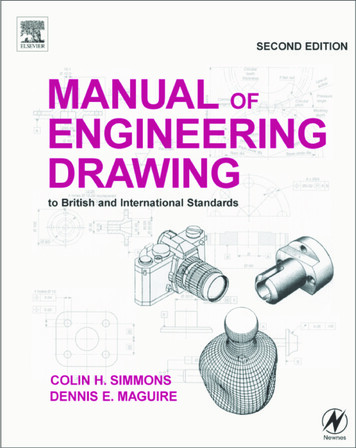
2Manual of Engineering Drawingpresented by a designer in the form of rough freehandsketches, may be developed stage by stage into workingdrawings by the draughtsman. There is generally verylittle constructive work which can be done by otherdepartments within the firm without an approveddrawing of some form being available. The drawing isthe universal means of communication.Drawings are made to an accepted standard, and inthis country, is BS 8888, containing normative andinformative references to international standards. Thesestandards are acknowledged and accepted throughoutthe world.The contents of the drawing are themselves, whereapplicable, in agreement with separate standards relatingto materials, dimensions, processes, etc. Largerorganizations employ standards engineers who ensurethat products conform to British and also internationalstandards where necessary. Good design is often theproduct of teamwork where detailed consideration isgiven to the aesthetic, economic, ergonomic andtechnical aspects of a given problem. It is thereforenecessary to impose the appropriate standards at thedesign stage, since all manufacturing instructionsoriginate from this point.A perfect drawing communicates an exactrequirement, or specification, which cannot bemisinterpreted and which may form part of a legalcontract between supplier and user.Engineering drawings can be produced to a goodprofessional standard if the following points areobserved:the types of lines used must be of uniformthickness and density;(b) eliminate fancy printing, shading and associatedartistry;(c) include on the drawing only the information whichis required to ensure accurate clear communication;(d) use only standard symbols and abbreviations;(e) ensure that the drawing is correctly dimensioned(adequately but not over-dimensioned) with nounnecessary details.23456(a)Remember that care and consideration given to smalldetails make a big contribution towards perfection,but that perfection itself is no small thing. An accurate,well delineated engineering drawing can give thedraughtsman responsible considerable pride and jobsatisfaction.The field of activity of the draughtsman may involvethe use, or an appreciation, of the following topics.1 Company communications Most companies havetheir own systems which have been developed overa period of time for the following:(a) internal paperwork,(b) numbering of drawings and contracts,(c) coding of parts and assemblies,(d) production planning for component manufacture,78(e) quality control and inspection,(f) updating, modification, and reissuing ofdrawings.Company standards Many drawing offices usetheir own standard methods which arise fromsatisfactory past experience of a particular productor process. Also, particular styles may be retainedfor easy identification, e.g. certain prestige carscan be recognized easily since some individualdetails, in principle, are common to all models.Standards for dimensioning Interchangeability andquality are controlled by the application of practicallimits, fits and geometrical tolerances.Material standardsPhysical and chemicalproperties and non-destructive testing methods mustbe borne in mind. Note must also be taken ofpreferred sizes, stock sizes, and availability of rod,bar, tube, plate, sheet, nuts, bolts, rivets, etc. andother bought-out items.Draughting standards and codes of practiceDrawings must conform to accepted standards, butcomponents are sometimes required which inaddition must conform to certain local requirementsor specific regulations, for example relating to safetywhen operating in certain environments orconditions. Assemblies may be required to beflameproof, gastight, waterproof, or resistant tocorrosive attack, and detailed specifications fromthe user may be applicable.Standard parts are sometimes manufactured inquantity by a company, and are used in severaldifferent assemblies. The use of standard partsreduces an unnecessary variety of materials andbasically similar components.Standards for costs The draughtsman is oftenrequired to compare costs where different methodsof manufacture are available. A component couldpossible be made by forging, by casting, or byfabricating and welding, and a decision as to whichmethod to use must be made. The draughtsmanmust obviously be well aware of the manufacturingfacilities and capacity offered by his own company,the costs involved when different techniques ofproduction are employed, and also an idea of thelikely costs when work is sub-contracted to specialistmanufacturers, since this alternative often provesan economic proposition.Data sheets Tables of sizes, performance graphs,and conversion charts are of considerable assistanceto the design draughtsman.Figure 1.1 shows the main sources of work flowinginto a typical industrial drawing office. The drawingoffice provides a service to each of these sources ofsupply, and the work involved can be classified asfollows.1 Engineering The engineering departments areengaged on(a) current production;
Drawing office management and organization(f) drawings resulting from value analysis andworks’ turingunitsFig. 1.1(b) development;(c) research;(d) manufacturing techniques, which may includea study of metallurgy, heat-treatment, strengthof materials and manufacturing processes:(e) advanced project planning;(f) field testing of products.2 Sales This department covers all aspects ofmarketing existing products and market researchfor future products. The drawing office may receivework in connection with(a) general arrangement and outline drawings forprospective customers;(b) illustrations, charts and graphs for technicalpublications;(c) modifications to production units to suitcustomers’ particular requirements;(d) application and installation diagrams;(e) feasibility investigations.3 Service The service department provides a reliable,prompt and efficient after-sales service to thecustomer. The drawing office receives workassociated with(a) maintenance tools and equipment;(b) service kits for overhauls;(c) modifications to production parts resulting fromfield experience;(d) service manuals.4 Manufacturing units Briefly, these cover alldepartments involved in producing the finished endproduct. The drawing office must supply charts,drawings, schedules, etc. as follows:(a) working drawings of all the company’sproducts;(b) drawings of jigs and fixtures associated withmanufacture;(c) plant-layout and maintenance drawings;(d) modification drawings required to aidproduction;(e) reissued drawings for updated equipment;Figure 1.2 shows the organization in a typical drawingoffice. The function of the chief draughtsman is totake overall control of the services provided by theoffice. The chief draughtsman receives all work cominginto the drawing office, which he examines anddistributes to the appropriate section leader. The sectionleader is responsible for a team of draughtsmen ofvarious grades. When work is completed, the sectionleader then passes the drawings to the checking section.The standards section scrutinizes the drawings to ensurethat the appropriate standards have been incorporated.All schedules, equipment lists and routine clerical workis normally performed by technical clerks. Completedwork for approval by the chief draughtsman is returnedvia the section leader.Since drawings may be produced manually, or byelectronic methods, suitable storage, retrieval andduplication arrangements are necessary. Systems incommon use include:(a)filing by hand into cabinets the original masterdrawings, in numerical order, for individualcomponents or contracts;(b) microfilming and the production of microfiche;(c) computer storage.The preservation and security of original documents isof paramount importance in industry. It is not smenCheckersFinished drawingsSales3TraineesDrawing office libraryReprographic sectionManufacturingunitsFig. 1.2SalesServiceDevelopment
4Manual of Engineering Drawingpractice to permit originals to leave the drawing office.A drawing may take a draughtsman several weeks todevelop and complete and therefore has considerablevalue. The reprographic staff will distribute copies whichare relatively inexpensive for further planning,production and other uses. A library section willmaintain and operate whatever archive arrangementsare in operation. A large amount of drawing officework comes from continuous product development andmodification so easy access to past designs and rapidinformation retrieval is essential.Engineering drawingpracticesThe comments so far refer to drawing offices in generaland typical organizational arrangements which are likelyto be found within the engineering industry. Goodcommunication by the use of drawings of quality relieson ensuring that they conform to established standards.BS 5070, Parts 1, 3 and 4 dealing with engineeringdiagram drawing practice, is a companion standard toBS 8888 and caters for the same industries; it providesrecommendations on a wide variety of engineeringdiagrams. Commonly, as a diagram can be called a‘drawing’ and a drawing can be called a ‘diagram’, itis useful to summarize the difference in the scopes ofthese standards. BS 8888 covers what are commonlyaccepted to be drawings that define shape, size andform. BS 5070 Parts 1, 3 and 4 covers diagrams thatare normally associated with flow of some sort, andwhich relate components (usually indicated by symbols)functionally one to another by the use of lines, but donot depict their shape, size or form; neither may theyin general indicate actual connections or locations.Therefore, any drawing or diagram, whetherproduced manually or on computer aided draughtingequipment, must conform to established standards andwill then be of a satisfactory quality for commercialunderstanding, use and transmission by electronic andmicrofilming techniques. All of the examples whichfollow conform to the appropriate standards.perform a much more effective role in the design processand many examples of its ability follow—but it willnot do the work on its own. The input by thedraughtsman needs to follow the same standards appliedin the manual method and this fact is often notunderstood by managers hoping to purchase CAD andobtain immediate answers to design enquiries. Thedraughtsman needs the same technical appreciation asbefore plus additional computing skills to use the variedsoftware programs which can be purchased.To introduce CAD an organization must set out clearobjectives which are appropriate to their present andfuture requirements and Fig. 1.3 includes aspects ofpolicy which could appear in such plans. The followingneed consideration:(a) CAD management roles;(b) creation, training and maintenance of capableCAD operators;(c) CAD awareness of design project team membersin addition to their leaders;(d) the flow of work through the system and theselecting of suitable types of project;(e) associated documentation;(f) possible changes to production methods;(g) needs involving the customer;(h) system needs relating to planning, security andupgrading;(i) CAD library and database (Storage of drawings,symbols, etc.) and archive procedures.Many similar aspects will be appropriate in particularapplications but good intentions are not sufficient. It isnecessary to quantify objectives and provide dates,deadlines, numbers, individual responsibilities andbudgets which are achievable if people are to bestretched and given incentive after full consultation.Present lines of communication will probably need tobe modified to accommodate CAD, and planningintegration is vital. A possible approach here is theappointment of a CAD Director with the ultimateresponsibility for CAD technology assisted by a SystemsManager and an Applications Manager.FeedbackDrawing practice and thecomputer (CAD: Computeraided draughting anddesign)The computer has made a far bigger impact on drawingoffice practices than just being able to mimic thetraditional manual drawing board and tee squaretechnique. However, it depends on drawing officerequirements and if only single, small, two dimensionaldrawings and sketches are occasionally required, thenthere may be no need for change. CAD can howeverCompany application.Design, manufacturing, sales and serviceCompanycomputer strategyand policy for 5year termOrganizationand methodsImplementation andcommunicationsystems for allusersHardwareSoftwareResourcesFig. 1.3General computer policy relationshipsPerformancemonitoringand control
Drawing office management and organizationA CAD Director has the task of setting andimplementing objectives and needs to be in a positionto define binding policy and direct financial resources.He will monitor progress. A Systems Manager has therole of managing the computer hardware, the softwareand the associated data. Company records and designsare its most valuable asset. All aspects of security arethe responsibility of the Systems Manager. Securitydetails are dealt with in the next chapter. TheApplications Manager is responsible for day to dayoperations on the CAD system and the steady flow ofwork through the equipment. He will probably organizetraining for operators in the necessary computer skills.Both of these managers need to liaise with the designproject leaders to provide and maintain a draughtingfacility which is capable of increasing productivity toa considerable degree.Figure 1.4 shows the probable position of the CADDirector in the management structure. His departmentwill be providers of computer services to all othercomputer users within the company.Managing rSystemsManagerFig. 1.4Why introduce BS 8888and withdraw BS 308?For 73 years, BS 308 was a highly regarded drawingoffice practice document. Why the change and whatwas behind the decision to withdraw BS 308 and replaceit with BS 8888?A drawing standardFrom time immemorial, drawings have been the mediumused to convey ideas and intentions. Hence the adagethat ‘a picture is worth a thousand words’. No need forlanguage, the picture tells it all. In recent years therehas, unfortunately, developed another opinion sinceCAD appeared on the scene, that there is no need fora draughtsman now as the computer does it all. Thetruth of the matter is that the computer is able to extendthe range of work undertaken by the draughtsman andis really a very willing slave. The evolution of theIndustrial Revolution required the ‘pictures’ to be moredetailed. In the pre-mass-production era, manufacturewas based on ‘matched fits’, with the assistance ofverbal communication. The advent of mass production5however, demanded more specific and precisespecifications.A national form of draughting presentation wasneeded to promote a common understanding of theobjectives and in September 1927, BS 308 came tofruition, as the recognized National Code of Practicefor Engineering Drawing.The initial issue was A5-size and contained only 14clauses. Dimensioning was covered in four paragraphsand tolerancing in only one. The recommendationswere based on just two example drawings. The recommended projection was first angle.RevisionsThe life span of BS 308 was 73 years and five revisionswere made. The first in December 1943, followed byothers in 1953, 1964, 1972 and 1985. The 1972 revisionwas a major one, with the introduction of three separateparts replacing the single document:The fifth (1985) revision replaced the Imperialstandard with a Metric edition.BS 308 was finally withdrawn and replaced by BS8888 in 2000. The revisions were necessary to keepabreast of technological innovations.As manufactured products became more sophisticatedand complex, the progress and development ofmanufacturing and verification techniques accelerated.Advances in the electronics industry ensured moreapplications in manufacturing with a very high degreeof sophistication. Much progress was also made sincethat single paragraph in the original 1927 versionrelating to tolerancing, together with the four paragraphsand the two examples covering dimensioning. Geometrical tolerancing was not referred to at all in earlyversions. The subject gained prominence during the1960s, especially when it was realized that a symboliccharacterization would assist in the understanding ofthe subject by users and replace the use of lengthynotes relating to geometric controls.This activity was addressed by the major revisionin 1972 with the publication of Part 3, devoted entirelyto the dimensioning of geometric tolerancing.The replacement of BS 308Formerly, the Chief Designer and the drawing officeset, and were responsible for, company manufacturingstandards and procedures, for other disciples to follow.This practice gradually eroded away because of theadvancement of progressive and sophisticatedtechniques in the manufacturing and verification fields.Increasing commercial pressure for Design forManufacture and Design for Inspection, created thedemand for equal status. During the period separatestandards were gradually developed for design,manufacture and measurement. Each discipline utilized
6Manual of Engineering Drawingsimilar terms but often with slightly differentinterpretations despite their apparent commonality.An urgent need to harmonize the meaning of theseterms was recognized by ISO. An international meetingin 1989 formed a Joint Harmonization Group.The Danish Standards Association funded a projectto bring all design, measurement, and metrologystandards together using definitions common
Aug 15, 2000 · Engineering Drawing Second edition Colin H Simmons I.Eng, FIED, Mem ASME. Engineering Standards Consultant Member of BS. & ISO Committees dealing with Technical Product Documentation specifications Formerly Standards Engineer, Lucas CAV. Dennis E Maguire CEng. MIMechE, Mem