Transcription
MICROBRITE COLOR AND WHITE LED LIGHTFOR POOL AND SPAINSTALLATIONANDUSER’S GUIDEIMPORTANT SAFETY INSTRUCTIONSREAD AND FOLLOW ALL INSTRUCTIONSSAVE THESE INSTRUCTIONS
iiTechnical SupportPhone: (800) 831-7133 - Fax: (800) 284-4151Web sites: www.pentairpool.com and www.staritepool.com:ContentsIMPORTANT WARNING AND SAFETY INSTRUCTIONS. iiiMicroBrite Color and White Pool Light Overview .1Operating MicroBrite Lights Using a Wall Switch .1Operating MicroBrite Lights Using an Automation System .1Using and External Transformer for Multiple 12 VAC MicroBrite .1Maximum Wattage Using Multiple Color or White Lights(with a 300 Watt Isolation Transformer) .1Operating MicroBrite Color Lights Using a Wall Switch.2Powering on the MicroBrite Color Lights .2Selecting a MicroBrite Light Color and Show Modes or Fixed Colorusing a Wall Switch .3Saving a Color Mode or Fixed Color .3MicroBrite White Light .3Power on the MicroBrite White Light.3Selecting a MicroBrite White Light Brightness Level using a Wall Switch.3Selecting a MicroBrite Color Light Show ModeUsing an IntelliBrite Controller .4MicroBrite Light Installation (1.5” Wall Fittings, New Pool - USA).5MicroBrite Light Installation (1.5” Wall Fittings, New Pool - Canada).6WET CONDUIT INSTALLATION . 7MicroBrite Light Compatible Wall Fittings Table .7DRY/SEALED CONDUIT INSTALLATION (USE PROVIDED KIT) . 10Fiber Optic Retrofit Applications .11MicroBrite Color and White Light Wiring Installation .11Replacing the MicroBrite Light Assembly (in an existing pool or spa) .13Connecting MicroBrite Lights to EasyTouch/IntelliTouch Load Center .15Setting up MicroBrite Lights with EasyTouch/IntelliTouch AutomationSystem. 16Wiring MicroBrite Lights to IntelliBrite Controller and 300 W Transformer.20Troubleshooting (MicroBrite Lights / IntelliBrite Controller) .20MicroBrite Color and White Lights Parts List .21MicroBrite Color and White Lights Replacement Kits .21MicroBrite Color and White Light Dimensions .22READ AND FOLLOW ALL INSTRUCTIONS IN THIS MANUALP/N 523371 Rev. A 4/2018MicroBrite Color and White Light Installation and User’s Guide
iiiIMPORTANT WARNING AND SAFETY INSTRUCTIONSSERIOUS BODILY INJURY OR DEATH CAN RESULT IF THIS LIGHTIS NOT INSTALLED AND USED CORRECTLY.INSTALLERS, POOL OPERATORS AND POOL OWNERS MUSTREAD THESE WARNINGS AND ALL INSTRUCTIONS BEFOREUSING THE POOL AND/OR SPA LIGHT.Most states and local codes regulate the construction, installation, andoperation of public pools and spas, and the construction of residentialpools and spas. It is important to comply with these codes, many of which directlyregulate the installation and use of this product. Consult your local building and healthcodes for more information.IMPORTANT NOTICE - Attention Installer: This Installation and User’sGuide (“Guide”) contains important information about the installation, operationand safe use of this underwater pool and spa light. This Guide should be givento the owner and/or operator of this equipment.Before installing this product, read and follow all warning noticesand instructions in this Guide. Failure to follow warnings andinstructions can result in severe injury, death, or property damage.Call (800) 831-7133 for additional free copies of these instructions. Please refer to www.pentairpool.com for more information related to this products.RISK OF ELECTRICAL SHOCK OR ELECTROCUTION:UNDERWATER POOL LIGHTS REQUIRE HIGH VOLTAGE WHICHCAN SHOCK, BURN, OR CAUSE DEATH.Before working or servicing pool lights, always disconnectpower to the pool and/or spa lights at the source circuitbreaker. Failure to do so could result in death or serious injuryto service person, pool users or others due to electric shock.When installing and using this electrical equipment, basicsafety precautions should always be followed.This product must be installed by a licensed or certified electrician or a qualifiedpool professional in accordance with the current National Electrical Code (NEC),NFPA 70 or the Canadian Electrical Code (CEC), CSA C22.1. All applicable localinstallation codes and ordinances must also be adhered to. Improper installationwill create an electrical hazard which could result in death or serious injury to poolusers, installers or others due to electrical shock, and may also cause damage topower source. Always disconnect the power to the pool light at the circuit breakerbefore installing or removing the light. Failure to do so could result in death orserious injury.For countries in compliance with International ElectrotechnicalCommission (IEC) regulatory standards: The light fixture mustbe installed by a licensed or certified electrician or a qualified pool service person, inaccordance with current IEC 364-7-702 and all applicable local codes and ordinance.Improper installation will create an electrical hazard, which could result in death or seriousinjury to pool user, installer or other due to electrical shock and may also cause damageto the property.MicroBrite Color and White Light Installation and User’s Guide
ivIMPORTANT WARNING AND SAFETY INSTRUCTIONSINSTALLERS AND INSPECTORSTHE MICROBRITE COLOR AND WHITE LED LIGHT AND WALL FITTINGFORM A COMPLETE NON-METALLIC LOW VOLTAGE LIGHTING SYSTEM.THIS CONFIGURATION DOES NOT REQUIRE BONDING OR GROUNDINGWHEN POWERED BY A POOL RATED ISOLATION 100 WATT OR 300 WATTTRANSFORMER (LISTED ON PAGE 1) AND INSTALLED IN COMPLIANCE WITHTHE CURRENT NATIONAL ELECTRIC CODE (NEC).UNBONDED LIGHTING NEC PROVISIONS: When the UL listed non-metallicMicroBrite Light low voltage lights are used. The current NEC provides anexception to luminaire bonding and grounding in Article 680.6 and 680.23POOL WATER BONDING NEC PROVISIONS : For Pool Water Bonding required byNEC Article 680.26C, concrete pools are considered conductive (refer to 680.26(b)(1) due to the porosity of concrete and the bonding of rebar. No additionalbonding is required.POOL AND SPA FIXED LUMINARIES: Follow these guidelines when installing orreplacing Pentair Water Pool and Spa fixed luminaries:FOR LIGHT OPERATION, ONLY USE A SAFETY ISOLATION TRANSFORMER.Note: Connect both wires to the corresponding circuit wires in the JunctionBox (black wire to power, and white wire to common) FIXED POOL AND SPALUMINARIES SPECIFICATION: 12 VAC 50/60 Hz.IMPORTANT NOTICE: THE MICROBRITE COLOR AND WHITE LEDLIGHT IS A NON-SERVICEABLE LIGHT. THE COMPLETE LIGHTASSEMBLY MUST BE REPLACED.CAUTION - DO NOT INSTALL MICROBRITE COLOR ANDWHITE LED LIGHTS WITH DIMMER SWITCHES. USE OF DIMMERSWITCHES WILL RESULT IN PERMANENT DAMAGE TO THELIGHT.MicroBrite Color and White LED Lights are UL Approvedto be installed in a vertical position (facing up). Vertical lightinstallation must be installed minimum 4 inches below waterlevel.Vertical Light installations are recommended only innon-occupant areas of the pool (e.g. up-lighting a vanishingedge overspill).MicroBrite Color and White Light Installation and User’s Guide
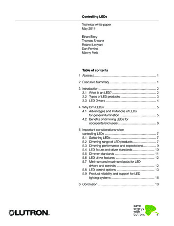
1MicroBrite Color and White LED Light OverviewThis manual describes how to install, replace and operate the 12 VAC MicroBrite Colorand White Light for pool and spa. The MicroBrite Color light provides brilliant vividmulti-colors with spectacular effects for your pool. Choose one of the seven preprogrammed color light shows or select one of the five fixed colors to create virtuallyendless range of dramatic underwater lighting effects for a spectacular effect in your pooland spa. The 12 VAC MicroBrite White Light features three different brightness levels. Formore information see page 2.Operating MicroBrite Lights Using a Wall SwitchThe MicroBrite light can be manually controlled using a standard wall-mount light switch.Multiple MicroBrite lights can be connected via a junction box and a 12 VACisolation transformer to a single switch so that all lights can be switched on and offtogether. For wiring diagram, see page 15.Operating MicroBrite Lights Using an Automation SystemMicroBrite color lights can also be automatically controlled using the Pentair IntelliTouch and EasyTouch Control System. For more information refer to the IntelliTouchControl System User’s Guide (P/N 521075), EasyTouch Control System User’s Guide(P/N 521044), and IntelliBrite 5G Light User’s Guide (P/N 619921).Using an External Safety Isolation Transformer for Multiple 12 VACMicroBrite LightsWhen using multiple MicroBrite 12 VAC lights on a 100 Watt safety isolation transformer, itis recommended that no more than six (6) MicroBrite color lights be used. For long cablelengths for each light, It is recommended not to exceed 45.72 m (150 ft.) of total cable runbetween the 12 VAC isolation transformer and the MicroBrite Color and/or White light.100 WattTransformer12 Gauge(minimum)J Box45.72 m(150 ft.)Note: If a longer cablerun is necessary, it isrecommended thatseparate 100 Watt safetyisolation transformers beused for each light withno more than 45.72 m(150 ft.) of total cable runbetween the transformerand lights.Maximum Wattage Using Multiple Color or White lights(with a 300 Watt Isolation Transformer)IMPORTANT! When using multiple 12 VAC Pentair pool and spa lights the total allowablelight wattage is 300 Watts maximum and should not exceed 80% of rated value. Theindividual light wattage is as follows: One MicroBrite Color Pool LED light is 12 Watts maximum One MicroBrite White Pool LED light is 12 Watts maximum One AmerBrite White (500W) pool light is 51 Watts maximum One AmerBrite White (400W) pool light is 44 Watts maximum One AmerBrite White (300W) pool light is 36 Watts maximum One AmerBrite Color pool light is 36 Watts maximum One IntelliBrite Color pool LED light is 30 Watts maximum One IntelliBrite Color spa LED light is 18 Watts maximumMicroBrite Color and White Light Installation and User’s Guide
2Operating MicroBrite Color LED Light using a Wall SwitchMicroBrite Color Lights can be controlled using a standard wall-mount light switch (or bythe IntelliBrite Controller, see page 4). Multiple MicroBrite color lights can be connectedvia a junction box and a 12 VAC transformer to a single switch so that all lights can beswitched on and off together. MicroBrite color lights are controlled by cycling AC powerto the 12 VAC transformer from a standard wall switch. By turning the switch on and offa specific number of times, the light activates one of the seven light show modes, fixedcolors, or enables the “Hold” and “Recall” feature.Powering on the MicroBrite Color LightsWhen the MicroBrite color light is powered on, the previously selected color is displayed,unless the HOLD or RECALL feature was previously enabled.Note: If power to the light is off for more than five (5) seconds, the last color show mode orfixed color that was saved will be displayed.Selecting a MicroBrite Color Light Show Mode or Fixed Color using a WallSwitchNumber of times to cycle power (1-14)MicroBrite color lights are compatible with IntelliBrite Color Light shows and can besynchronized with IntelliBrite color lights.First switch power on to the light. A white light will momentarily illuminate, followed by thepreviously selected color. To select a color show mode (1-7) or fixed color(8-12), turn the wall switch off/on a specific number of times. Each number (1-12) shownbelow corresponds to the number of times to power-cycle the switch to activate a colorlight show or fixed color. For details about saving color effects while in “show” modes, see“Hold” and “Recall” feature on page 4.1 SAm Mode: Cycles through white, magenta, blue and green colors(emulates the Pentair SAm color changing light).2 Party Mode: Rapid color changing building energy and excitement.3 Romance Mode: Slow color transitions creating a mesmerizing andcalming effect.4 Caribbean Mode: Transitions between a variety of blues and greens.5 American Mode: Patriotic red, white and blue transition.6 California Sunset Mode: Dramatic transitions of orange, red andmagenta tones.7 Royal Mode: Richer, deeper color tones.8 Blue: Fixed color.9 Green: Fixed color.10 Red: Fixed color.11 White: Fixed color.12 Magenta: Fixed color.13 Hold: Save the current color effect during a color light show.14 Recall: Activate the last saved color effect.Example: To select California Sunset Mode; turn the switch on, then off and on six (6)times. During the off/on switching process, no illumination will occur, then a white light willmomentarily illuminate.WARNING During the off/on switching process, before the selected color is displayed, no illuminationwill occur. This operating mode is normal during the switching process. During this period the pool and spawill be dark and precautions should be taken to avoid unforeseen accidents. Failure to observe thiswarning may result in serious injury or death to pool and spa users.MicroBrite Color and White Light Installation and User’s Guide
3Saving a Color Mode or Fixed ColorWhen power is switched off to the MicroBrite Color Lights, the last color show mode orfixed color will be saved. The next time the light is powered on, the previously saved colorshow mode or fixed color will be displayed. For example, while in “Party Mode” switch thelight off. Wait more than five (5) seconds, switch the light back on to resume Party Mode.MicroBrite White LightMicroBriteWhite Lights can be controlled using a standard wall-mount light switch.Multiple MicroBrite white lights can be connected via a junction box and a 12 VAC transformer to a single switch so that all lights can be switched on and off together. MicroBriteWhite lights are controlled by cycling AC power to the 12 VAC transformer from a standard wall switch. By turning the switch on and off a specific number of times, you canchoose from one of three brightness levels.Powering on the MicroBrite White LightNote: The MicroBrite White light ships from the factory in the 100% brightness mode.When the MicroBrite White light is powered on, it defaults to the previously selectedbrightness level. Note: If power to the light is off for more than five (5) seconds, the lastbrightness level that was saved will be displayed.Selecting a MicroBrite White Light Brightness Level using a Wall SwitchMicroBrite White lights allow you to choose from one of three brightness levels (100%,75% and 50%). Whenever the MicroBrite white light is turned on, it starts at its highestbrightness level (100%). Unless it was previously set to the medium (75%) or lowbrightness level (50%).NOTE: MicroBrite Color models are not equipped with dimming functionality. OnlyMicroBrite White lights have dimming functionality.To select one of the three brightness levels (100%, 75% and 50%) first power on thelights, then by rapidly cycling the light switch OFF and ON a specified number of times,you can select the desired light brightness level.Selecting the light’s brightness levels is as follows: 100% Brightness: Switching the lights OFF then rapidly back ON, will setthe lights to 100% brightness. 75% Brightness: Switch OFF-ON-OFF-ON 50% Brightness: Switch OFF-ON-OFF-ON-OFF-ON and the lights willcome on at 100%, dim to 75% after one second and then dim to 50% afteranother second.100% them dim to 75% after 1 second.and the lights will come on atMicroBrite Color and White Light Installation and User’s Guide
4Selecting Color and Show Modes using an IntelliBrite ControllerThe MicroBrite Color light can be controlled with the IntelliBrite Controller (p/n600054, sold separately). The IntelliBrite Controller provides complete control of yourMicroBrite color lights. Just dial in any one of the pre-programmed color light shows orfixed colors. The IntelliBrite Controller can be connected to individual or multiple12 VAC transformers (300W maximum) to control MicroBrite color lights. The IntelliBriteController can also control multiple MicroBrite and IntelliBrite lights. Note: ForIntelliBrite controller wiring instructions, see page 19.Using the IntelliBrite Controller: MicroBrite colorlights are compatible with IntelliBrite colors andshows and can be synchronized with IntelliBrite colorlights and landscape lights. To select a color lightshow mode or fixed color mode, rotate the dial sothat it points to the desired selection. The color modeselections start in a clockwise direction from the 9o’clock position.Hold and Recall FeatureHold button/LED: Press this button (LED on) tocapture and save a color effect while displaying one ofthe light show modes. When the button is pressed, the LED will be on, indicating that thecolor effect is captured.Recall Button/LED: Use this button (LED on) to activate the last saved color effect. Whenthe button is pressed, the LED will be on, indicating that the color effect is being displayed.MicroBrite Color and White Light Installation and User’s Guide
5MICROBRITE COLOR AND WHITE LED LIGHTINSTALLATION IN 1.5” WALL FITTINGThe following describes how to install the MicroBrite Light in a 1-1/2” wall fitting.Note: MicroBrite lights are UL compliant for horizontal and vertical installation.BEFORE STARTING: The following information describes the tasks thatmust be completed by the electrician before the light wall fitting is installed.See Figure 1 on page 7.Be sure that the pool or spa meets the requirements of the current National ElectricalCode (N.E.C.) Article 680-22 and all local codes and ordinances. A licensed orcertified electrician must install the electrical system to meet or exceed thoserequirements before the underwater light is installed. Some of the requirements of theNational Electrical Code which the pool’s electrical system must meet are as follows: The Junction Box and the low voltage transformer is located at least4 (four) inches (10.16 cm) above ground level or eight (8) inches(20.3 cm) above maximum water level, whichever is higher. The Junction Boxmust be at least 48 inches (1.22 m) from the edge of the pool. See Figure 2 onpage 8. To be certain that the pool or spa electrical system meets all applicablerequirements, the electrician should also consult the local building department.Wall Fitting: 3.81 cm (1.5 in) PVC PipeFor Gunite OnlyNOTE: MicroBrite Ligths are UL Approved to be installed ina vertical position (facing up). Vertical light installation mustbe installed minimum 4 inches below water level.Vertical Light installations are recommended only innon-occupant areas of the pool (e.g. up-lighting avanishing edge overspill).Figure 1.NOTE: SEE PAGE 21 FOR LIGHT DIMENSIONS.MicroBrite Color and White Light Installation and User’s Guide
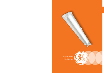
6MICROBRITE COLOR AND WHITE LED LIGHTINSTALLATION IN 1.5” WALL FITTING CANADABe sure the electrical system of your pool conforms with the following requirementsof the Canadian Electrical Code (CE), and all local codes and ordinances. A licensedor certified electrician must install the electrical system to meet or exceed thoserequirements before the light and (fixture-housing) is installed. Some of the CErequirements are listed below. The junction/deck box must be sealed to the conduit to prevent water fromgetting into the box, see Figure 2, below.The following information is for the Junction Box and pool deck location for Canada only.Junction/Deck boxes shall be installed:(a) above the normal water level of the pool;(b) so that the top of the box is located at or above the finished level of the pool deck;(c) in such a manner or location that the box will not be an obstacle; and(d) in such a manner that any water on the deck will drain away from the box(See diagram below).Deck water drainsaway from Junction/Deck BoxApproved Junction/Deck Boxelevated and protectedApproved Junction/Deck BoxDiving Board orother equipmentto protectJunction/Deck BoxWater levelbelow Junction/Deck BoxTop of Junction Box Flushwith DeckJunction/Desk Box elevated aboveDeck and ProtectedFigure 2, Canada.MicroBrite Color and White Light Installation and User’s Guide
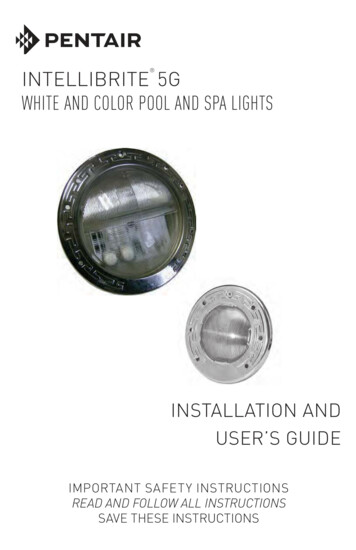
7MicroBrite Color and White LED Light InstallationCompatible Wall FittingsPart NoDescription Part irPentairSP1022Hayward 215-9170BWaterWay yCMP25550001060 CMPCMP25522100000 CMPCMP25550000000 CMPThe MicroBrite light adaptor allows the mounting of the MicroBrite Light in the 1-1/2”return fitting. Refer to the Compatible MicroBrite Light Wall Fittings table above.FOR FIBER OPTIC RETROFIT APPLICATIONS SEE PAGE 11.WET CONDUIT INSTALLATIONNote: MicroBrite lights are shipped from the factory with the white threaded adaptorring pre-installed onto the body of the light. The male threads on the white threadedadaptor ring allow the light to be threaded into the female threads of most 1-1/2”(1.5”) pool wall return fittings. To install the MicroBrite Light wall fitting into aconcrete/gunite pool:1. To install a MicroBrite Light, route the MicroBrite light power cord light cablethrough the 1.5” wall fitting to the location of the 12 VAC pool transformer orjunction box.2. Wrap plumber’s thread sealant tape around the male threads on the whitethreaded adaptor ring on the light.3. Pull the MicroBrite power cord through the conduit so there is approximatelythree to six inches of visible cord between the body of the MicroBrite light andthe wall fitting.Wrap threaded sealanttape around theadaptor1-1/2” StandardWall FittingContinue to Step 4 on next page.MicroBrite Color and White Light Installation and User’s Guide
8WET CONDUIT INSTALLATION (Continued)4. With the MicroBrite light in your hands, roll the body of the light several turnscounter-clockwise, so that the cord of the MicroBrite light receives several“pre-twists” in a counter-clockwise direction. Read Step 5 before continuing5.with Step 6.Dry/Sealed Conduit Installation (use provided kit), see page 10: Ifcode requires an O-Ring to be installed on the light for a dry conduitinstallation, install the O-Ring as described on page 10, then continuewith Step 6 below.BEFORE INSTALLATIONBy hand, turn light bodycounter-clockwise totwist cordCord should be twistedcounter-clockwise6. Insert the MicroBrite light into the 1.5” wall fitting. By hand start the process ofthreading the male threads on the MicroBrite’s white threaded adaptor ring into thefemale threads of the wall fitting.DURING INSTALLATIONBy hand turn light clockwise.Insert adaptor male threadadaptor ring into femalethread of wall fittingCord will un-twistas light is turnedclockwise into fittingMicroBrite Color and White Light Installation and User’s Guide
9WET CONDUIT INSTALLATION (Continued)7. Place Microbrite light installation tool (P/N 620459) over the front of the lightwhile turning the tool and light clockwise.Note: If the light does not turn smoothly, pull the light slightly out and be surethat it’s seated properly and the wall fitting is free of debris, then reinstall thelight.8. Turn the light clockwise while threading it into the wall fitting to un-twist thepower cord.9. Turn the light clockwise (approximately 5 turns) so that it is threaded tightly intothe wall fitting.10. Note: Once the light is tightly installed remove the tool be sure the lightcannot be unscrewed using your fiingers. The light should be secured inplace so that it can only be removed by using the light installation tool.Light Cable to Junction BoxInstallation Tool1-1/2” StandardWall FittingContinue to Light Wiring Installtion on page 11.MicroBrite Color and White Light Installation and User’s Guide
10DRY/SEALED CONDUIT INSTALLATION (USE PROVIDED KIT)1. Note: The the pool water level must be below the level of the 1.5” returnfitting where the MicroBrite will be installed.2. Follow the Wet Conduit Installation Steps 1-10 as described on page 7, 8 and 9.At Step 4, be sure to install the Optional O-Ring onto the back of theMicroBrite light.3. Pull the O-Ring over the front of the light lens and place it behind the lens body.4. Apply the provided lubricant on the O-Ring.5. By hand, press the light body into the wall fitting until the O-Ring is seatedinside the wall fitting.6. Resume the installation process at Step 6 (see page 8).Install O-Ring then applyprovided lubricant toseal fitting and conduitfrom water entry1-1/2” StandardWall FittingAdaptorMicroBrite Color and White Light Installation and User’s Guide
11FIBER OPTIC RETROFIT APPLICATIONSThe MicroBrite Light may be suitable for many fiber optic retrofit applications.IMPORTANT:1. Before proceeding with the fiber optic retrofit installation, verify that theMicroBrite light fits properly before removing the fiber optic system.2. Refer to the MicroBrite light dimensional drawings on page 21.3. Read all instructions to verify that all of the 1.5” fittings in the pool havesuitable dimensions to allow the MicroBrite light to fit properly.4. Be sure the conduit that was previously utilized as housing for the fiberoptic cables meets all applicable codes and regulations that apply toelectrical conduit in swimming pool applications.MicroBrite Color and White LED Light Wiring InstallationTo connect the MicroBrite Light to the transformer or junction box:1. Route the MicroBrite light power cord light cable through the wall fitting to thelocation of the 12 VAC pool transformer or junction box.2. At the 12 VAC transformer or junction box, cut off any extra cord. Leave atleast 15.2 cm (6 in) of cord in the Junction Box or transformer to facilitatethe light installation wall fitting inspection. Cut off any extra cord.See Figure 1 on page 5, for junction box installation for USA, see Figure 2on page 6 for junction box installation in Canada.3. Connect the two (2) conductors to the corresponding circuit wires in the JunctionBox. Secure the Junction Box cover.Note: When using longer runs of cables or multiple lights per transformer,it is recommended to use the 13 VAC or 14 VAC tap on the transformer.4. Before operating the MicroBrite light, fill the pool with water until the light iscompletely submerged.Note: The MicroBrite color light should not be powered for more than 30seconds if is not submerged in water.5Final check for proper MicroBrite light operation:Switch on the main switch or circuit breaker to the 12 VAC transformer and theswitch that operates the MicroBrite light itself. The light should illuminate whenthe 12 VAC power is applied. If not recheck the installation steps.MicroBrite Color and White Light Installation and User’s Guide
12REPLACING THE MICROBRITE COLOR ANDWHITE LED LIGHT ASSEMBLY (IN AN EXISTING POOL OR SPA)Risk of Electrical Shock or Electrocution!This underwater light must be installed by a licensed or certifiedelectrician or a qualified pool professional in accordance withthe current National Electrical Code (NEC), NFPA 70 or theCanadian Electrical Code (CEC), CSA C22.1 and all applicablelocal codes and ordinances. Improper installation will create anelectrical hazard which could result in death or serious injury topool users, installers or others due to electrical shock, and mayalso cause damage to property.Always disconnect the power to the pool light at the circuitbreaker before servicing the light. Failure to do so could resultin death or serious injury to service person, pool users or othersdue to electrical shock.IMPORTANT NOTICE: THE MICROBRITE COLOR AND WHITE LEDLIGHT IS A NON-SERVICEABLE LIGHT. THE COMPLETE LIGHTASSEMBLY MUST BE REPLACED.Verify that the pool and spa meets the requirements of the current NationalElectrical Code and all local codes and ordinances. A licensed or certifiedelectrician must install the electrical system to meet or exceed thoserequirements before the underwater light is installed. Some of the requirementsof the National Electrical Code which the pool’s electrical system must meet areas follows: The Junction Box and the low voltage transformer is located at least4 (four) inches (10.16 cm) above ground level or eight (8) inches(20.3 cm) above maximum water level, whichever is higher. The Junction Boxmust be at least 48 inches (123 cm) from the edge of the pool. See Figure 1on page 8. The MicroBrite light wall fitting must be properly installed so that the topedge of the lens of the MicroBrite light is at least 4 inches (10.16 cm) below(not more than 48 inches (123.cm) below in Canada) the surface of the waterin the pool or spa. See Figure 1 on page 8. To be certain that the pool or spa electrical system meets all applicablerequirements, the electrician should also consult the local buildingdepartment.MicroBrite Color and White Light Installation and User’s Guide
13IMPORTANT NOTICE:THE MICROBRITE COLOR AND WHITE LED LIGHT IS ANON-SERVICEABLE LIGHT. THE COMPLETE LIGHT ASSEMBLYThe following removal and installation instructions describe how to remove and install theMicroBrite light
(P/N 521044), and IntelliBrite 5G Light User's Guide (P/N 619921). Using an External Safety Isolation Transformer for Multiple 12 VAC MicroBrite Lights When using multiple MicroBrite 12 VAC lights on a 100 Watt safety isolation transformer, it is recommended that no more tha