Transcription
Auger DriveOperation and Maintenance ManualRevision Date: July 2017
Skid Pro AttachmentsPO Box 982Alexandria, MN 56308Toll Free: 877-378-4642www.skidpro.comCONTENTSSAFETY INSTRUCTIONS - READ CAREFULLY . 2Safety Precautions . 2HYDRAULIC SYSTEM HOOK-UP INSTRUCTIONS . 5MAXIMUM HYDRAULIC FLUID LINE PRESSURE . 5Maximum Hydraulic Fluid Flow per Unit . 5OPERATING INSTRUCTIONS . 6MAINTENANCE INSTRUCTIONS . 7Hydraulic Oil . 7Hydraulic Hose Assemblies . 7Auger and Drive . 7TROUBLESHOOTING . 8Slow Speed (rpm) or Insufficient Digging Power. 8Excessive Oil Heating . 8Oil Leaks . 8AUGER DRIVE DIAGRAMS AND PARTS LISTS . 9Decals . 9M Series Auger Drive - Set Up Assembly - Diagram A . 10M Series Auger Drive - Set Up Assembly – Parts List A . 10M Series Auger Drive - Planetary Gear Box - Diagram B . 11. 11M Series Auger Drive - Planetary Gear Box - Parts List B . 11NC Series Auger Drive - Set Up Assembly - Diagram A . 12NC Series Auger Drive - Set Up Assembly – Parts List A . 12NC Series Auger Drive - Planetary Gear Box, 2” Hex - Diagram B . 13NC Series Auger Drive - Planetary Gear Box, 2” Hex - Parts List B . 13SKID PRO ATTACHMENT WARRANTY . 14Skid Pro Auger ManualRev. 7:17Page1
THIS SAFETY ALERT SYMBOL IDENTIFIES IMPORTANT SAFETY WARNING MESSAGES. CAREFULLYREAD EACH WARNING MESSAGE THAT FOLLOWS. FAILURE TO UNDERSTAND AND OBEY ASAFETY WARNING, OR RECOGNIZE A SAFETY HAZARD, COULD RESULT IN AN INJURY OR DEATHTO YOU OR OTHERS AROUND YOU. THE OPERATOR IS ULTIMATELY RESPONSIBLE FOR THESAFETY OF HIMSELF, AS WELL AS OTHERS, IN THE OPERATING AREA OF AUGER.SAFETY INSTRUCTIONS - READ CAREFULLYThe use of this equipment is subject to certain hazards, which cannot be protected against by mechanical means orproduct design. All operators of this equipment must read and understand this entire manual, paying particular attentionto safety and operating instructions, prior to using the Skid Pro auger. If there is something in this manual you donot understand, ask your supervisor to explain it to you. Failure to observe these safety precautions can result indeath or serious injury or serious equipment damage.Do not take chances - be a careful operator. Read this manual thoroughly before attempting to operate the auger.Working with unfamiliar equipment can cause accidents. If after thoroughly reading this manual, you have anyquestions regarding safety or understanding the intended uses and the limitations of your Skid Pro auger, contactthe Skid Pro office or your authorized dealer. We will be more than happy to assist you in the proper use of thismachine. Be safety conscious.The safety of the operator is one of the prime considerations of Skid Pro. Shielding, adjustments, and other safetyfeatures were built into the machine wherever possible. The owner, operator, and person who is directly responsiblefor the operation of the auger must accept his responsibility for safe operation. With your cooperation, by not takingrisks, and understanding the manual in full, to know how to be careful, accidents can be prevented. If the personwho will operate this machine does not read or understand English, it is the owner's responsibility totranslate or provide an interpreter.You will find in this manual notes, warnings and cautions. This does not mean that the auger is dangerous. Nordoes it mean that they should be taken lightly. You must exercise the utmost care and caution in use of the auger,and realize that it is a powerful machine that can cause serious injury or death if improperly used. Hitching andremoving the auger, along with digging with other workmen present are the times you need to be extremelycautious.Safety PrecautionsTHIS MANUAL MUST BE READ AND UNDERSTOOD IN ITS ENTIRETY BEFOREATTEMPTING ANY ASSEMBLING, OPERATION, INSTALLATION, MAINTAINING ORREPAIRING OF THE AUGER. STRICTLY OBSERVE THE NOTES, CAUTIONS ANDWARNINGS NOTED THROUGHOUT THIS MANUAL.OPERATE AUGER ONLY FROM OPERATORSSEAT. KEEP ALL OTHERS AT LEAST 10 FEETAWAY.A careful operator is the best protection against accidents. Most accidents involvingoperators of equipment are listed on the following pages.Skid Pro Auger ManualRev. 7:17Page 2
1) Only the operator should be allowed on themachinery when the auger is in operation.Make sure they are instructed and capable ofsafeoperation.Carefullysuperviseinexperienced operators. Never allow childrento operate the auger.2)10) Travel only with the auger in a safe transportposition to prevent uncontrolled movement.Drive slowly over rough ground and onslopes. Tether auger with a chain, ifnecessary to prevent uncontrolled swinging ofauger when moving from hole to hole.Removeaugerfromvehiclewhentransporting to and from job site.Learn how to operate this machine in a safe,open area before operating in tight quarters orin conjunction with other equipment or people.11) Before exiting vehicle, lower auger to ground,turn off vehicle engine and lock vehiclebrakes.3) All bystanders should be kept a minimum of10 feet (3 meters) away from working area ofthe auger. Never operate the auger controlsfrom the ground. Always operate the vehicleand auger from the correct operating position.12) Do not work on or make any adjustments tothe tractor or auger while either is inoperation. Turn off tractor engine, lower augerto the ground and operate auger controllevers to relieve residual hydraulic pressurebefore adjustments or repairs are made, orwhen leaving the tractor. Do not leave theauger unattended with the auger raised.Always lower it to the ground.4) Always wear an OSHA approved hard hat andsafety eye protection when operating orservicing this equipment. Do not wear loosefitting clothing, flopping cuffs, danglingneckties and scarves, or rings and wristwatches that can catch moving parts.13) Never check a pressurized system for leakswith your bare hand. Oil escaping frompinhole leaks under pressure can penetrateskin and could cause serious infection. Hold apiece of cardboard up next to suspected leaksand wear a face shield or safety eyeprotection. If any fluid is injected into the skin,it must be removed within a few hours bydoctor familiar with this type of injury.5) An operator must not use drugs or alcoholwhich can change his alertness orcoordination. An operator taking prescriptionor over-the-counter drugs should seekmedical advice on whether or not he cansafely operate equipment.6)Always locate underground electrical wires,telephone cables, gas, water and sewer linesbefore digging. Maintain safe clearance andavoid contact with any underground oroverhead utility lines or electrically chargedconductors.14)Before disconnecting hydraulic lines orfittings be sure to relieve all pressure bycycling all hydraulic controls after shutdown.Remember hydraulic systems are underpressure whenever the engine is running andmay hold pressure after shutdown. Beforeapplying pressure to the system make sure allconnections are tight and that there is nodamage to lines, fittings and hoses.7) Never alter or remove any safety decals orshields. Replace all missing or damagedsafety decals or safety shields. Check thismanual for location of these items and replaceimmediately if damaged or illegible.15) Flow and pressure gauges, fittings and hosesmust have a continuous operating pressurerating of at least 25% higher than highestpressures of this system.8) Whenever changing or installing this or otherattachments, make sure all connections aresecurely fastened.16)Never adjust a relief valve for a pressurehigher than recommended by vehiclemanufacturer.9) Avoid steep hillside operation which couldcause the vehicle to overturn. Consult yourvehicle operator's and safety manuals formaximum incline allowable.17) When digging rocky soil, always wear safetyglasses.18) Always wear safety glasses and appropriateprotective gear when working on the auger,particularly when driving pins or teeth with ahammer.Skid Pro Auger ManualRev. 7:17Page 3
19) Never perform any work on an auger unlessyou are authorized - and qualified - to do so.Always read the operator service manual(s)before any repair is made. After completingmaintenance or repair, check for correctfunctioning of the auger. If not functioningproperly always tag "DO NOT OPERATE"until all problems are corrected20) Check the machine frequently to be surethere are no loose bolts. Be sure toimmediately tighten any loose nuts with theproper tools.21) Before digging or otherwise operating themachine, you should carefully inspect thearea to be worked, looking for and noting allgullies, or ditches, etc. and removing anyposts, trash, wire, and other obstacles orpotential hazards.22) This manual covers the safe use, installation,operation, and service instructions for theauger only. Always read the operating andsafety manuals prepared for your vehicle andany other attachments before using them23) Please remember that it is IMPORTANTthat you read and heed the safety signs(decals) on the auger, and the safety rules setforth above. Clean or replace all safety signs(decals) if they cannot be clearly read. Theyare for your own safety as well as the safetyof others. We cannot be there to make surethat you follow these rules of safe operation.The safe use of this machine is strictly up toyou, the operator.Skid Pro Auger ManualRev. 7:17Page 4
HYDRAULIC SYSTEM HOOK-UP INSTRUCTIONS1)Once the installation instructions are complete you are now ready to make the hydraulic connections necessaryto operate your auger. READ AND UNDERSTAND SAFETY INFORMATION PRIOR TO MAKING HYDRAULICCONNECTIONS.2)The list below shows the most common places to "tap" into the hydraulic systems on various types on machines.a.SKID STEER LOADERS - Auxiliary hydraulic outletsb.BACKHOES AND EXCAVATORS - Auxiliary hydraulic outlets or bucket curl cylinder circuitc.WHEEL /TRACTOR LOADERS – Auxiliary hydraulic outlets or bucket tilt (dump) cylinder circuitd.TRACTOR 3-POINT HITCHES – Remote (auxiliary) hydraulic outletse.FORKLIFTS – Auxiliary hydraulic outlets or side shift circuit** Note: Some auxiliary outlets on these vehicles are one way circuits only and turn on flow abruptly with suchforce that is can cause damage to hydraulic motors and other parts of system and will not reverse Auger to freethe auger if it becomes lodged. Check this before installing on one of these outlets.3)Determine length of hydraulic hoses required to plumb the drive unit into the place on your machine where you'llbe "tapping" into the hydraulics. Be sure the two hydraulic hoses are long enough to perform at the full range ofthe auger's operating capacity.4)Fittings on the other end of each hydraulic hose should match the threads on hydraulic quick couplers to be used.5)WARNING! HOSES AND FITTINGS MUST HAVE A CONTINUOUS OPERATING PRESSURE RATING OF ATLEAST 25% HIGHER THAN HIGHEST PRESSURES OF THE SYSTEM YOU ARE "TAPPING" INTO.6)Once all hydraulic connections have been made and checked for leaks and proper hose lengths, you are nowready to operate your auger.7)READ AND UNDERSTAND OPERATING INSTRUCTIONS AND SAFETY INFORMATION PRIOR TOOPERATING YOUR EARTH DRILL.MAXIMUM HYDRAULIC FLUID LINE PRESSUREAll Skid Pro hydraulic drilling attachments are rated to 3500 PSI. If operating pressures will be higher than3500 PSI, a cross over relief valve may be purchased from Skid Pro and must be used to reduce theoperating pressure to the Skid Pro auger drive. The relief valve must be set at 3500 PSI or lower. Theoperator is responsible for ensuring the hydraulic power supply does not exceed the maximum fluidpressure.Maximum Hydraulic Fluid Flow per UnitThe maximum sustained hydraulic fluid flow at 3500 psi allowable for the hydraulic drilling attachment is15-30 GPM.Failure to follow these guidelines will void all warranties; and can cause seriousinternal damage and failure of the hydraulic motor and or gearbox!Skid Pro Auger ManualRev. 7:17Page 5
OPERATING INSTRUCTIONS1.After all installation instructions, have beencompleted, safety information read andunderstood and the rest of this operator'smanual has been reviewed, your Skid ProHydraulic Drill is now ready for use.2.With the auger raised off the ground and thevehicle engine set at a low RPM, activate theauger control valve to determine positioncontrol valve lever must be in to turn auger in aforward (clockwise) rotation. This is the"digging" position.3.Before beginning to dig, experiment with augerspeed to determine a suitable auger RPM.Generally, in light and sandy soils a high RPMis desirable. In hard, rocky or frozen soils aslower RPM is desirable. To increase augerRPM, increase vehicle engine RPM. Todecrease auger RPM, decrease vehicle engineRPM.4.5.Return auger control valve to neutral position tostop the auger. Lower the auger to the groundso that only the center point penetrates theground about 2" (51mm).Activate the auger control valve so auger isturning in a forward (clockwise) rotation. Useonly enough down pressure to assure positivepenetration of auger into the ground. Ease upon down pressure if auger rotation slows downdrastically or stalls. Excessive down pressurewill cause the auger to stall frequently.6.When the auger has penetrated the groundabout 24" (610mm), raise the auger from thehole to clean the dirt out. Repeat this procedureuntil the desired hole depth is obtained.7.Once required hole depth is reached, allow theauger to turn a few seconds at this depth toclean the hole.8.Return the auger control valve to the neutralposition to stop the rotation of the auger. Raisethe auger out of the hole, move away from thehole, then activate the auger control valve tospin the loose soil off the auger.9.NOTE: Do not reverse the auger rotation toremove from the hole as loose soil on the augerflights will fall back into the hole.11. In some soil conditions or when excessive downpressure is applied, auger may "screw" itselfinto the ground and become stuck causingauger to stall. If this happens, reverse the augerrotation (counter-clockwise) by moving thecontrol valve lever to the reverse position andslowly raise the auger. Once unstuck, return thecontrol valve lever to the forward rotationposition and continue digging.12. If the auger becomes lodged under rocks, roots,or other large obstructions, do not attempt toraise the auger out of the ground. See step 11for proper procedure to relieve the auger.13. If the auger hits a large obstruction the vehiclehydraulic relief valve will open and bypass theoil to stall (stop) the auger. This does notdamage the unit in anyway but serves as aprotection device. Whenever this happenssimply reverse the auger rotation and raise theauger. Once unstuck you can continue digging.14. Avoid excessive side loading to auger whichcan cause drive unit or auger damage.15. Keep auger teeth and points in good condition.Check frequently and always keep spares onhand so they can be replaced as wear isdetected to avoid damage to tooth holders andauger flighting.10. If necessary, repeat steps 7 & 8 to obtain acleaner hole.Skid Pro Auger ManualRev. 7:17Page 6
MAINTENANCE INSTRUCTIONSHydraulic OilCLEAN HYDRAULIC OIL IS ESSENTIAL! 80% of all hydraulic component failures are caused bycontamination of the hydraulic oil. Always keep all dirt and other contaminates from entering hydraulic systemduring disconnect and connect operations. Always use dust caps and plugs on all quick disconnects whennot in use. Tightly cap all hydraulic openings to hold oil in and keep dirt and other contaminates from enteringhydraulic system.CHECK HYDRAULIC OIL DAILY FOR CONTAMINATION. If contamination is present, determine the sourceof the contamination and correct the problem.Hydraulic Hose AssembliesINSPECT ALL HYDRAULIC HOSE ASSEMBLIES DAILY. Replacement of hoses before failure will preventloss of hydraulic oil, time consuming "bleeding" of the system, or hydraulic oil cavitation. It will also reducethe chance of personal injury caused by hydraulic fluid.INSPECT ALL HYDRAULIC HOSE ASSEMBLIES DAILY for cracked and brittle covers caused by excessiveheat. Reduced viscosity of hydraulic oil occurs at higher operating temperatures and causes a breakdown offluid additives such as wear inhibitors. Excessive heat will cause higher internal leakage in drive unit motor,which will make the drive unit less efficient. It can also cause seals in the drive unit motor to become brittleand crack.Auger and DriveCHECK AUGER DAILY for loose, worn or broken cutting teeth and points. Worn teeth or points can drasticallyaffect auger penetration and greatly reduce auger life expectancy. Always keep spare teeth and points onhand. Some digging conditions may require checking teeth and points at more frequent intervals.CHECK DRIVE UNIT AND ALL ACCESSORIES DAILY for loose, bent, cracked or worn bolts and fasteners.Always use grade 5 or harder replacement bolts. Always use lock washers with standard hex nuts or selflocking nuts.CHECK DRIVE UNIT OUTPUT SHAFT DAILY for bends, cracks, breaks or wear.The Planetary reduction gearbox has been filled with lubricant at the factory. If leakage of oil is observed thesealshould be examined for damage or wear, and replaced if necessary. Inspect gearbox for any other damage,which could be causing leakage of oil, and if necessary repair and refill with lubricant. When reassembled,fill 27 oz. (M200, M300, M350) or 13.5 oz. (NC150, NC200, NC300 of new lubricant API-GL-5 No. 80 or 90.WHEN STORING DRIVE UNIT for any length of time be sure drive unit motor and hoses are full of clean oil.Be sure planetary gear reduction is full of clean lubricant.Drive unit output shaft, inside of auger collar, variable auger extension collar and all connecting pins shouldbe coated liberally with grease to prevent rust and reduce wear. Once paint has worn off auger bit, coatliberally with grease, as required, to prevent rusting.Skid Pro Auger ManualRev. 7:17Page 7
TROUBLESHOOTINGAny hydraulic tool will perform only as well as the hydraulic system supplying it. Auger drive unit speed (RPM) isdependent upon the system pump output in gallons (liters) torque (power) is dependent upon the relief valvepressure setting-PSI (kg/cm2).If your Skid Pro auger does not appear to have enough speed or power, use the following checklist to solve theproblem.Slow Speed (rpm) or Insufficient Digging PowerCheck pressure relief valve setting (PSI) or (kg/cm2) and hydraulic pump output (GPM) (lpm) by installing acombination flow and pressure gauge in the line supplying the drive with oil. Gauge must be installed beyondall valves and quick disconnects to get a true reading at the drive unit. It is imperative that the flow metergauge be monitored closely as the digging operation progresses. The hydraulic system flow (GPM) (lpm)should remain the same and not drop off until the stall pressure (PSI) (kg/cm2) is achieved. If readings arenot up to the vehicle manufacturers specifications, check for faulty relief valve and adjust or replace asrequired. A worn, damaged, or insufficient hydraulic pump may also be a possible cause.Are there any hydraulic line restrictions? Smaller than recommended valve and hose sizes, dirty or cloggedfilters, and dirty or faulty quick disconnects are examples of line restrictions that will affect drive unitperformance.Check auger and teeth for excessive wear. A worn or tapered auger or worn cutting teeth and points willdrastically reduce the augers ability to penetrate the ground.Excessive Oil HeatingLine restrictions, insufficient reservoir size to pump output ratio, oil passing over relief valve frequently, low oillevel in reservoir, and dirty oil are all conditions which will cause oil to overheat. If oil is heating excessively,check for these conditions, and remedy the situation. Excessively hot oil will greatly reduce the drive unitperformance, as well as damage seals, hoses, and other hydraulic system components.Oil LeaksCheck hydraulic motor seals and replace as necessary.Check planetary gear reduction seals and gaskets and replace as necessary.Check all hoses and fittings and tighten or replace as necessary.Skid Pro Auger ManualRev. 7:17Page 8
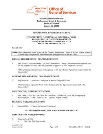
AUGER DRIVE DIAGRAMS AND PARTS LISTSDecalsThe above safety sign is located near the bottom of the hydraulic drive housing. If damaged or missing, order anew "DANGER" decal. We will gladly send a new one at no charge.Skid Pro Auger ManualRev. 7:17Page 9
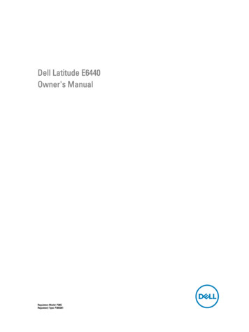
M Series Auger Drive - Set Up Assembly - Diagram AM Series Auger Drive - Set Up Assembly – Parts List AItem12345678910111213141516Skid Pro Auger ManualPart 8112310111732Description300 Hydraulic MotorO Ring (Not Shown)PlanetaryHousing½”-13X 1 ½” 12 PT Bolt½” Lock WasherAdapter 10MB X 8FPHose ½” X 96” W/ MP Both Ends9/16”-12 X 2” Bolt9/16” Lock WasherHousing Pin7/16” Lynch PinDecalWarning DecalSerial NumberM300 DecalRev. 7:17Qty.1111442266122211P a g e 10
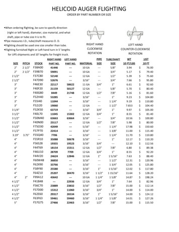
M Series Auger Drive - Planetary Gear Box - Diagram BM Series Auger Drive - Planetary Gear Box - Parts List BItem123456789101112131415161718192021Skid Pro Auger ManualPart 464112465112467112468HLWM8ZHCSM8DescriptionOutput ShaftOil SealBearing ConeBearing CupHousing7”-13x 1 7” Bolt7” Lock WasherBearing CupBearing ConeSpacer, Flat TonguedLock Nut Washer, M70Lock Nut, M70X2O RingRing Gear 77TSecondary Carrier Sub AssemblySun GearRetaining WasherCap, InputPipe Plug 3-8”-18 NPTLock Washer, M8Hex Head Bolt M X1.25 GRRev. 7:17Qty111116611112111111121212P a g e 11
NC Series Auger Drive - Set Up Assembly - Diagram ANC Series Auger Drive - Set Up Assembly – Parts List AItem1234567Part 50Z112610DescriptionHousing, NC DriveO-RING 3MM X 82MM BUNA 70BOLT 5/8"-11 X 2-1/4" GR5 PLLock Washer 5/8 ZPBOLT 1/2-13 X 1-1/2 GR5Z 12PTLock Washer 1/2 ZPMotor Hydraulic 300 White 111772111758112490-00111757111779Decal Serial NumberLynch Pin 7/16"Pinhousing M-Series - PlatedDecal NC-300Decal Danger-1Gearbox Planetary, M3Decal Skid Pro, SmallDecal, FEMA Small12111121Skid Pro Auger ManualRev. 7:17P a g e 12
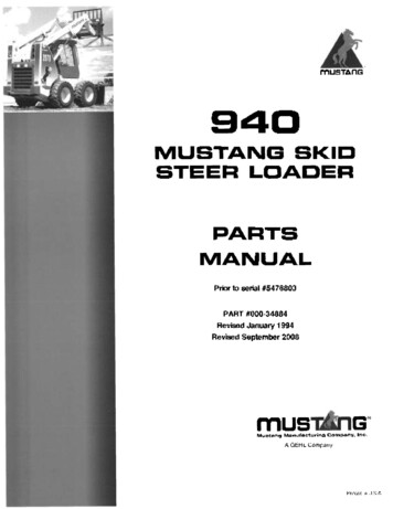
NC Series Auger Drive - Planetary Gear Box, 2” Hex - Diagram BNC Series Auger Drive - Planetary Gear Box, 2” Hex - Parts List BItem123456789101112131415161718Skid Pro Auger ManualPart 0-17112490-18DescriptionOutput ShaftOil SealBearing CupBearing ConeHousingPlug PipePlug MagneticWasher ThrustWasher LockNut BearingPin AlignmentGear RingSecondary Carrier Sub AssemblyGear SunWasher ThrustCoverWasher LockSocket Head BoltRev. 7:17Qty11221111112111111212P a g e 13
SKID PRO ATTACHMENT WARRANTYAttachments covered under this 48 Month Warranty includes:Planetary Auger DrivesSkid Pro warrants above attachments for forty-eight months from date of shipment, to the original owner.Warranty covers products to be free from defects in material and workmanship when properly set up andoperated in accordance with Skid Pro’s recommendations.WARRANTY CLAIM PROCEDUREAll warranty claims must be submitted within the manufacturer’s limited warranty period. Pictures and/ora video of the failing component(s) are required to properly document all potential warranty claims. Tosubmit a warranty claim, contact your Skid Pro Product Guru or complete a Warranty Claim Form on ourwebsite and send it along with supporting pictures/video to sales@skidpro.com. Upon receipt, thewarranty claim information will be reviewed and once determined to be a valid claim, a returnauthorization number will be issued for the return of the defective part(s) if applicable and replacementpart(s) will be shipped. If it is determined the defective parts are to be returned and they are not receivedby Skid Pro within 30 days of receiving the replacement parts, the Buyer will be charged for the cost ofthe replacement parts plus any shipping charges. Tampering with the failed part (i.e. disassembling amotor or cylinder) will void the warranty.EXCLUSIONS OF WARRANTYSkid Pro’s requirement for any issue with respect to attachments shall be limited to repairing or replacingthe defective part, as this is a parts-only warranty and does not include any labor to replace or install thepart or downtime from resulting issue. Skid Pro has full technical support & assistance to assure customerreplaces the part properly for optimal performance on attachment.This warranty shall not apply to any attachment’s wear items, or attachments that have been repaired oraltered outside the Skid Pro factory in any way, or that has been subject to misuse, negligence or accidentbeyond Skid Pro’s recommended use and/or machine rated capacity.This warranty is exclusive and in lieu of all other warranties and conditions. Skid Pro disclaims all otherwarranties and conditions, express or implied, including any implied warranties or conditions ofmerchantability or fitness for a particular purpose. In no event shall Skid Pro be liable for any special,incidental, indirect or consequential damage, whatsoever, including, but not limited to, loss or interruptionof business, lost profits, or loss of machine use, whether based on contract, warranty, tort, negligence,strict liability, statute or otherwise, even if Skid Pro has been advised of the possibility of such damages.No agent, employee, or representative of Skid Pro has any authority to bind said company to anyaffirmation, representation, or warranty concerning its machinery and/or attachments except asspecifically set forth herein. Any disagreement or dispute of warranty policy or customer expectations ofproduct, soundness, functionality, or performance would take place in Douglas County, Alexandria, MN,where Skid Pro operates.Skid Pro Auger ManualRev. 7:17P a g e 14
PO Box 982Alexandria, MN 56308Phone: 877-378-4642Fax: 320-759-1057www.skidpro.comsales@skidpro.comSkid Pro Auger ManualRev. 7:17P a g e 15
proper tools. 21) Before digging or otherwise operating the machine, you should carefully inspect the area to be worked, looking for and noting all gullies, or ditches, etc. and removing any posts,