Transcription
Registry of Motor VehiclesUMSProgrammer’s ManualRelease 6.0November 2002T21494-1002
Registry of Motor Vehicles – UMS Programmer’s ManualTable of ContentsCHAPTER 1. UMS OVERVIEW .1PROSCRIPTIONS.1RELATED MANUALS.1OVERVIEW .2CHAPTER 2. CONTROL-DISPATCH.9SYSTEM OVERVIEW.9General Overview .11Main Control.11Host Interface.12Output Services.12Mapping/Demapping Services.12Secondary Session Services.13Control/Dispatch Conventions .13General Structure .18Guest Side Conventions .19Host Side Conventions.20Inter-Process Communication.21Program Function-Key Standards .23Guest-Host Control Blocks .25Guest Common Area Structure.27UMS Software-Interface Hooks .30Host Common Area Structure.32CHAPTER 3. UMS Naming and Version Conventions.41CHAPTER 4. UMS LIBRARIES AND MODULE PROMOTION .43Proposed Module Movement Changes .44CHAPTER 5. UMS PROGRAM CONTROL TABLES .53Program Control Table Entry Guest (PCTEG) .53Source Code Example - PCTEG.54The PCTEG In Detail .56SYSPARM Options .58Assembled Code Example .61Hexidecimal Dump .68Program Control Table Entry Host (PCTEH) .71Source Code Example - PCTEH.75Assembled Code Example - PCTEH .77Hexidecimal Dump of PCTEH Example .84Internal Function Codes .87Internal Function Codes List.88CHAPTER 6. LXTABLE PROCESSING.91Feature Summary .91Detail Description .96The LXTABLE Macro .96The UMSLXTBL TYPE START.97Sample expansion, TYPE START .98The UMSLXTBL TYPE DETAIL .99Table of Contentsiii
Registry of Motor Vehicles – UMS Programmer’s ManualValue Checking .104Edit Checking .106Edit Type Table .107User Exit - LXTABLE .108User Exit Example .111Internal Field Values - UMSLXMAC .113Sample Map Source Fragment .114Sample Assembler Map Dsect .115LXTABLE Assembled Example .117Hexidecimal Dump of LXTABLE Example .137CHAPTER 7. SYSTEM UTILITY PROGRAMS .139Resident Utilities.139Date Conversion Routine.140Example of a COBOL Invocation .140Data-Name Address Routine .141Miscellaneous Edit Services .142In-Core Online Sort .143Non-Resident Utilities.144Violation Table Processing.144CHAPTER 8. CICS TABLES .149UMS Setup Options .149CHAPTER 9. UMS SCREEN MAPPING PROCEDURES .161CHAPTER 10. UMS ONLINE ERROR MESSAGES .171UGZ0004P - The Message Module .173Assembled Example of a Message Module .175Hexidecimal dump of Message Module Example .180CHAPTER 11. SPECIAL SYSTEM FUNCTIONS.181Limited Secondary Session.181UMS Screen Hop Facility .182ALARS-UMS Bridge.184GHOST Program - ESI/NDR/CDLIS .186CHAPTER 12. UMS BATCH.191Tape Processing .191CHAPTER 13. RECORD SURROGATES .195APPENDIX A: NON-UMS LXTABLE EDIT EXAMPLE.201APPENDIX B. GUEST PROCESS CONTROL TABLE.223APPENDIX C. HOST PROCESS CONTROL TABLE.237APPENDIX D. CICS MISCELLANEOUS .261CICS Abend Codes List.261CICS Queue Names .262APPENDIX E. UMS SYSTEM PROGRAMS.265GUEST-SIDE PROGRAMS.265HOST-SIDE PROGRAMS .266Table of Contentsiv
Registry of Motor Vehicles – UMS Programmer’s ManualAPPENDIX F. GUEST COMMON AREA .267COBOL Example.267ASSEMBLER Example.272APPENDIX G. FUNCTION DESCRIPTIONS .277Function Titles List .277APPENDIX H. CICS IDMS NETWORK RELATIONSHIPS.379NETWORK CONNECT OVERVIEW.379PRODUCTION ENVIRONMENT .379TEST ENVIRONMENT .380TRAINING ENVIRONMENT.382MRO ENVIRONMENT .383THE TMON V8.0 ENVIRONMENT.384CICS - IDMS REGION RELATIONS .385PRODUCTION ENVIRONMENT .385TEST AND TRAINING ENVIRONMENT.386Table of Contentsv
Registry of Motor Vehicles – UMS Programmer’s ManualTable of Contentsvi
Registry of Motor Vehicles – UMS Programmer’s Manual1UMS OverviewProscriptionsThis UMS PROGRAMMER’S MANUAL is provided to assist those users who have adefinite requirement to modify or extend the UMS application software. There are fiveimportant principles to guide such modifications and/or extensions:1.While the RMV provides problem determination and correction for the UMSGuest Software, it cannot provide such support to user-modified or extendedGuest Programs.2.The UMS System Control and Support Programs named UGZxxxxP may not bemodified. The only exception is for those modules involved in site definitionwhose modifications are specified in the Install Manual.3.All fields passed to the HOST for whatever purpose must successfully passtheir LXTABLE edit where such an edit is provided. The list on page 107 liststhe edits that must be employed. The section beginning on page 91 discusses theLXTABLE in detail. The Appendix beginning on page 203 provides discussionand examples of the LXTABLE use in programs outside of the UMS ControlStructure.4.Prior to making contact with the HOST, the UGTL transaction must haveexecuted successfully in the current execution of the CICS region concerned.5.Contact with the HOST will be effected only by means of the UMS SystemInterface programs supplied by the RMV. Please refer to #2 above.In addition, please read the convention section beginning on page 13 and the interfacesection beginning on page 21.Related ManualsUMS Installation Manual: This book discusses the installation of the stated release. Theseinstructions preview the UMS system from a “high level” viewpoint.Chapter One - UMS Overview1
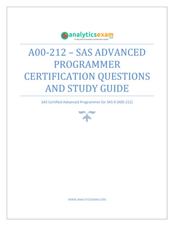
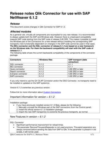
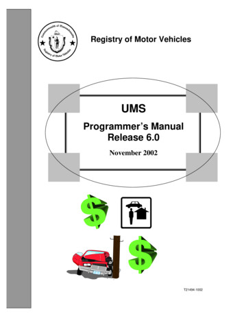
Registry of Motor Vehicles – UMS Programmer’s ManualUMS Technical Manual: This manual discusses in detail each of the UMS transactions,processing, programs, screens, records, and error messages. This is the best source,outside of the programs themselves, of understanding the operation of the UMSfunctions. Appendix G draws a synopsis for each function from this manual.UMS User Manual: This is a “How-To” for using the system. The audience for thismanual is the End User.UMS Customization Manual: This manual is a guide for modifying the UMS systemdistributed to the user community with the other manuals. It is a subset of this book.OverviewThe Uninsured Motorist System (UMS) was developed to allow insurance companies tonotify the RMV when a policy on a vehicle had been cancelled, creating a possibleuninsured motorist. The system operates in both the batch and on-line mode. Over time,enhancements have been made to the system to cover far more than insurance policychanges. It has intimate connections with ALARS (Automated Licensing and RenewalSystem) such that former distinctions are now blurred. To the same extent, theresponsibilities for these systems have changed as well.The UMS system is built on a client-server basis. The RMV computer is the server, orHost, for data on registrations, licensing, and related issues. Many of the clients or guestsare insurance companies or “outside” agencies with their own data processing facilitiesand needs. UMS provides them with a complete interface and set of applicationprograms to access the RMV data. They are free to make modifications to the UMSGuest programs. They are, however, required to use the UMS Structural and LXTABLEedit facilities so they can maintain a maximum posture of release independence andconform to data edit requirements. The system design places much of the workload ontheir machine. The UMS design makes simple requests of the Host database system sothat the database run-units are short with as few I/Os as possible to give the very bestavailable response for all users.A client who either modifies the released software or creates its own assumes fullresponsibility for conforming to RMV data Standards.A dozen CICS and IDMS regions provide the various classes of service required. Thediagram on page 5 illustrates the relationships. In all cases, CICS is the teleprocessingand application front-end for the IDMS CVs. The database services are filtered throughthe Logical Record Facility (LRF) of IDMS. The General User CICS region is the LU6.2contact point in the Host for “guest” users who have connect privileges during normalbusiness hours.Chapter One - UMS Overview2
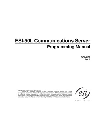
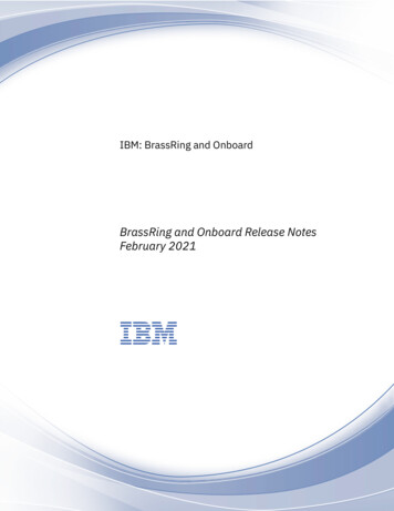
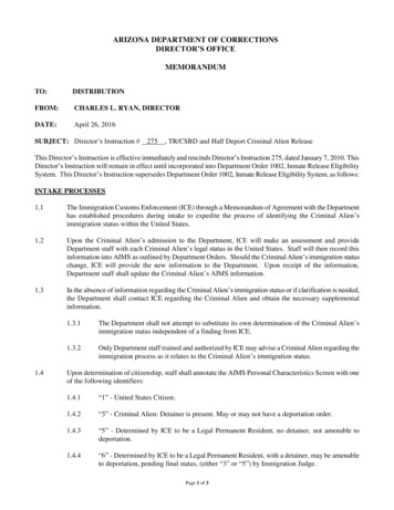
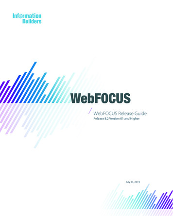
Registry of Motor Vehicles – UMS Programmer’s ManualThree general types of Guest-Host interface are in service. These services are illustratedin the following pages. In Type 1, the UMS Guest software resides in the Guest’smainframe and uses LU6.2 services to reach the RMV computer (see page 6). The RMVhost software does some validations, security checking, and the IDMS database I/O. TheType 2 interface is used by several official agencies (see page 7). In this, the Guestsoftware runs in the RMV CPU and the LU6.2 facility is replaced by an interfaceprogram. The Type 3 interface is similar to Type 1 but either the machine is not an IBMor the user (guest) has heavily modified the “guest” software (see page 8). This is a caseof a “black box” communicating via LU6.2. We have no particular responsibility forproblems with this type of “guest” software.For a more detailed description of functions or for error message information, consultthe UMS Technical Manual for this release level.The overall design objectives are to use single function, independent modules andsegregate the front-end (CICS or TP) and back-end (IDMS or database) processing. Thishas been achieved through several subordinate objectives or techniques. The first UMSdesign objective is to place as much of the application work as possible in the Guestsoftware. The second objective is to drive the Guest and Host software systems with anapplication control structure. This structure, called Control/Dispatch (CD), supports thethird objective, which is that development and maintenance time for applications beminimized. CICS provides all the needed control facilities, but they must be hard-codedinto the programs. The programs become larger in size and complexity, and changes tothe processing structure cause changes to a number of modules. It is also difficult to runnew and old versions of programs in parallel.The UMS CD system is table driven so that control flow changes are only applied in onetable. Common services, such as screen mapping, data movement, field editing, and errormessage handling are all directed by the CD system and occur in system modules outsideof the application program. The chapters on Control Dispatch, UMS Program ControlTables, and LXTABLE Processing describe these control mechanisms in detail. Manyutility routines are provided so that the application program can concentrate on thespecific business function and just call for basic “services” such as date routines.Components are intentionally isolated so that debugging and error resolution is simplifiedand new functions can be added without changing or disturbing the existing ones.The fourth objective is function-reuse. This applies particularly to the Host sidefunctions that provide the database services. If a new requirement needs half of the dataprovided by Host-function “X” and additional data not provided anywhere else, a newHost function will be written to get the “additional data.” In this way, if there is aproblem with the function “X” data, there is still only one place to look for the problem.There would be many possibilities if each new data requirement was met with a newfunction providing only a specific group of fields. Such a proliferation would beexpensive in terms of development and a nearly insupportable nightmare in terms ofmaintenance and problem resolution.Chapter One - UMS Overview3
Registry of Motor Vehicles – UMS Programmer’s ManualThe fifth objective is to make the interface to the DBMS as narrow and well defined aspossible. This ensures that the impact of changing the DBMS would be minimal to theapplication systems. As a corollary, all programs must use the application “common typeservices,” which operate through specific interfaces. This aids in development and, incase of error or needed change, there is only one place to apply the correction and then allprograms will be using the new code. This principle is extended further in cases such aslicense plate number edits where the edit rules set is elaborate and subject to suddenchange. The edit code is in a separate routine accessible to all applications but it is drivenby a set of rules that is downloaded from the Host at Guest start-up time. In this way, therules could be changed daily with no visibility to the users at all. This design eliminatesthe need to manually distribute zaps or complete new copies of the rules tables andensures that all users are totally and painlessly up to date.Chapter One - UMS Overview4
Registry of Motor Vehicles – UMS Programmer’s ManualOLSJCIQN(Imaging)Chapter One - UMS Overview5
Registry of Motor Vehicles – UMS Programmer’s ManualChapter One - UMS Overview6
Registry of Motor Vehicles – UMS Programmer’s ManualChapter One - UMS Overview7
Registry of Motor Vehicles – UMS Programmer’s ManualChapter One - UMS Overview8
Registry of Motor Vehicles – UMS Programmer’s Manual2Control - DispatchSystem OverviewThe UMS Guest System requires initialization once the CICS region's startup iscomplete. The UGTL transaction invokes UGZ0015P to perform the various operations.This process is discussed in more detail in a subsequent chapter. If this process is notcompleted, UMS will abend with a code of “UGTL” or “UGTH.”The transaction “UG03” is the normal entry to the UMS Guest Processing. It invokesUGZ0001P, the Guest Side Control Program. This routine controls the processing threadfor the transaction. Application programs that are invoked usually return to this routineunless they abend. The control program examines the control structures and passes thethread to the next program or function for the task. The focus of control is the systemportion of the common area and the PCTEG entry in UGZ0002P for the transaction inflight. The PCTEG is discussed in detail later. It contains a list of programs to beinvoked in turn to do the work of the transaction. If the automatic screen mapping,demapping, and editing feature is to be used, the name of the (LX) control table is given.If a special clean-up program is needed, its name is given. Flags show the ability to doupdates, scrolling, and re-scrolling as well as the ability to communicate with the HostSystem. Some additional features are discussed in the detailed treatment. The systemmay also be invoked by external programs that start the transaction UG05 (that points toUGZ0008P). UGZ0008P can be called directly by link or xctl.At transaction initialization time, the data from the corresponding PCTEG entry is placedinto the system portion of the Guest Common Area. The structure of the Guest (andHost) Common Areas are briefly covered in the following section of this chapter. Thecontrol program and the application both refer to the Guest Common as the transactionprogresses. The application moves data elements only so a change of a program name istransparent and will only require one change in the PCTEG entry for that transaction.The order of the program names in the PCTEG is function dependent and the applicationcan vary the name moved to the 'next program' field depending on run-time conditions.The first named program in the PCTEG list is the first one called by the control programonce mapping is complete. Any program can only be first for one transaction (and its testversion, 1st character 'T'). When a screen of data is to be processed, the designated LXmap table is loaded and the LX map program completes its work before that firstapplication program is invoked. If the map module detects errors it can cycle througherror-message issue and re-try the mapping until the input is error free. The data from thescreen is placed into the dsect in the common area before the application gains control.Chapter Two - Control - Dispatch9
Registry of Motor Vehicles – UMS Programmer’s ManualThe program can edit the data further and issue error messages of its own to the screenwhich will continue this cycle to correctness.A number of service routines are available to do common functions such as upper-caseconversion and date conversions. These are described in Appendix G - FunctionDescriptions. Calls to the Host side for database services can be made for retrieval and/orupdate. Control can be returned to the caller or another program it designates. Each timethe thread returns control to CICS (except for logoff), the control program sets the nexttransid to UG04. This id shows a continuing transaction to insure initialization that doesnot negate work already done. If access to the Host System is indicated a Host InterfaceArea block of storage is acquired and initialized by the Control Program. When the workis complete and data is written to the screen, the Control Program invokes the LX-Tablefeature to move the data to the screen. As is described in the LX-Table processingchapter, exit routines may be summoned during screen processing (in or out) to performspecial editing. These routines can generate error messages.Error messages are designated by a numeric value in Common Storage. This value isused in conjunction with UGZ0004P, the Error Message Dictionary, to retrieve the actualtext and place it in the output map. When the thread comes back to the Control Programas completed, the designated clean-up program , normally UGZ0005P, issues the write tothe terminal and makes any required final “adjustments.”Each UMS screen normally has an LX table, guest input program, one or more hostprograms, and a guest output program. When the user enters data onto the screen, the LXtable processor uses the LX table for that screen and edits the data. Next, the guest inputprogram receives control to format the guest-to-host blocks (refer to the Guest-to-HostBlocks section) and performs any additional editing. The guest input program passescontrol to the host side by using an internal function code to indicate which hostprograms to invoke (refer to the Internal Function Codes section). The host programsperform database access and formats the needed data into the host-to-guest blocks. Theguest output program receives the host-to-guest blocks, uses this data to make decisionsabout screen highlighting, and performs other miscellaneous tasks. The last programs toreceive control are the LX table processor and the Clean up Program, UGZ0005P. Theseprograms use the screen's LX table to map the data from the General Storage Area (GSA)to the screens, and sends the screen back to the user.Chapter Two - Control - Dispatch10
Registry of Motor Vehicles – UMS Programmer’s ManualGeneral Overview of UMS-Guest Control/ DispatchControl/Dispatch (often abbreviated CD) is the name given to the various service levelfunctions provided for the UMS guest application programs. There are two purposes toCD. The first is to provide a level of standardization to functions common to multipleapplication areas. The second is to perform functions deemed overly complex for thetypical application module.General areas of functionality:A.B.C.D.E.Screen/CRT/CICS - Map managementMemory managementFunction validationHost interfaceTable servicesEach of these areas is a component of CD, and may exist as a unique module, or as acomponent of a multi-purpose module(s).Main ControlAll UMS transactions are “wired” to the same PCT entry. UMS requires at least 2transactions to run. One (typically UG03) is referred to as the initialization transaction.Another (typically UG04) is referred to as the default run transaction. When the maincontrol program gets control, it determines if this is an initialization call by checking thetransaction name against the initialization transaction name. If the initializationtransaction is found, the common area is cleared, a flag indicating initialization is set, thecurrent map-name is set to the logon map, and control is transferred to output services.Note that when the user comes back through, the logon process is treated in a manneressentially the same as any other function, except that the user is required to completelogon before a function change is allowed.UMS supports three mechanisms of saving COMMAREA (Application-high core,VSAM and CICS-high core). The main control module insures that the currentCOMMAREA image is in an area located below the line.CD determines if the user has changed the function-code. If so, the new function code isvalidated. If it is valid and all required modules are present, the internal data is changedto cause the selected function to be dispatched. If an error is detected, output services areinvoked to send the message to the user.If no function is currently selected, output services are invoked to inform the user.Chapter Two - Control - Dispatch11
Registry of Motor Vehicles – UMS Programmer’s ManualIf a function key has been pressed, the meaning of the key is checked for validity in thecurrent environment. If it is invalid, output services are invoked to send the errormessage to the user. Otherwise, the appropriate service is invoked.The only remaining action is to dispatch the application. Most applications use tabledriven mapping/ demapping (LXTBL) services, and a few do not. Those that do not useLXTBL services are transferred directly. Those that use LXTBL, require that services bedispatched before the application.Host InterfaceWhen an application determines that it must obtain data from the host, it builds theapplication portion of a host parameter block and then transfers to the host interfacemodule defined for the guest. The interface module checks for the host being active,completes the control portion of the host parameter block and transmits the data to thehost. When the response is received, the host interface module transfers back
The Uninsured Motorist System (UMS) was developed to allow insurance companies to notify the RMV when a policy on a vehicle had been cancelled, creating a possible uninsured motorist. The system operates in both the batch and on-line mode. Over time, enhancements have been made to the system