Transcription
NEW MEXICOWATER SYSTEMS OPERATORCERTIFICATION STUDY MANUALVersion IV, January 2011New Mexico Environment DepartmentUtility Operator Certification ProgramNMED Surface Water Quality BureauPO Box 5469Santa Fe, NM 87502
On the cover:San Juan-Chama Drinking Water Project
NEW MEXICOWATER SYSTEMS OPERATORCERTIFICATION STUDY MANUALVersion IVJanuary2011New Mexico Environment DepartmentUtility Operator Certification ProgramNMED Surface Water Quality BureauPO Box 5469Santa Fe, NM 87502
INTRODUCTIONThe “N EW M EXCIO W ATER S YSTEMS O PERATOR to the chapter topics. There is only one correct answer forCERTIFICATION STUDY GUIDE” was developed by Fred the Sample Test Questions. No answer sheet is provided.Ragsdale of Ragsdale and Associates under contract with You will have to look them up.NMED Surface Water Quality Bureau. With this edition thetitle has changed to The “NEW MEXCIO WATER SYSTEMS Distribution Systems exams will include informationOPERATOR CERTIFICATION STUDY MANUAL” to reflect thefrom Chapters 1-5, 7-10, and 13-14.addition of further study material. It should be used as a tool Small Water Systems exam will include informationto assist Water Systems operators in New Mexico infrom Chapters 1-5, 7-11, and 13.preparation for taking the New Mexico Distribution Systems Advanced Small Water Systems exam will alsoOperator, Small Water Systems Operator, and Water Systemsinclude information from Chapters 6 and 12.Operator certification exams. In New Mexico Water Water Systems Class 1 exam will includeCertification is divided into the following areas:information from Chapters 1-4, 7-11, and 13-14. Water System Class 2 exam will include§ Four classes of Water System Operatorinformation from Chapters 1-11 and 13-14.certification Water Systems Class 3 and 4 exams will include§ Three classes of Distribution Systems Operatorinformation from chapters one through fourteen.certification§ Two classes of Small Water Systems Operator The certification exams use several texts as referencecertificationmanuals for exam topics. Each chapter of the study manualcontains references to specific chapters of these manualsThis manual is not intended to be a complete reference manual for for those who wish to access more information on the topicstechnical information. Its purpose is to guide the reader to study covered in that particular section.material for each of the major subject areas for each of the erseverypossible¾ Office of Water Programs, California Statepoint on which an operator may be tested. However, it is intendedUniversity, Sacramento, Water Treatment Plantto be comprehensive in its coverage of the essential informationOperation. 4th ed., 1999, Volumes 1 & 2.for each exam. As new technologies are developed and become¾ Office of Water Programs, California Stateavailable in the State of New Mexico further additions will beUniversity, Sacramento, Small Water Systemsmade to the Study Manual to assist operators in understandingO&M. 4th ed., 2001.those advanced water treatment technologies.¾ Office of Water Programs, California StateUniversity, Sacramento, Water DistributionThe manual is divided into fourteen basic chapters. In theSystem O&M. 4th ed., 2000.future a chapter fifteen will be added containing information¾ ACR Publications, Inc., Skeet Arasmith,on emerging advanced water treatment technologies. TheIntroduction to Small Water Systems, 1993.manaul also contains a useful Appendix: EPA manual¾ Fletcher Driscoll/US Filter, Groundwater and“Response Protocol Toolbox: Planning for and RespondingWells, 2nd Edition, 1986.to Drinking Water Contamination Threats and Incidents”.Each chapter in the study manual has basic and advancedstudy questions and sample test questions that are intended Special thanks to:help the individual determine the type of information that is NMED SWQB Utility Operator Certification Programcovered in an exam. Basic questions will generally cover for funding; Bob Padilla for his graphics; the New Mexicoinformation in the Small Water Systems exams and the Class Utility Operator Certification Advisory Board for chapter1 and 2 for Water Systems and Distribution Systems exams. reviews; everyone who helped to proof read the first draftAdvanced questions will cover information in the Water for typos; Bill Peifer for help formatting the original text;Systems Class 3 and 4 and Distribution Systems Class 3 Marilyn Still for further typo revisions; and Robert &exams. The study questions and sample test questions are Nancy Gott of Gott Consulting Services for structuringdesigned to direct the reader to exam information that is related supplemental text and reformatting the study guide.i
NEW MEXICO ENVIRONMENT DEPARTMENTSURFACE WATER QUALITY BUREAUUTILITY OPERATOR CERTIFICATION PROGRAMThe New Mexico Water Quality Control Commission,through the New Mexico Environment Department(NMED), grants certification for competency to theoperators of water and wastewater systems. The UtilityOperator Certification Program (UOCP) conducts thetesting for certification. Certain requirements must be metbefore an operator is eligible to take a certificationexamination.An operator begins the process by completing a testapplication from the Utility Operator Certification Program.Applications will only be accepted if they are submitted atleast 30 days prior to the exam date. A certification officerwill review each application to determine if the operator iseligible to take the requested examination. An applicationmust be submitted every time a test is taken. Examinationsare given several times a year at various locations aroundthe state. Fees range from 25.00 - 30.00 dependingon the examination. A check or money order for the properamount must accompany each exam application and paidto Utility Operator Certification Program.Certificates must be renewed every three years. The All correspondence, including applications, should berenewal date will be the last day of the certificate holder’s mailed to:NMED Surface Water Quality Bureaubirthmonth following the third anniversary of the certificate.Utility Operator Certification ProgramThe UOCP also handles renewal of certificates. RenewalPO Box 5469fees ranges from 20.00 - 30.00 depending on the levelSanta Fe, NM 87502of certification to be renewed per certificate.Please feel free to call the Utility Operator CertificationProgram to request information on exam application forms,exam dates and locations, or certification and renewal.The telephone number for the office is 505-827-2804.The Utility Operator Certification Program maintainstraining credits for certified operators only. Each operatormust keep a record of all training credits earned. Anyonewho intends to apply for NM certification must includedocumentation of training credits when the application issubmitted. Certified operators that are taking higher levelexams may also have to submit training creditdocumentation to update training record files at the UtilityOperator Certification Program.i
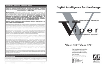
IMPORTANT FACTS ABOUT OPERATOR CERTIFICATIONAn operator, as defined by NM Water Quality Control CommissionRegulations, is “any person employed by the owner as the personresponsible for the operation of all or any portion of a water supplysystem or wastewater facility. Not included in this definition aresuch persons as directors of public works, city engineers, citymanagers, or other officials or persons whose duties do not includeactual operation or direct supervision of water supply systems orwastewater facilities.”The Utility Operator Certification Advisory Board (UOCAB) is aseven-member board appointed to function with the WQCC toestablish qualifications of operators, classify systems, adoptregulations, and advise the administration of the Utility OperatorsCertification Act. Its members are drawn from certified watersystems operators and wastewater facility operators in thethroughout the State of New Mexico.Experience that includes operation, maintenance, or repair of watertreatment and water distribution systems is accepted based onwhether it is full or part-time. The NM Utility Operator CertificationAdvisory Board will review and approve experience in other relatedfields, such as commercial plumbing or utility construction. Creditfor part-time experience will be based on the percentage of timedevoted to actual operation or maintenance. Full time water orwastewater laboratory experience may be counted as operatorexperience at a rate of 25% of actual experience. The credit forthis experience will be determined by review of the UOCAB.Under the Utility Operator Certification Act, “a certified operator isa person who is certified by the commission as being qualified tosupervise or operate one of the classifications of water supplysystems or wastewater facilities”. Experience is “actual workexperience, full or part-time, in the fields of public water supply orpublic wastewater treatment. Work experience in a related fieldmay be accepted at the discretion of the commission”. Any claimof related experience will be reviewed by the Water Quality controlCommission (WQCC) or its advisory body, the Utility OperatorsCertification Advisory Board.BASIC CERTIFICATION REQUIREMENTSThere are three basic requirements an operator mustmeet to qualify for New Mexico certification. Allcertified operators must have at least one year ofactual experience in operation or maintenance of apublic water system. All levels of certificationrequire high school graduation or GED (seesubstitutions). All levels of certification require acertain number of training credits in water systemsO&M or related fields.EXPERIENCEClass 1Small SystemsClass 2Class 3Class 4TRAININGCREDITS1 year*101 year*102 years*304 years*501 year as Class 3 80EDUCATIONHS Grad or GED*HS Grad or GED*HS Grad or GED*HS Grad or GED*HS Grad or GED*See SubsitutionsSUBSTITUTIONS An Associate degree in a two-year program at an approvedschool in the water and/or wastewater field, and six months ofactual experience in that field (which may be accrued before,during, or after the school program) may be substituted for therequirements of any level up to and including Class 2. An Associate degree in a two-year program at an approvedschool in the water and/or wastewater field and twelve monthsof actual experience in that field (which may be accrued before,during, or after the school program) may be substituted for therequirements of any level up to and including Class 3. Completion of at least three years of actual experience in thewater and/or wastewater field, plus high school graduation orequivalent, plus 15 semester hours of successfully completedcollege education directly related to the water or wastewaterfield may be substituted for any level up to and including Class 3. A Bachelor Degree in a major directly related to the water orwastewater field, plus two years of actual experience in thatfield may be substituted for any level up to and including Class 3.One year of additional experience may be substituted for the highschool graduation or GED requirement for all classes except Class4. Education may be substituted for experience or training creditsin some cases. The education must be in a water or wastewaterrelated field. One year of vocational education can be substitutedfor up to one year of experience. Associate and Bachelor degreesin a related field may be substituted for up to three years ofexperience and 50 training credit hours, depending on the amountof actual experience. The criteria for substitution of education forexperience are as follows: No more than one year (30 semester hours) of successfullycompleted college education in a non-related field may besubstituted for an additional six months of the requiredexperience. One year of approved vocational school in the water and/orwastewater field may be substituted for only one additionalyear of the required experience.iii
TABLE OF CONTENTSCHAPTER 1: WATER SYSTEMS OVERVIEWMEETING WATER SYSTEM DEMANDSSOURCES OF SUPPLYMEETING WATER QUALITY STANDARDSMEETING WATER CONSUPTION & PEAK DEMANDSCOMPONENTS OF A WATER SYSTEMSERVICESOPERATOR RESPONSIBILITIESSTUDY & SAMPLE TEST QUESTIONSSAMPLING SCHEULES & TECHNIQUESREPORTING & SHIPPING CONSIDERATIONS1-11-11-11-21-21-21-31-3TABLE 2.1 PRIMARY CONTAMINANTSTABLE 2.2 INORGANIC CONTAMINANTSTABLE 2.3 PRIMARY CONTAMINANTSORGANIC CONTAMINANTSTABLE 2.4 RADIOACTIVE CONTAMINANTSRADIOACTIVE CONTAMINANTSBACTERIOLOGICAL CONTAMINANTSSECONDARY CONTAMINANTSMONITORING & REPORTINGBACTERIOLOGICAL VIOLATIONSACTION PLAN FOR VIOLATIONSOTHER NEW REGULATIONSSTUDY & SAMPLE TEST QUESTIONSFIGURE 3.1 THE WORLD’S WATERFIGURE 3.2 WATER MOLECULE4-2RETAKES & VIOLATIONSSTUDY & SAMPLE TEST QUESTIONS4-24-3TYPES OF DISINFECTIONCHLORINE TREATMENT TERMSDISINFECTION REQUIREMENTSBREAKPOINT CHLORINATION2-12-12-22-22-25-2TESTING FOR CHLORINE RESIDULASGENERAL CHLORINE SAFETY5-35-3CHLORINATION EQUIPMENT2-2FIGURE 5.3 GAS CHLORINE INSTALLATIONFIGURE 5.4 CROSS SECITON OF A 1-TON CYLINDERFIGURE 5.5 150 LB CHLORINE GAS FEED UNITTABLE 5.2 TROUBLESOOTING GAS CHLORINATORSFIGURE 5.6 TYPICAL HYPOCHLORINATION SYSTEM2-22-22-22-32-3EMERGENCY RESPONSE PROCEDURESULTRAVIOLET LIGHT2-32-32-42-4TABLE 5.3 EMERGENCY RESPONSE PLANFIGURE 5.7 UV DISINFECTION SYSTEMSTUDY & SAMPLE TEST QUESTIONSFLUORIDE FEED SYSTEMSFIGURE 6.1FLUORIDE FEED SYSTEMS3-23-3SODIUM FLUORIDE SATURATORSFIGURE 3.3 THE HYDROLOGIC CYCLE3-3MONITORING FLUORIDE CONCENTRATIONSSTUDY & SAMPLE TEST QUESTIONSFIGURE 3.4 FRESH WATERFIGURE 3.5 UNUSABLE FRESH WATERTABLE 3.1 LOCATION OF THE WORLD’S WATERFIGURE 3.6 WATER DISTRIBUTION BY SYSTEMFIGURE 3.7 WATER DISTRIBUTION BY POPULATIONSTUDY & SAMPLE TEST QUESTIONSFIGURE 6.2 SODIUM FLUORIDE SATURATOR3-53-53-53-53-63-6FIGURE 4.1 WATERBORNE DISEASESCOLIFORM GROUP OF 6-26-26-3CHAPTER 7: DISTRIBUTIONPIPED SYSTEMMAIN LINE PIPING MATERIALSFIGURE 7.1 DIP ON TRUCKTABLE 7.1 PIPE TYPESFIGURE 7.2 RUBBER RING PUSH-ON JOINTFIGURE 7.3MECHANICAL JOINTFIGURE 7.4 ASBESOS CEMENT (A.C.) PIPEFIGURE 7.5 AC COUPLINGFIGURE 7.6 DRESSER TYPE COUPLINGFIGURE 7.7 STEEP PIPE, DIPPED AND WRAPPEDFIGURE 7.8 PVC - INTEGRAL BELL & SPIGOT3-6CHAPTER 4: WATER SAMPLINGNEW MEXICO CONSERVATION FEEWATERBORNE PATHOGENTS5-35-4CHAPTER 6: FLUORIDATION3-13-13-1DISTRIBUTION OF WATER ON EARTHHYDROLOGIC CYCLEDISTRIBUTION OF WATER5-15-15-25-2FIGURE 5.1 BREAKPOINT CURVETABLE 5.1 CHLORINE SYMPTOMSFIGURE 5.2 CHLORINE CYLINDER VALVECHAPTER 3: INTRODUCTION TO DRINKING WATERWHAT IS WATER?TABLE 4.1 BAC-T SAMPLE FORMCHAPTER 5: DISINFECTIONCHAPTER 2: SAFE DRINKING WATER ACTPUBILC WATER SYSTEMSPRIMARY 7-27-27-37-37-3
FIGURE 7.9 PVC INTEGRAL BELL CROSS-SECTION 7-4FIGURE 7.10 CROSS-SECTION OF PRETENSIONEDCONCRETE CYLINDER PIPE JOINT7-4FIGURE 7.11 HDPE HEAT FUSED WELDED JOINT 7-5BEDDING & BACKFILLING THE PIPEFIGURE 7.12 PIPE BEDDINGFIGURE 7.13 BACKFILLING THE PIPEPIPE PRESSURE RATINGSSEPARTION OF WATER 7 SEWER LINESCLEANING WATER LINES7-77-77-77-67-77-87-9FIGURE 7.18 FIRE HYDRANTSSERVICE LINESFIGURE 7.19 SERVICE LINE INSTALLATIONWATER METERSFIGURE 7.20 TYPES OF METERSREADING METERSFIGURE 7.21 WATER METER DIALTABLE 7.3 LOST WATERDISTRIBUTION SYSTEM HYDRAULICSFIGURE 7.22 THRUST RESTRAINTSTABLE 7.4 FRICTION LOSSCORROSION CONTROL7-97-97-97-10FIGURE 9.13 MECHANICAL SEAL COMPONENTSFIGURE 9.14 HOW TO DETERMINE TOTAL HEADFIGURE 9.15 PUMP CURVEFIGURE 9.16 HOW TO DETERMINESHUT-OFFHEAD7-117-127-127-12COMMON OPPERATIONAL PROBLEMS7-137-13TABLE 9.2 CAUSES OF CAVITATION7-137-13ELECTRIC MOTORSSTUDY & SAMPLE TEST QUESTIONSPUMP MAINTENANCEPUMP PACKING7-157-16TABLE 10.1 DAMAGES CAUSED BYPACKING FAILURE7-167-177-177-187-18BEARING MAINTENANCEFIGURE 10.1 REPACKING A PUMPCOUPLINGSFIGURE 10.2 GEAR COUPLINGFIGURE 10.3 FLEXIBLE GRID COUPLING7-19ALIGNMENTFIGURE 10.4 TYPES OF MISALIGNMENTCHAPTER 8: WATER STORAGEFIGURE 8.1 SACRIFICIAL ANODES USED FORCATHODIC PROTECTIONHYDROPNEUMATIC STORAGEFIGURE 8.2 TYPES OF PNEUMATIC TANKSFIGURE 8.3 DRAWDOWNSTUDY & SAMPLE TEST 79-79-79-89-99-99-99-109-11CHAPTER 10: MECHANICAL SYSTEMS7-147-14CROSS CONNECTION CONTROLWATER STORAGEGROUND STORAGE TANKS9-17-147-15STUDY & SAMPLE TEST QUESTIONSPUMP HYDRAULICS7-11FIGURE 7.23 BAYLIS CURVEFIGURE 7.24 BACKPRESSUE WITH BOILERSFIGURE 7.25 AIR GAPFIGURE 7.26 ATMOPHERIC VACUUM BREAKERFIGURE 7.27 DOUBLE CHECK VALVEFIGURE 7.28 RPZ DEVICEFIGURE 9.1 IMPELLER ROTATION &CENTRIFUGAL FORCETABLE 9.1 PUMP CHARACTERISTICS OVERVIEWFIGURE 9.2 HORIZONTAL SPLIT CASECENRIFUGAL PUMPFIGURE 9.3 END-SUCTION CENRIFUGAL PUMPFIGURE 9.4 VERTICAL TURBINECENRIFUGAL PUMPFIGURE 9.5 SHAFT SLEEVEFIGURE 9.6 PUMP BEARINGSFIGURE 9.7 THE VOLUTEFIGURE 9.8 SUCTION PIPINGFIGURE 9.9 LEAK BACKFIGURE 9.10 STUFFING MATERIALFIGURE 9.11 SEAL WATERFIGURE 9.12 STUFFING BOX CROSS-SECTION7-67-6FIGURE 7.14 LAUNCHING A PIGFIRE HYDRANTSCENTRIFUGAL PUMPS7-6WATER LINE REPAIRSDISINFECTION OF WATER LINESDISTRIBUTION SYSTEM VALVESTABLE 7.2 VALVE MAINTENANCEFIGURE 7.15 NON-RISING STEM GATE VALVEFIGURE 7.16 BUTTERFLY VALVEFIGURE 7.17 ALTITUDE VALVESCHAPTER 9: PUMPS & MOTORSINSTRUMENTATIONCHEMICAL FEED SYSTEMS8-18-1FIGURE 10.5 GRAVIMETRIC CHEMICAL FEEDERFIGURE 10.6 FEEDBACK CONTROL LOOPFIGURE 10.7 VOLUMETRIC CHEMICAL FEEDERFIGURE 10.8 PERISTALTIC PUMPFIGURE 10.9 DIAPHRAGM PUMP8-28-28-38-33STUDY & SAMPLE TEST 0-410-410-510-510-510-610-610-610-7
CHAPTER 11: GROUNDWATER & WELLSHYDROLOGIC CYCLEFIGURE 11.1 GROUNDWATER &THE HYDROLOGIC CYCLEWATER WELL LOCATIONWATER WELL CONSTRUCTIONFIGURE 11.2 ARTESIAN & WATER TABLEAQUIFERSSANITARY PROTECTION OF THE WELLFIGURE 11.3 GROUTING A WELL CASINGDEVELOPING A WELLGRAVEL PACKED WELLSFIGURE 11.4 GRAVEL PACK WELLCONSTRUCTIONFIGURE 11.5 GRAVEL PACK WELL TYPESDISINFECTING WATER WELLSWELL PUMPSFIGURE 11.6 VERTICLE TURBINECENTRIFUGAL PUMPFIGURE 11.7 SHAFT LUBRICATION SYSTEMSWELL SCREENSFIGURE 11.8 WELL SCREENSWELL HYDRAULICSCHAPTER 12: SURFACE WATER11-1SURFACE WATER SOURCESINTAKE STRUCTURES11-1FIGURE 12.1 LAKE INTAKE STRUCTURE11-211-2SURFACE WATER QUALITYSOLUBILITY OF SALTSTABLE 12.1 CHEMICAL NAMES & SYMBOLSTABLE 12.2 WATER TREATMENT CHEMICALS11-311-4PH11-4PHYSICAL / CHEMICAL TREATMENTREMOVAL OF COLORREMOVAL OF BACTERIAREMOVAL OF TASTE AND ODORS11-511-5TABLE 12.3 HARDNESS COMPOUNDS11-611-6IN-PLANT TREATMENTREMOVAL OF MINERALS11-711-811-911-9FIGURE 11.9 WATER WELL HYDRAULIC TERMS 11-10MEASURING STATIC & PUMPING LEVELS11-10FIGURE 11.10 MEASURING STATIC &PUMPING LEVELS11-11THE WELL LOGTABLE 11.1 WELL LOG DATATROUBLESHOOTING WELL PROBLEMSFIGURE 11.11 WATER PROBLEM CLOGGED SCREENFIGURE 11.12 WATER PROBLEM SAND BRIDGINGCLEANING INCRUSTED WELL SCREENSPUMP RELATED PROBLEMSFIGURE 11.13 WATER PROBLEM MECHANICAL PUMPTABLE 11.2 FORCES THAT CAUSESHAFT STRETCHTABLE 11.3 WELL TROUBLESHOOTINGFLOW CHARTTABLE 11.4 TROUBLESHOOTING WELL PUMPSSTUDY & SAMPLE TEST QUESTIONS11-11FIGURE 12.9 STATIC IN-LINE MIXERCOAGULATION PRETREATMENT EQUIPMENT11-1212-4OTHER MINERAL PROBLEMSCONTROL OF TURBIDITY AND COLORFIGURE 12.6 ALUM IN WATERFIGURE 12.7 POLYELECTROLYTEFIGURE 12.8 JAR TEST APPARATUS11-1112-312-312-712-8COAGULATION - THEORY11-1112-212-3SOFTENING CHEMICAL REACTIONSOTHER SOFTENING PROCEDURESFIGURE 12.3 CONVENTIONAL WATERTREATMENT PLANT DIAGRAMTABLE 12.4 SETTLING RATESFIGURE 12.4 HYDROPHOBIC PARTICLESFIGURE 12.5 HYDROPHILLIC PARTICLES11-912-212-4FIGURE 12.2 PH 112-1212-1212-1312-1312-13FIGURE 12.10 DUAL COMPARTMENT RAPIC MIX 12-1311-1211-13FLOCCULATION EQUIPMENTFIGURE 12.11 TYPES OF FLOCCULATORSSEDIMENTATION EQUIPMENT11-1312-1312-1412-14FIGURE 12.12 FOUR ZONES OFA SEDIMENATION BASIN12-15FIGURE 12.13 RECTANGULARSEDIMENATION BASIN12-15FIGURE 12.14 CIRCULAR SEDIMENATION BASIN 12-1511-1311-1411-15UP-FLOW CLARIFIERS11-16FIGURE 12.15 UP-FLOW CLARIFIERFILTRATION EQUIPMENTFIGURE 12.16 PRESSURE FILTERFIGURE 12.17 SLOW SAND FILTERFIGURE 12.18 FILTER UNDERDRAIN SYSTEMFIGURE 12.19 WHEELER FILTER BLOCKFIGURE 12.20 LOSS OF HEAD GAUGEFIGURE 12.21 TYPICAL FILTER 2-1812-19
FILTER OPERATIONFILTER BACKWASH PROCEDURES12-1912-19FIGURE 12.22 FILTER BACKWASHVALVE POSITIONS12-20TROUBLESHOOTING FILTER PROBLEMSCLEANING FILTER BEDSHIGH RATE FILTERS12-2012-2112-21FIGURE 12.23 FILTER MEDIA CONFIGURATIONSSTUDY & SAMPLE TEST QUESTIONS12-2112-22CHAPTER 13: SAFETYLOCK OUT / TAG OUT (LOTO)CONFINED SPACE ENTRYHAZARD COMMUNICATION STANDARDNFPA COLOR-CODE WARNING SYSTEMTABLE 13.1 MSDS SECTIONSTABLE 13.2 OTHER HAZARD SYMBOLSEXCAVATION SAFETYSTUDY & SAMPLE TEST QUESTIONS13-113-113-213-213-213-213-213-3CHAPTER 14: MATHEMATICSPRESSUREAREASVOLUMESVOLUMES IN GALLONSVOLUMES OF PONDSVELOCITYDETENTION TIMEDOSAGESTUDY & SAMPLE TEST QUESTIONS14-114-214-214-214-214-214-314-314-6vii
CHAPTER 1: WATER SYSTEMS OVERVIEWWater systems today are finding themselves with everincreasing responsibilities in the area of proper treatmentand protection of the water supply. The impact on smallsystems can be substantial. It is more important than everto make sure the people who run these systems have betterunderstanding of their system’s operation.The basic responsibility of the system is to provide eachindividual with an adequate supply of safe, potable drinkingwater. This responsibility extends to all employees; whetheron a managerial, supervisory, operational, or clerical level,in some direct or indirect manner. Each employee shouldbe aware of their duties and call to their supervisor’sattentionany any condition that might impair water qualityor cause service interruption to any part of the system.These responsibilities can be broken down into three majorareas of concern:1. Providing enough water to meet the total demandsof the system.2. Providing water that is both safe and palatable tothe customers.3. Providing that water to the customer when it isneeded.MEETING WATER SYSTEM DEMANDSThe amount of water used by the entire system is known asthe demand placed on that system. This demand may comefrom several different sources.DOMESTIC WATER USAGEDomestic water usage is any water that is used directly bypeople in their daily activities. These activities includebathing, drinking, cooking, sanitation and othermiscellaneous activities like watering lawns, washing thecar and laundry. Two major factors that determine thedomestic water demands placed on a system are one, thenumber of individuals the system serves and secondly theamount of water each person on the system will need perday. On a nationwide basis, the average daily consumptionof water (total gallons used divided by the total population)is about 130 gallons per person per day. However, this figurewill vary depending on the geographic location involvedand the population density of that area. Rural areas tend tohave a daily consumption rate lower than the nationalaverage, while urban areas may have a higher rate.INDUSTRIAL WATER USAGEIndustrial usage of water is considered to be water usedfor production of goods for marketing. The primary sourcesof industrial demands in rural areas is dairies, foodprocessing, wood products, and textiles. A single industrialuser may require as much water as the entire domesticdemand on the system.AGRICULTURAL WATER USAGEAgricultural usage of water is considered to be water usedin irrigating crops, watering livestock, and in cooling andcleanup of dairies and farm equipment. Agricultural demandwill generally represent a larger portion of the total waterusage than the industries in rural areas.PUBLIC WATER USAGEPublic water usage may be defined as any communityservice that requires potable water. Services may includefire protection, recreation (swimming pools, golf courses,etc.) and street maintenance. In rural communities wherethese services are limited, public water usage may not be aconsideration.Present conditions and future increases in water productionshould be considered when designing the system. Operatorsmay not be concerned with the original design of the systembut should be aware of the impact of new additions andextensions to the system. This is especially true in areaswhere present water mains are handling maximumcapacities.SOURCES OF SUPPLYFinding enough water to satisfy the demand on the systemis the certainly a major concern for the water supplier. Thelegal and financial considerations that arise when tryingto procure water rights or finance the capital fundingrequired to construct treatment facilities can limit theoptions available in many cases.Systems are faces with essentially two choices whenselecting a source of supply. They can drill wells and useground water or, if a suitable river or lake is present, theymay choose to use a surface water supply.MEETING WATER QUALITY STANDARDSPrior to 1976, water quality was regulated by individualstate standards. In many cases these standards were onlyrecommendations rather than enforceable regulations. TheU.S. Congress passed the Safe Drinking Water Act (P.L.93-523) in 1976. The law sets permissible levels ofsubstances found in water which could be hazardous topublic health. These regulations include MaximumContaminant Levels or MCL, for inorganic and organicchemicals, radioactivity, turbidity and microbiologicallevels. Testing and monitoring requirements, reporting and1-1
record keeping schedules, and public notification areenforced by individual state agencies.MEETING WATER CONSUMPTIONDEMANDSANDPEAKPeak water consumption periods will vary daily accordingto seasons and geographic locations. The majorresponsibility of the operator is to make sure the water isavailable when it is needed.SEASONAL DEMANDSThe amount of water used each day will generally varyaccording to the time of year. Higher daily demands occurduring the hot summer months while the demand will tendto drop off during the winter months. Fluctuations intemperature and rainfall may also dictate a rise or fall indaily water consumption.DAILY PEAK DEMANDSNinety percent of the daily water usage will occur during a16-hour period. The peak demand periods occur betweenthe early hours of the morning, (5am to 10am) and the earlyevening hours, (5pm to 10pm.) Demand will usuallyincrease earlier in rural areas. In urban areas, peak demandswill be higher during the week while in rural areas thehighest peak demands occur on weekends.COMPONENTS OF A WATER SYSTEMWater systems are made up of a number of devices that areused to deliver water to the customer. The majorcomponents can be divided into the areas of the source ofwater, its treatment, and its distribution.WATER SOURCES AND TREATMENTThe source of water can be from groundwater, surfacewater, or water purchased from another water system.Usually the source of your water will determine the typeof treatment necessary. In most circumstances, groundwaterrequires little treatment. Groundwater quality problemsinclude: minerals, hardness, and dissolved gasses. Surfacewater typically requires extensive treatment. Surface waterquality issues are: turbidity, taste & odor, and color. Surfacewater usually requires chemical treatment and filtration.DISTRIBUTION AND TRANSMISSION WATER MAINSMain lines transport water from the source or from thetreatment facility to the area to be served. These pipes areusually the largest in the system. They also serve as feederlines for those users who are located along them.SERVICESServices are small lines (usually l” or 3/4") that carry waterfrom the main line to the water user. The service connectionincludes:1. Some means of tapping the main line or feeder line.2. A corporation stop for turning the water off at the mainor feeder line.3. Service pipe or tubing.4. Some type of meter setter which includes a meter stop.5. Water meter.6. A fitting for the water customer’s connection.PUMPSPumps are used to move raw water from the source intothe treatment facility or from the well into the system. Theyare also used to move treated water from the treatmentfacility into the system. Pumps are used to create pressurefor the system and to fill the water storage facilities.STORAGE TANKSStorage tanks hold a reserve of water for those times whenthe demand for water is greater than can be supplied by thetrunk line or by the pumps. They also provide water forfire protection and for those times when the supply mightbe interrupted.CONTROLSAutomatic pump controls sense pressure on the system andturn the pump on when the pressure falls below a desiredpoint or when the water level in the water tower drops belowa certain level. When the water level in the tower has beenrestored or when the system’s pressure has been raised tonormal, the controls automatically turn the pump off. Pumpcontrols can also turn the pump off, if alarm conditionsoccur. These types of alarm conditions include; highdischarge pressure, motor overload, high motor or bearingtemperatures, or low suction pressure.ISOLATION VALVESIsolation valves are used throughout the system to stop theflow of water. They are usually gate valves or butterflyvalves. The trunk line would have at least one isolationvalve per mile of line in small rural systems and in largemunicipal systems they may need to be located every 300600 feet. Each branch line should have an isolation valveat the point of connection to the trunk line. The properlocation of these valves is important in order to isolate smallsections of line for repair. This minimizes the number ofcustomers that are out of water during times when repairsare being made.1-2
CONTROL VALVESControl valves are designed to control flows or pressuresin the system. There are a number of different applicationsfor the control valves that may be used in the system. Theyare usually diaphragm operated globe valves that arecontrolled by hydraulic pilot systems. Here are some ofthe applications for control valves in a water system:1. Pressure reducin
INTRODUCTION The “NEW MEXCIO WATER SYSTEMS OPERATOR CERTIFICATION STUDY GUIDE” was developed by Fred Ragsdale of Ragsdale and Associates under contract with NMED Surface Water Quality Bureau. With this edition the title has changed to The “NEW MEXCIO WATER SYSTEMS OPERATOR