Transcription
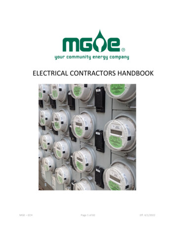
ELECTRICAL CONTRACTORS HANDBOOKMGE – ECHPage 1 of 82Eff. 4/1/2022
Table of Contents1General Information . 32Character of Service . 83Service Facilities . 94Overhead Service Drops and Underground Service Laterals (Non-Network). 105Meters and Meter Equipment . 116Non-Network Overhead and Underground Distribution Extensions. 157Low-Voltage AC Network System . 198Rights and Responsibilities. 219Motors and Starting Requirements . 2310Power Factor Correction Rule . 2511Emergency Electric Service . 2612Customer-Owned Optional Standby Electric Generating Equipment . 2713Customer-Owned Parallel Distributed Energy Resources (DER). 2814Charges for Overhead Drops and Underground Service Laterals . 3015MGE Electric Distribution Engineering Department Directory . 3116Service Details . 3217Meter Numbers. 70MGE – ECHPage 2 of 82Eff. 4/1/2022
1General Information1.1IntroductionThis Madison Gas and Electric Company (MGE) Electrical Contractors' Handbook gives contractors,architects, engineers, and customers answers to common questions about residential, commercial,and industrial electrical services and metering installations.Any rules or regulations conform with and supplement local, municipal, and State of Wisconsinelectrical codes.For a complete legal and definitive description of all procedures, regulations, and responsibilities,refer to the Madison Gas and Electric Company Rates and Service Rules Manual available fromMGE and on file with the Public Service Commission of Wisconsin (PSCW).1.2Definitions1.2.1Service Drop refers to the overhead conductors between the distribution pole and the point ofattachment at the applicant's service entrance facility. A Service Drop is normally located on thecustomer's property and is of secondary voltage.Service Lateral refers to the underground conductors between the Distribution System,including any risers on a pole or other structure and the customer's service entrance facility. AService Lateral is normally located on the customer's property and is of secondary voltage.Distribution System includes all primary lines, secondary lines, transformers, and controlequipment necessary to provide points of connection with Service Drops or Service Laterals.Though located on customer property, transformers and associated equipment are part ofMGE's Distribution System.Normally, the Distribution System is located within an electric utility easement on privateproperty or on public streets, alleys, and roads so that it may be extended to other applicants.Property owners grant easements without cost to MGE.Transmission System includes all overhead lines, underground lines, and transformers operatingat or above 69,000 volts line-to-line or 39,800 volts line-to-ground. In addition, it includes allcontrol equipment used to operate these facilities.1.2.21.2.31.2.41.3Determine Location of Electric Facilities in Area of Proposed WorkPrior to performing any excavation, grading, blasting, construction, erection, or demolition workwithin MGE's service territory, call Diggers Hotline at 1-800-242-8511 or 811 or visitdiggershotline.com to obtain the location of our facilities and other participating utility facilities.MGE will provide facility location prints and field-locating services promptly.It is necessary for you to place the request 72 hours (three working days) in advance of nonemergency excavation as required in Section 182.0175 of the Wisconsin Statutes. Make anadditional request for location of facilities when the project is delayed or interrupted for ten ormore workdays or when changes are made in the proposed construction.You, as the contractor, are responsible for maintaining the stakes and markings placed by ourlocating personnel who mark the location of our existing facilities. If the markings are inadvertentlydestroyed or additional work is to be performed which requires re-staking of your project area, callDiggers Hotline at 1-800-242-8511 or 811 again.MGE – ECH Chapter 1Page 3 of 82Eff. 4/1/2022
When emergency excavation is necessary, call Diggers Hotline at 1-800-242-8511 or 811 duringnormal working hours. If there is an emergency outside of normal working hours, call 608-252-7111or 1-800-245-1123. MGE locating personnel will respond promptly and field locate our facilities foryou.An emergency location is defined as an underground locate request where excavating or demolitionmust begin prior to the standard three business days. An emergency exists only when one or moreof the following conditions exists:The unforeseen excavation which, if not performed, could result in the loss of life or limb.The excavation is required to repair a service outage. Excavation is required prior to three business days in order to prevent property damage. An unstable condition exists which may result in any of the conditions listed above (forexample, a leak in any service main or a fault in a primary or secondary wire and/or cable).When calling in an emergency excavation, inform the operator that an emergency situationexists and be prepared to explain which of the above conditions is in effect. The operator willprepare the ticket for immediate transmission and issue a start date equal to the time theexcavation is scheduled to commence.Placement of Facilities Adjacent to Electric DistributionFacilities being installed to cross existing underground electric distribution wires and/or conduit(operating at less than 39,800 volts to ground) at or near an angle of 90 degrees must maintain aminimum clearance of 6 inches. Contact MGE Engineering for review of the circumstancesinvolved in all these installations.Facilities that are to be installed parallel or nearly parallel to existing underground electricdistribution wires and/or conduit must provide a minimum of 12 inches of horizontal clearance.Unless it is planned to shore the ditch, increase the horizontal clearance 12 inches for each 12inches of depth of ditch below the level of the existing facilities.Contact MGE Engineering for review of the circumstances involved in all these installations.Above ground appurtenances, poles, buildings, etc., placed adjacent to overhead electricfacilities must conform to the clearances specified in the Wisconsin Administrative Code whichhas adopted, with some changes, the National Electric Safety Code and the National ElectricCode. If you have any question as to the clearance required, call MGE Engineering.If you are engineering a project or planning to bid on a project that may jeopardize existing MGEelectric facilities, call MGE at 608-252-7373 for assistance in providing relocation costs orcoordination of work activities.Placement of Facilities Adjacent to Electric TransmissionIf you are engineering a project or planning to bid on a project which may jeopardize existingelectric transmission facilities, call for assistance in providing relocation costs or coordination ofwork activities. ATC can be reached at Local: (262) 506-6700 and Toll free: (866) 899-3204.Excavation Near Underground Electric FacilitiesAfter the location of all underground electric facilities has been determined, make sure allmachine operators, foremen, and supervisors on the project are aware of their location. Do notforget new people on the job. They will not know the facilities are there unless you tell them.Excavations crossing or adjacent to electric facilities must conform with all applicable federal,state, and local codes and ordinances. 1.3.11.3.21.3.3MGE – ECH Chapter 1Page 4 of 82Eff. 4/1/2022
1.3.4Use caution when excavating near underground electric facilities to ensure no damage isinflicted to the cable jacketing or concentric neutral wires. Do not use poured concrete within 18inches of underground electric cables due to the deterioration it causes to the insulationmedium on the cables. This deterioration is not immediate but occurs over time. The length oftime to cable failure depends on many factors including strength of concrete, water table, andother environmental conditions.Do not use any power-operated excavating or earth-moving equipment within 18 inches of theunderground facility and the cutting edge of the tool. This is covered in Section 182.0175 of theWisconsin Statutes. If you are within 18 inches of the underground facility, it will be necessary tohand dig around it to prevent damage.Shoring, sloping, and/or some equivalent means meeting OSHA requirements must be used toprevent caving or movement of ditch banks adjacent to underground electric facilities.Provide proper supports when excavating near or under electric facilities. These supports arenot to damage the facilities they are supporting. Before performing any work where existingMGE electric facilities need to be supported, call MGE at 608-252-7373 for assistance andcoordination of work activities.Do not attempt to bore past an underground electric facility without determining if sufficientclearance exists. It is recommended that facilities be exposed as necessary to prevent damage.Note: Even a simple underground electric service is capable of causing severe injury and/ordeath if handled improperly.On all excavations adjacent to underground electric transmission facilities, contact the facilityowner before performing any work. ATC can be reached at Local: (262) 506-6700 and Toll free:(866) 899-3204.Construction Near Overhead Electric FacilitiesAfter the location of overhead electric facilities has been determined, make sure all machineoperators, foremen, and supervisors on the project are aware of their locations. Do not considerany overhead wire to be insulated. Do not park tall equipment or create a load/unload areaunder overhead conductors.Any time you leave the traveled portion of a road, you must consider that the overhead lineclearance may not be sufficient for your tall equipment. Any overhead electric conductorincluding 120/240-volt service is sufficient to cause severe injury and/or death if contacted.OSHA requires that you maintain a minimum safety clearance of 10 feet when using backhoeexcavators or boom lifts, erecting scaffolding, raising dump boxes on vehicles, and during use ofany tall equipment near overhead electric facilities.Contact the MGE Construction Department if crane operations could get closer than 20 feet tothe overhead electric facilities. The crane operator shall comply with OSHA 1926.1408 and1926.1409 if the crane could get closer than 20 feet to an overhead conductor.When excavating is to be performed adjacent to overhead poles and/or structures, leave aminimum of 2 feet of ground at the ground line of the pole along with a one-to-one slope fromthat point to the new grade level. Other arrangements can be made by contacting MGEConstruction Engineering.If you believe any structure, permanent or temporary, will be in conflict or in close proximity tooverhead conductors or a Service Drop, contact MGE Construction Engineering.MGE – ECH Chapter 1Page 5 of 82Eff. 4/1/2022
1.3.5Blasting Near Any Electric FacilityDo not perform blasting operations in the vicinity of any MGE facilities until MGE has beennotified and provided confirmation that the work can safely proceed. MGE will ensure thatprotection of all MGE facilities have been taken. Such measures will include preplannedemergency procedures.When blasting operations are performed, they shall be done only by a licensed blaster andstrictly in accordance with all local, state, and federal codes and regulations. Liability for anydamage remains the responsibility of the party performing the blasting.1.3.6Backfilling in the Area Near Underground Electric FacilitiesReport any scrapes, cuts, abrasions, or broken underground cables and/or conduit that haveoccurred while the facilities are exposed. Call MGE at 608-252-7111 to report any damage andhave the underground facilities inspected prior to backfilling. MGE will inspect and makenecessary repairs as warranted.Where excavation removes the original ground under concrete conduit and manhole systems,backfill the area below this facility with pit run or washed sand compacted mechanically in 6inch lifts to provide the same or better support than was there prior to the excavation. Compactthe backfill above the facilities by mechanical compaction in accordance with MGEspecifications.Before performing any work that entails digging under MGE electric conduit systems, call MGEat 608-252-7373 for assistance and coordination of work activities.1.3.7Grading and Landscaping WorkWhen grading or landscaping work is planned which involves the lowering of existing grades,determine the depth of the underground facilities in the area by hand excavation under MGEguidance before the work commences. Raising or lowering of underground electric facilities dueto grade changes is at the cost of the party changing the grade.1.4Certificate of Inspection Required Before ConnectionMGE requires a Certificate of Inspection from the authorized electrical inspector of theappropriate town, village, or city before connecting new or modified services.If the area or facility is not required by law to have an authorized electrical inspector, MGE willaccept, in lieu of the Certificate of Inspection, a signed and notarized affidavit from the electricalcontractor which certifies the wiring conforms to the Wisconsin State Electrical Code.1.5Before Applying for Service ConnectionsService connections and extensions are made in accordance with filed rules and regulations.However, MGE recommends that before you apply for service or prepare wiring plans, you giveattention to the following:1.5.11.5.2Contact the MGE Electric Construction Engineering Department as soon as you begin planningfor your facility.ApplicationsApply for service as far in advance as possible of the date service is required. You may apply forservice at the MGE General Office Facility or struction/new-service-installationProvide the date your service is required.MGE – ECH Chapter 1Page 6 of 82Eff. 4/1/2022
Completely identify property locations including name, addresses, lot and block numbers, andprovide site plans when possible. Site plans should include the proposed service location as wellas the nearest transformer or utility pole.For commercial and industrial buildings, MGE needs the architect's and engineer's names andcontact information, the type of building, and the planned load.Customer-owned private underground facilities should be identified on site plans. In areas notserved by municipal sewer and water, include a copy of septic and water system prints. MGE isnot liable for damage caused to unmarked underground private heck with MGE about the availability of 120/208-volt or 277/480-volt three-phase, four-wireservice.Check the low-voltage network map (see NET-1) to determine if you are served by theunderground low-voltage network system which covers the downtown Madison area (see ECHChapter 7).Underground ServiceDepending on project location, certain municipalities may require underground electric services.Review Section 19.16 of the Madison General Ordinances entitled "Underground UtilityEntrance Facilities" concerning underground entrance requirements.MeteringWhen applying for service, submit a sheet detailing the quantities and sizes of all the proposedmeters for the project.Pad-mount Transformers in the Non-Network AreaCustomers with present or prospective loads of 75 KW or more must provide space for theinstallation of self-enclosed, pad-mounted transformers and switchgear with vehicle access andin accordance with Wisconsin State Electrical Code (PSC 114.317).Underground Vaults in the Network AreaCustomers with present or prospective loads of 75 KW or more must provide transformer vaultsapproved by MGE and meet all applicable specifications and governmental codes (see ECHChapter 7).New Residential or Commercial DevelopmentsCheck with the municipality for separate requirements, including electric and utilityfacility placement and streetlighting requirements for new plats.MGE – ECH Chapter 1Page 7 of 82Eff. 4/1/2022
2Character of ServiceMGE distributes electric current to residential, commercial, and network customers as follows:2.1Residential, Commercial, and NetworkTransformers supplied by MGE are typically available at 120/240 volts, 120/208 volts,277/480 volts, 120/208 (low-voltage network), and 277/480 (spot network). Transformersare standard ratio and standard impedance, single-phase and three-phase oil-cooled typesonly.2.2Residential and Commercial2.2.1Single-phase, 60-cycle alternating current is available at 120/240 volts, or, in specialcircumstances, 120/208 volts over a three-wire service.Customers outside the low-voltage network system who provide MGE with acceptable space fortransformer installations may obtain three-phase 120/208 volt or 277/480 volt four-wire servicesubject to the following minimum 15-minute demand: 120/208 volts, 75 KW 277/480 volts, 150 KW2.2.22.3Primary Voltage Metered Commercial Only2.3.12.3.2Three-phase, 60-cycle alternating current may be supplied at 2,400/4,160 volts for large powerinstallations over a four-wire service. This service is available at limited locations and at MGE'sdiscretion.Three-phase, 60-cycle alternating current at 7,970/13,800 volts over a four-wire service isavailable at limited locations and at MGE's discretion. A new primary-metered service shall take service at 7,970/13,800 volts four-wire ifavailable.2.4Network Only2.4.1Single-phase or three-phase, 60 cycle alternating current may be supplied at 120/208 volts overa three-wire or four-wire service, respectively.Three-phase, four-wire, 277/480 volt spot network service is provided only upon MGE's specificwritten approval where all of the following conditions are met: The customer requests it, The 15-minute demand exceeds 750 KW, Suitable multiple 13.8-KV circuits are available at the proposed site, and The customer provides necessary transformer space2.4.2MGE – ECH Chapter 2Page 8 of 82Eff. 4/1/2022
3Service Facilities3.1Service Entrance SpecificationsMGE specifies, in writing, customers' service entrance locations, including service entranceconduit sizes, quantity, and termination points.3.23.2.1Electrical ServicesMGE supplies electrical service in accordance with all applicable national, state, and localelectrical codes, including the NEC, WI PSC 113, and WI SPS 316.230.For each customer's building or premise, MGE supplies: No more than one Service Drop or Service Lateral; No more than one class of service; No more than one meter; and Service to no more than one service entrance, main disconnect, or MGE-approved meteringdevice.Exceptions: When more than one point of delivery is necessary because of voltage regulation,governmental requirements, or regulatory orders. When more than one Service Drop or Service Lateral of the same class of service isnecessary to meet the load requirements of large installations. When row houses and other multiple occupancy buildings comply with the State electricalcode by having areas separated by fire walls. When an additional service or meter may be required to accommodate special approvedservice rates. Where multiple-occupancy buildings require separate meters for individual tenants, morethan one meter is allowed. When total load exceeds 800 KW for single-metered commercial customers, two classes ofservice are available.MGE – ECH Chapter 3Page 9 of 82Eff. 4/1/2022
4Overhead Service Drops and Underground Service Laterals(Non-Network)4.1Requirements4.1.1MGE specifies, in writing, customers' service entrance locations, including service entranceconduit sizes, quantity, and termination points.MGE installs, owns, and maintains all Service Drops and Service Laterals.4.1.24.1.24.1.34.2For overhead Service Drops, the applicant's service entrance facility must be located at a pointreadily accessible to the Distribution System and at a height to provide for proper codeclearance of the Service Drop wire.Where it is necessary to cross adjacent property, the applicant must make arrangements withthe third-party landowner for MGE to obtain the proper easements.The applicant must also obtain the proper location for the service masthead from MGE andprovide suitable anchorage for supporting the Service Drop on the building.If the present or prospective load is 75 KW or more, MGE specifies that the applicant mustprovide space for the installation of self-enclosed, pad-mounted transformers and switchgearwith vehicle access, and in accordance with Wisconsin State Electrical Code (PSC 114.317).Location of ServiceAll Service Drops and Service Laterals will be extended from the MGE Distribution System to thecustomer's service entrance facility over the most direct and properly engineered route asdetermined by MGE. The customer's service entrance point will be located outside as specifiedby MGE.4.3Customer Contribution for Service FacilitiesSingle-phase service drops, three-phase service drops, single-phase service laterals up to 120’,and three-phase service laterals up to 50’ will be installed at no cost to the customer. Thecustomer will pay an incremental cost for single-phase service laterals in excess of 120’ andthree-phase service laterals in excess of 50’. Distances are measured from the DistributionSystem to the customer’s service entrance facility using the most direct and properly engineeredroute as determined by MGE. See the Electric Service Routes page for costs and methods fordetermining these charges.4.4Rights-of-Way, Easements, and Maintenance of GradeThe applicant or developer is responsible for furnishing MGE with rights-of-way and easementswithin a reasonable time frame to meet service requirements. The right-of-way must be clearedof trees, stumps, and other obstructions prior to installation. After installation, the right-of-waymay be used by the grantor in any way that does not interfere with MGE's ability to maintain itselectrical facilities at any time.The right-of-way must be graded within 6 inches of final grade and be maintained by theapplicant during utility construction. Future changes or relocations of MGE facilities due tochanges in grade will be at the property owner's expense.MGE – ECH Chapter 4Page 10 of 82Eff. 4/1/2022
5Meters and Meter Equipment5.1Customer ResponsibilityCustomers are responsible for furnishing and installing all wiring for meter installations,including such associated facilities as meter sockets, meter enclosures, meter test blockenclosures, current transformer enclosures, etc., as required for the appropriate type ofmetering installations specified in this section. Meter sockets must be approved by MGE for theparticular type of service and comply with local and state codes.5.2Access, Mounting and Location5.2.1Any residentially zoned buildings, including single-family and two-family homes, must have themeter installation in an accessible area outside the structure (see SER-1). Other buildings thatare not easily accessible to MGE personnel during normal working hours must also have anoutside meter installation.For commercially zoned multiple-unit residential, commercial, and industrial customers such asapartments, office buildings, stores, and factories, meters should be located outside (see SER-1)or in an electric room on an exterior wall with exterior access (outside way) (see SER-2). Anyother location must be pre-approved by MGE Engineering (see SER-3).On installations with multiple meters, meters must be grouped together and have theassociated disconnects and sockets marked to indicate the portions of the buildings supplied byeach meter. Free-standing meter pedestals not attached to a structure, such as for a trafficcontroller, shall be labeled with the service address. The service address label for eachdisconnect and/or meter socket shall be made of the following material: rigid engraved plastic engraved self-sticking brass engraved self-sticking aluminumUnless approved by MGE engineering, meters must be grouped on the same outside wall or inthe same electric room or area.Associated disconnects, CT cabinets, and meter sockets must be located on the same area of thewall or in the same electric room and may not be in separate rooms.In outdoor installations, locate meters where access won't promote damage to lawns, gardens,or shrubbery.Meters must be installed in accessible areas with a minimum of 3 feet of frontal clearance soMGE personnel can read and test them without causing customer inconvenience or a safetyhazard to MGE personnel. Depending on the installation, the minimum clearance may need tobe increased. See NEC 100.26 for more information.Meter rooms must be kept clear of debris and are not to be used for storage.Where meters are mounted side by side, leave at least a 7-inch space between each meter andthe nearest adjacent piece of equipment to permit testing and adjusting. Use of a 6-inch spacesection may be required to meet this requirement.Meters mounted inside or outside must be between 4 and 6 feet above final grade. Final grademust be established before the meters can be set.Exception: Pedestal-type meter sockets and multiple meter stacks must be between 3 and 6 feetabove final grade for outside .2.9MGE – ECH Chapter 5Page 11 of 82Eff. 4/1/2022
5.2.105.2.115.2.125.2.13Exception: Multiple meter stacks must be between 2 and 6 feet above final grade for insideinstallations and between 2.5 and 6 feet above final grade for outside installations.Meters must be located in such a manner as not to interfere with gas piping or gas metering(see MIS-2 to determine minimum clearance required).Meter mountings must be secure, free of vibrations, and installed plumb.Meters must be free from unusual temperature and moisture conditions.In areas subject to damage from falling ice or debris, installation of an ice shield is required (seeMIS-10).5.3Removal and Relocation5.3.15.3.2Only MGE employees may set, remove, or relocate meters.On jobs where it is necessary to temporarily disconnect or relocate a meter, contact MGE NewConstruction Services at 608-252-7373 at least two days to one week before the work is to bedone.Where new wiring has been done, inspection permits and/or signed and notarized affidavits arerequired before MGE will set the meter.MGE will seal all meter switches, meter sockets, enclosures, and meters at the time ofinstallation. Notify MGE prior to removal of seals for construction and maintenance purposes. Ifa seal is broken in the event of an emergency, contact the MGE Electric Meter Shop at 608-2524721 within 48 hours for 3ResidentialNote: In the network area, a switch-fuse-meter sequence is required.Horn-type bypass or manual sealable lever-operated bypass for self-contained ringless metersockets with a meter-switch-fuse sequence for: Single-phase installations of 320 amperes or less (see RES-1 and RES-2). Multiple metering installations for two to six units (see RES-4). Multiple metering installations for more than six units (see RES-5).Transformer-rated meter sockets and current transformers may require meter-switch-fusesequence for: Single-phase installations over 320 amperes of actual load (see RES-3). Three-phase installations over 200 amperes of actual load (see COM-3).Commercial and IndustrialNote: In the network area, a switch-fuse-meter sequence is required.Manual sealable, lever-operated bypass, self-contained heavy-duty jaw-released meter socketswith a meter-switch-fuse sequence for: Single-phase and three-phase installations of 200 amperes or less (see COM-1 and COM-2).Transformer-rated meter sockets and current transformers for single-metered customers withmeter-switch-fuse sequence for: Single-phase installations over 200 amperes for commercial and industrial customers (seeCOM-3, COM-4, and COM-5). Three-phase installations over 200 amperes for commercial and industrial customers (seeCOM-3, COM-4, and COM-5).For multiple-meter installations in commercial and industrial buildings, a main buildingdisconnect is required (see COM-6 and COM-7).MGE – ECH Chapter 1Page 12 of 82Eff. 4/1/2022
5.5.45.65.6.15.6.25.6.35.6.45.6.5In a multi-meter installation, all 277/480V meters and all CT rated meters will require a switchfuse-meter setup (cold-sequence).Three-phase,
This Madison Gas and Electric Company (MGE) Electrical Contractors' Handbook gives contractors, architects, engineers, and customers answers to common questions about residential, commercial, and industrial

