Transcription
Principles for protection of BelowGround Structures against waterfrom the groundBelow Ground WaterproofingPrimary reference British Standard BS8102: 2009Waterproofing DesignPerformance Solutionfor Below GroundApplication andproduct optionsPractical notes
Principles for protection of BelowGround Structures against waterfrom the groundBelow Ground WaterproofingThis summary is an adaption of the British Standard BS8102: 2009,modified for Australian conditions, tailored more specifically toMelbourne, Victoria.Applicable to NCC Building Classes : 1 through to 10Climate Zone :6Wind Class:N1Contents:1. Terms and Definitions2. Design Philosophy3. Site Evaluation4. Water – Resisting Design5. General Construction Issues6. Waterproofing Type A (Barrier) Protection7. Waterproofing Type B (Structural Integral) Protection8. Waterproofing Type C (Drained) Protection9. Remedial Measures.PRACTICAL CONSIDERATION NOTESPage 2
Page 3Below Ground Waterproofing
1. Terms and DefinitionsCavity drain membranedimpled, flexible, high-density polymer sheet, which can be placed againstthe internal face of a structure after construction and is designed tointercept water penetrating the structure and direct it to a drainagesystem.Below Ground WaterproofingCur-off wallembedded retaining wall designed to surround and seal-off an area, toinhibit water inflow from the surrounding areaDamp areaarea which, when touched, might leave a light film of moisture on the handbut no droplets of water (i.e. beading)Embedded retaining wallwall used to support the sides of an excavation, installed in advance andpenetrating below the lowest level of the below ground constructionGround barrierimpermeable barrier between the structure and the ground intended toprevent or impede the ingress of water, dampness, radon, methane andother ground gases and contaminantsLoading coatlayer of material designed to hold a Type A waterproofing material in placewhen resisting water pressurePerched water tablereservoir of water in the ground maintained permanently or temporarilyabove the standing water level in the ground below it, and is caused bythe presence of an impervious soil or a stratum of low permeabilitySeepageslow transmission of water through discrete pathways of a structureTankingapplication of an appropriate waterproofing barrier to the walls, the baseslab and, where relevent, the roof of the below ground structure, such thatthe entire envelope of the structure below ground is protected againstwater ingressPage 4
Type A (barrier) protectionprotection against water ingress which is dependent on a separate barriersystem applied to the structureType B (structurally integral) protectionprotection against water ingress which is provided by the structureBelow Ground WaterproofingType C (drained) protectionprotection against water ingress into usable spaces which is provided bythe incorporation of an appropriate internal water management systemVapour checkmembrane or other element that restricts the transmission of watervapour.Waterproofimpervious to water (also known as “watertight”)Waterproofingapplication of waterproofing/water-resisting materialsWaterproofing barriermaterial that does not permit the transmission of free water, but mightallow some water vapour permeabilityWaterproofing systemmaterials and methods used to protect a structure from water ingress andmight also provide resistance to the diffusion of water vapourWater resistanceability of a material to resist water penetrationWaterstopmaterial designed to inhibit the transmission of water through joints in thestructureWater vapourwater in its gaseous stateWater vapour resistanceability of a material to resist water vapour penetrationPage 5
2. Design philosophyBelow Ground WaterproofingGeneralEffective planning for any below ground structures requires immediateconsideration of the site and neighbouring environment a conditions. Thisshould incorporate investigation of the soil quality and the possible presenceof groundwater, gases and any unwanted contaminants.When designing new structures, the structural design, overallweatherproofing, waterproofing and construction process are consideredtogether, as they generally interact.It is proposed that during the design process, plus all stages of theconstruction process, the designers, specialists, manufacturers/suppliersand installing contractors establish and maintain effective channels ofcommunication.Principle considerationsIn order to develop a robust design for protecting a structure againstgroundwater, the following factors should be assessed;a. The likely highest level of the water table, the drainage characteristics ofthe soil and other site-specific propertiesb. The appropriate waterproofing measures i.e. Type A, B or C protectionand, where necessary, external drainage based on:1.the results of the site evaluation, including the classification ofthe water table2.the intended use of the structure, with consideration given toany requirement for future flexibility.c. The appropriate type of primary waterproofing systemd. Should defects occur, allow for potential remedial measuresNote: The waterproofing specialist could be the manufacturer or materialsupplier whom has the relevant expertise.Page 6
Design Flow ChartINITIAL INFORMATIONDesign philosophy Design teamBelow Ground WaterproofingSite evaluation Desk study Risk assessment Water table classificationReview of structure Type Intended use Foundation form and design Construction methodologySTRUCTURAL DESIGN CONSIDERATIONSSELECTION OF TYPE A, B OR CWATERPROOFING PROTECTIONIS COMBINED PROTECTION NECESSARY?SELECTION OF PRIMARYWATERPROOFING SYSTEMHAS BUILDABILITY BEEN CONSIDERED?NOHAS REPAIRABILITY BEEN ADDRESSED?YESSOLUTIONPage 7
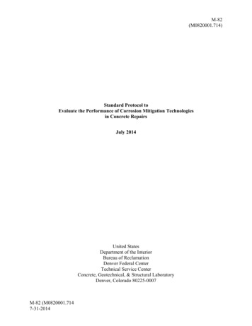
3. Site EvaluationsBelow Ground WaterproofingDesk studythe desk study should at least cover;a. Assessment of geology and hydrogeology, including soil permeabilities,flood risk, radon, methane and other ground gases and contaminants.b. To assess the topography of the surrounding ground in relation to thebelow ground structurec. To establish the likely highest level of the water table and the potentialfor the occurrence of a perched water table; andd. To identify any missing ground and groundwater information, whichshould then be obtained by site investigation.Risk assessmentA risk assessment should be carried out which considers the long-termwater pressures, the effects of surface water infiltration and the use ofexternal drainage and cut-off walls.Risk assessment should also consider;a. The effects of climate change, burst water mains and sewers, adjacenttrees, sulfates, radon, methane and other ground gases andcontaminates; andb. Where external drainage is proposed, the effects of drawdown onadjacent structures, the potential silting of drainage and biofoulingissuesEven when the site investigation indicates dry conditions, the risk of somewaterlogging in the future should be assumedWater table classificationAssessment of water table should be classified into three categories: High – where the water table or perched water table is assessed to bepermanently above the underside of the base slab Low – where the water table is assessed to be permanently below theunderside of the base slab Variable – where the water table fluctuatesInspection of existing structuresThe code states the need to inspect existing structures carefully before anyrisk assessment is completed and the waterproofing system is specified orinstalled. Typical issues: a change in ground water moisture content; theremains of former buildings or structures; changes in soil strata affectingfoundation movement.Page 8
Below Ground WaterproofingCharacteristics of soils which affect basement constructionPage 9
4. Water-Resisting DesignGroundwater DesignWaterproofing measures should be designed on the basis of water to thefull height of the retained ground at some time during the structure’s lifewhere:Below Ground Waterproofinga) No detailed geological or hydrogeological assessment has beenundertaken;b) The results of the soil investigations are inconclusive with respect togroundwater;c) The ground drainage characteristics are unreliable;d) The drainage measures (internal or external) are unreliable or unmaintainable and infiltration cannot be controlled.Consideration from the following sources of water ingress protectionshould be considered: Inflow of surface water: ranging from rain percolation to inundation ofwater from a burst water mains The water pressure acting on the external retaining wall system The water pressure below the base slabTypes of Waterproofing ProtectionBS 8102 describes three types of waterproofing protection:Type A – Barrier Protection: where the structure has limited integralprotection against water penetration and therefore relies permanently on awaterproofing membrane to keep water out.Page 10
Below Ground WaterproofingType B – Structurally integral Protection: where the structure itself isconstructed as an integral water-resistant shell.Page 11
Below Ground WaterproofingType C – Drained Protection: where the structure provides primaryresistance against penetration and incorporates a drained cavity within thebasement structure. There is a permanent reliance on this cavity to collectgroundwater seepage through the structure and direct it to drains or asump for removal by drainage or pumping.Page 12
Combined/Combination SystemsConsideration can also be given to the use of combined systems (e.g.type A and type B and type C or type B and type C) where the assessedrisk are deemed to be high, where consequences of defects or inadequateworkmanship are high, or where additional vapour checks are requiredwhere water vapour penetration can occur.Below Ground WaterproofingWater table classification and grades of waterproofing protectionWhen selecting a type of waterproofing protection the following chartsoutline options, in conjunction with these points.a) During the life of the structure, some degree of groundwater pressureis likely to build up against the chosen waterproofing systemb) Cracking or defective construction joints can provide path for wateringressc) Water ingress can occur where there is groundwater pressured) There are a number of risks associated with not carrying out plannedmaintenance for structures with Type C protection. .e.g. pump failurePage 13
Below Ground WaterproofingWatertightness – Grade 1 , 2 & 3Grade 1Grade 2Car ParkingPlant Rooms/ workshops(Excluding electrical equipment)retail storage areasPlant Rooms/ workshops(with electrical equipment)SOME SEEPAGE AND DAMPPATCHES ARE TOLERABLENO WATER PENETRATIONBUT SOME MOISTUREVAPOUR TOLERABLEGrade 3ResidentialOfficesLeisure Centres etcArchivesDRY ENVIRONMENTPage 14
Below Ground WaterproofingSub-surface drainageWhere sub- surface drainage is deemed necessary to lower the potentialfor hydrostatic pressure on the waterproofing system and lesson the riskof water ingress through defects, it should be provided by one of thefollowing methods:a) Permeable granular fill;b) No-fines or hollow blockwork;c) Geosynthetic drainage composite;d) Under slab drainagePage 15
Ground GasesThe insertion of a ground barrier for the prevention or radon, methane andother ground gases and contaminants from entering a structure should beconsidered in the design, choice of materials and installation of anywaterproofing system.Below Ground Waterproofing5. General Construction IssuesSite de-wateringWhere appropriate, the site should be de-watered at least until such timeas the below ground structure and waterproofing is completed.On open sites, where any adjacent structures are sufficiently remote to beunaffected by groundwater lowering, de-watering or pumping fromcarefully arranged sumps with appropriate drainage channels should becontinuous while the laying of any waterproofing barrier material is inprogress and until all loading coats have fully cured. Also ensuring thestructure itself has developed sufficient strength to resist the full waterpressure.Structural ElementsForms of construction to receive below ground waterproofing protectionmay include the following.a) Walls – constructed from:i. Masonry (plain or reinforced brick or block)ii. Precast concreteiii. In-situ concrete, either cast in form or embedded wallsiv. Steel or concrete piles in embedded wallsb) Base slab – constructed from concrete cast in situ, plain or reinforced,raft or other formc) Roof, where applicable – constructed from reinforced in-situ concrete,precast concrete with an in-situ topping, or a steel composite slab, raftor other form.NB: refer to National Construction Code (NCC / ABC) ; AS3600 ConcreteStructures and AS3700 Masonry StructuresPage 16
6. Waterproofing Type A – Barrier ProtectionBelow Ground WaterproofingGeneralStructures using Type A – Barrier Protection are normally constructed ofconcrete or masonry. Deeper structures are of concrete construction.Steel can also form part of the construction as temporary sheet piling.Barrier protection design should be based on an evaluation of:a) The nature of the substrateb) The likely overall and local movements that might cause distress in thewaterproofing barrierc) The ability of the barrier system to accommodate these movementsd) The essential characteristics of the waterproofing systeme) The need for external or internal applicationf) The effects of environmental contaminantsMaterials for Barrier WaterproofingThe waterproofing barrier for Type A protection should be installed in oneof the following locations;i. On the exterior face of walls or slabs (external waterproofing)ii. On some external source of support (reverse waterproofing)iii. Within the structure (sandwich waterproofing)iv. On the interior face of perimeter walls (internal waterproofing)All barriers should be installed strictly in accordance with themanufacturer’s instructions.Type of BarrierDescriptionApplicationBonded sheetmembranesBitumen based sheet membranesapplied hot or coldComposite sheet membranesCan be applied externallyor sandwichedLiquid AppliedmembranesMany types of membranesCovered by AS4858Can be applied externallyor sandwichedGeosynthetic clayliners (Bentonite)Comprising of bentonite with single ordual carrier materialCan be applied externallyor sandwichedMastic asphaltmembranesThese are applied in three coats as ahot liquidCan be applied externallyor sandwichedCementitiouscrystallizationUsed as a additive or applied as acoating to surfacesCan be applied internallyor externallyCementitious multicoat rendersMulti-coats are resistant to liquid waterbut allow water vapour penetrationCan be applied internallyor externallyPage 17
7. Waterproofing Type B - Structural Integral ProtectionGeneralFor water and water vapour resistance, Type B protection relies upon thedesign and the materials incorporated into the external shell of thestructure itself.Below Ground WaterproofingMaterials for structurally integral protectionThe main considerations relate to concrete and steel design.Reinforced concrete structures may be designed and detailed specificallyto minimize water ingress with no additional protective measures.The following factors are considered as being of particular importance inachieving a water-resistance concrete structure:a)b)c)d)e)f)g)The design of the structure and materials specificationThe quality of workmanship in preparing and placing concreteCuringSite organisationThe condition of the formationMaterial storageThe close – fitting of formwork, the fixing of reinforcements andpreparation of jointsMaterials supporting concrete structures protection include;i. Reinforced and prestressed concrete (in-situ or precast)ii. Concrete containing waterproofing admixuresiii. Waterstops –typically passive sections embedded; hydrophilic stripsor crystalline growth compounds or post-injected systemsiv. Steel piles in either sheet or tubular form may be used as thepermanent structural wall in cases where the pile clutch interlocksystem between individual sections can be adequately sealed.Embedded Retaining WallsConstruction for deep structures may be either top down or bottom up, ora combination thereof. The construction method should determine the useand type of embedded piled walls.For all embedded retaining walls, whether concrete or steel, the jointbetween the base slab and the wall should be precisely detailed toachieve structural continuity consistent with the design.Page 18
8. Waterproofing Type C – Drained ProtectionBelow Ground WaterproofingType C waterproofing protection manages water that penetrates theexternal shell of a structure, by collecting it in a cavity formed between theexternal wall and an internal lining/wall. There is a permanent reliance onthis cavity to collect groundwater seepage and direct it to a suitabledischarge point, e.g. drains or a sump for removal by gravity drainage ormechanical pumping.Structural aspectsThe outer leaf of the exterior wall is to be capable of controlling the waterquantity that can pass through the structure, in order not to exceed thedrainage capacity of the system.Maintenance and CommissioningTo maximise the long term integrity and effectiveness of a waterproofingsystem incorporating Type C protection, the waterproofing system shouldbe designed for ongoing maintenance.Access points that allow routine maintenance to be incorporated in thedesign.Immediately after the installation of a cavity drain system, drainagechannels and sumps should be cleared out and tested. Pumping devisesshould be checked, tested and fully commissioned in accordance with themanufacturer’s instructions.Page 19
9. Remedial MeasuresThere can be many causes of seepage in new and existing structures,principally caused by ; poor design and/or specification; defectivematerials; defective workmanship; deterioration of the structure; or changein the external environment.Below Ground WaterproofingBefore any remedial action is taken, defects should be diagnosed toidentify the cause and extent of the failure. The correct diagnosis of thefault is of vital importance in establishing if the fault exist within the systemas a whole, or whether faults are localised.Where remedial works are required, the following measures should beconsidered:a) The installation of a tanking system or a drained cavityb) The installation of external drainagec) Localised works to the fabric of the structure (such as)i. Pressure or vacuum groutingGrouting to cut off seepage might repair isolated defects.However, where a large number of defects occur, it is moreeffective to prevent water ingress by other means. Manygrouting materials are available inclusive of: cement,bentonite, chemicals, resins, expansive polyurethane,modified rubber latexii Crack sealing with resin or cementitious mortarWhere structural continuity is not required, with nohydrostatic pressure against adhesion the following can sealagainst water ingress: cement grout; crystallisation systemsor low viscosity latex emulsionsiii Crack filling by pressure or vacuum injectionPressure or vacuum injection can be used to fill and sealcracks and joints. Materials include multiple types of resins,SBR and cementitious groutsiv The replacement of locally defective materialWhere a relatively small number of well-separated defects inwalls or floors results in seepage, adequate repairs can beachieved by cutting out and replacing the defective areas.Page 21
PRACTICAL CONSIDERATION NOTESWhen considering waterproofing of basements, the principle of ‘what cango wrong – will go wrong’ applies. Thus a multi-strategy defence isimportant. The approach BS8102 takes by placing a vital emphasis on the‘design phase’ to identify the project issues and utilize a combination ofwaterproofing protection (Types A, B, C) to satisfy the level ofWatertightness required (Grade 1, 2, 3) is good practice.Below Ground WaterproofingNB: in Australia many projects have adopted standard building practices withoutsufficient consideration for the final building use. Grade 2 & 3 watertightness have beenattempted as post build modifications.1. The ‘Design Team’ should include a Waterproofing expert.Working with a waterproofing Consultant, Material Reseller orManufacturer will be great advantage.2. Main Waterproofing Systems.3. Notes on Foundation DesignStructures should be designed to keep foundations as simple as possible.Expansion joints and complicated shapes are best avoided, since they arepoints of weakness and require a lot of attention to detail. When decidingon the form of construction and waterproofing, paramount considerationfor ‘buildability’ and acceptable risk in relation to the cost of achievingdesired performance. Common foundation designs are covered by thefollowing diagram.Page 22
Below Ground Waterproofing4. Watertight ConcreteThere is often confusion between waterproof concrete and the relationshipto indicate the water tightness of the concrete structure.Waterproof concrete describes only the concrete mixture, which isimpermeable to water and focused on the concrete quality, often modifiedusing concrete admixtures such as superplasticizers, pore blockers andcrack healers.Defining ‘Watertightness of Concrete’ ,: “the water resistance of concreteis defined by the amount of water or moisture that emerges on the sideopposite to the water contact”Page 23
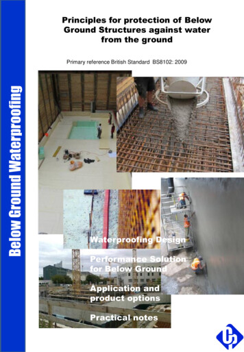
So What makes Watertight Concrete?Nearly all significant properties of concrete will be influenced by the watercontent and/or water/cement ratio.Below Ground Waterproofing The lower the water content; the higher the strength & consequentialE-modulus The lower the water content; the less porosity in the matrix & as aconsequence tighter the cement stone. The lower the water content; the less shrinkage and crack risk The lower the water content; the more critical the curing withconsequential risk of surface defects The lower the water content; the more critical the placing of the mix,with a higher potential of compaction defects.5. Joint DetailsOften the major weakness in a structure relates to joint sealing solutions.The two major types are: Construction Joints (non movement) Movement JointsCommon solutions include: Waterbars – using the Labyrinth Principle to provide for an enlargedway for the water around the waterbar, reducing water flow until it stops Hydrophilic Gasket – installing a swellable product to seal the joint Injection Systems - often repair applications , with many differentproduct performance characteristics Adhesive Sealing systems - a multitude of performance productsPage 20
Below Ground WaterproofingWaterbarHydrophilic GasketAdhesiveSealingPage 24
6. Membrane SystemsMost membrane systems relate to Type A – Barrier Protection. The basicprinciple of stopping the water getting into the structure. The mostcommon cause of failure of these systems relate to: Joins Application detailing Environmental suitability Relying on only one type of defence system.Below Ground WaterproofingThe basic types of membrane systems include: Lose laid membranes Bonded Membranes Liquid applied Membranes7. Other checksYour system need multiple defences inclusive of drainage and sometimesa negative tanking defence. It is very important to test your systemsbefore providing a ‘Deemed to satisfy’ compliance statement. Also allowfor on-going maintenance of your system.The following are some useful technical drawings supplied by AIW.Page 25
Page 26Below Ground Waterproofing
8. Compliance StructureCareful review of the compliance steps are required. However, in general,the NCC Vol 1 & 2 have no reference to “Below Ground Waterproofing”.As such, the NCC Compliance Structure will require a “Deemed-to-satisfy”solution.Outline Steps Required:Below Ground Waterproofinga) Determine the “Performance Requirements”The guidelines provided by BS 8102 help determine both the“Performance Requirements” and the “Performance Solution”, which islikely to have a “Deemed-to-satisfy” component.Key elements include; Establishing the Design Team (inclusive of a professionalengineer and waterproofing expert Rigorous testing and review of the waterproofing systemsolution in the design phase- Site Evaluations- Types of Waterproofing Protection- Level of Watertightness- Remedial applications Nomination of applicable NCC clauses and Australian Standardswhere “Performance Solutions” are identified Nomination of other International Standards which productcriteria meet. Nomination of Application Methods which are considered as“Deemed-to-satisfy”b) Certification with evidence of support from a “Professional Engineer”c) Detailed final design and specifications prepared for lodgement of aBuilding Permit.Page 27
Below Ground WaterproofingExample Defence Strategy options for WatertightnessGrade 1Typical Design OptionsCar ParkingPlant Rooms/ workshops(Excluding electrical equipment)External drainageSOME SEEPAGE AND DAMPPATCHES ARE TOLERABLEWaterproof Membrane and dampcourse externalstructureInternal Drainage, Sump pumpGrade 2Typical Design Optionsretail storage areasPlant Rooms/ workshops(with electrical equipment)External DrainageNO WATER PENETRATIONBUT SOME MOISTUREVAPOUR TOLERABLEWaterproof Membrane and dampcourse externalstructureWaterstop’s and concrete additives. Joint sealdetailing to concrete structureStructural internal drainageInternal negative tankingGrade 3ResidentialOfficesLeisure Centres etcArchivesDRY ENVIRONMENTTypical Design OptionsElaborate water table drainageWaterproof envelope case sub level structureWaterstop’s and concrete additives. Joint sealdetailing to concrete structureStructural internal drainageInternal negative tanking and moisture barriercoatingsPage 28
When designing new structures, the structural design, overall weatherproofing, waterproofing and construction process are considered together, as they generally interact. It is proposed that during the design process, plus all stages of the . BS 8102 describes