Transcription
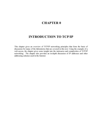
CHAPTER 0INTRODUCTION TO TCP/IPThis chapter gives an overview of TCP/IP networking principles that form the basis ofdiscussion for many of the laboratories that are covered in this text. Using the example of aweb access, the chapter gives some insight into the intricacies and complexities of TCP/IPnetworking. The chapter also provides an in-depth discussion of IP addresses and otheraddressing schemes used in the Internet.
TABLE OF CONTENTS1. A TCP/IP NETWORKING EXAMPLE12. THE TCP/IP PROTOCOL SUITE82.1. AN OVERVIEW OF THE TCP/IP PROTOCOL SUITE92.2. ENCAPSULATION AND DEMULTIPLEXING122.3. DIFFERENT VIEWS OF A NETWORK173. THE INTERNET203.1. A BRIEF HISTORY203.2. INFRASTRUCTURE OF THE INTERNET213.3. ADMINISTRATION AND STANDARD BODIES OF THE INTERNET244. ADDRESSES AND NUMBERS264.1. MEDIA ACCESS CONTROL (MAC) ADDRESSES264.2. PORT NUMBERS284.3. IP ADDRESSES284.3.1. SUBNETTING304.3.2. CLASSFUL ADDRESSES334.3.3. CLASSLESS INTER DOMAIN ROUTING (CIDR)364.3.4. THE FUTURE OF IP ADDRESSES385. APPLICATION LAYER PROTOCOLS385.1. FILE TRANSFER39
5.2. REMOTE LOGIN425.3. ELECTRONIC MAIL445.4. THE WEB475.5. RECENT APPLICATIONS52ii
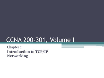
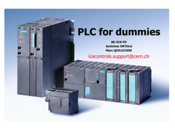
1. A TCP/IP Networking ExampleConsider a web browser (a web client) at a host with name Argon.cerf.edu (“Argon”) that makesa web access to a web server on a host with name Neon.cerf.edu (“Neon”).1 The web access isillustrated in Figure 0.1. Both hosts are connected to the Internet. The web access is a requestfor the home page of the web server with URL http://Neon.cerf.edu/index.html.Figure 0.1. A simple web request.We will explore what happens in the network when the web request is issued. We proceed, byfollowing the steps that are performed by network protocols until the first packet from Argonreaches the web server at Neon. An outline of the steps involved is given in the table below.The example in this section is based on real traffic measurements, however, the names of thehost have been changed.A web client and a web server are programs that interact with each other using the HypertextTransfer Protocol (HTTP). HTTP is a client-server protocol; the web client runs an HTTP clientprogram and the web server runs an HTTP server program. When a web client requests a webpage, the HTTP client sends an HTTP Request message to the HTTP server. When the webserver finds the web page, the HTTP server sends the page in an HTTP Reply message.HTTP uses the Transmission Control Protocol (TCP) to deliver data between the HTTP clientand the HTTP server. When the HTTP client at Argon wants to send an HTTP request, it mustfirst establish a TCP connection to the HTTP server at Neon (see Figure 0.2).1Throughout we use the term host refers to a computer , or more generally, to any end system of communications.
1. Web client at Argon starts an HTTP Request.2. Argon contacts its DNS server to translate the domain name “neon.cerf.edu” into IP address“128.143.71.21” and looks up the well-known port number of the web server (port 80).3. The HTTP client at Argon requestsa TCP connection to port 80 at IP address128.143.71.21.4. The TCP client at Argon requests its Internet Protocol (IP) to deliver an IP datagram withthe connection request to destination 128.143.71.21.5. The IP process at Argon decides that it cannot deliver the IP datagram directly, and decidesto send the IP datagram to its default gateway 128.143.137.1.6. The Address Resolution Protocol (ARP) at Argon sends an ARP request for the MACaddress of IP address 128.143.137.1.7. The ARP request is broadcast by the E thernet device driver at Argon to all devices on theEthernet network.8. The router with IP address 128.143.137.1 responds with an ARP Response to Argon whichincludes MAC address 00:e0:f9:23:a8:20.9. The IP process at Argon asks its Ethernet device driver tosend the IP datagram in anEthernet frame to MAC address 00:e0:f9:23:a8:20.10. Ethernet device driver at router with MAC address 00:e0:f9:23:a8:20 unpacks the IPdatagram, and passes it to its IP process.11. The IP process at the router decides that it can deliv er the IP datagram with destination128.143.137.21 directly (without the need of additional routers).12. The Address Resolution Protocol (ARP) at the router sends an ARP request for the MACaddress of IP address 128.143.137.21.13. The ARP request is broadcast by the Ethernet device driver at the router to all devices on theEthernet network.14. Neon (which has IP address 128.143.137.21) responds with an ARP Response to the routerwhich includes MAC address 00:20:af:03:98:28.15. The IP process at the router asks its Ethernet device driver to send the IP datagram in anEthernet frame to MAC address 00:20:af:03:98:28.16. The Ethernet device driver at Neon unpacks the IP datagram contained in the Ethernetframe, and passes it to its IP process.17. The IP process unpacks the TCP connection request contained in the IP datagram and passesit to the TCP server at port 80.18. The TCP server at port 80 processes the TCP connection request.Table 0.1. Overview of the steps of the networking example.0.2
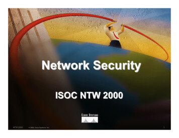
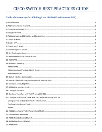
ArgonNeonHTTP clientHTTP request / HTTP responseHTTP serverTCP clientTCP connectionTCP serverFigure 0.2 An HTTP session invoking a TCP/IP transmissionBefore the HTTP client at Argon can ask the TCP protocol to establish a connection, it mustresolve an addressing issue. The TCP protocol expects that addresses be written in terms of anIP address and a port number. An IP address is a 32-bit identifier that uniquely identifies anetwork interface connected to the Internet. Every network interface that is connected to theInternet has an IP address. The IP address of Argon’s network interface is 128.143.137.144.Each byte (1 byte 8 bits2) of the IP address is written as a decimal number, and the fournumbers are separated by periods. A port number is a 16-bit address that can be used to identifyan application program on a system. Together, an IP address and a port number can uniquelyidentify an application on the Internet.neon.cerf.eduHTTP client128.143.71.21argon.cerf.eduDNS Server128.143.136.15Figure 0.3. A DNS lookup for the IP addressLe us now see how the HTTP client at Argon determines the IP address and the port number ofthe web server at Neon. The IP address is determined using an Internet-wide address translationservice, called the Domain Name System (DNS), that translates symbolic domain names, such asNeon.cerf.edu, into IP addresses, and vice versa. A host invokes the DNS service by sending arequest to its DNS server. The location of the DNS server of a host is part of the networkconfiguration of a host. Skipping over a lot of detail, Argon sends a query to its DNS server withthe domain name “Neon.cerf.edu”, and obtains in return the IP address for 128.143.71.21 (seeFigure 0.3).2Throughout this book, we use the convention that 1 byte is always 8 bits. The networking literature also uses the term “octet”to refer to a group of 8 bits.0.3
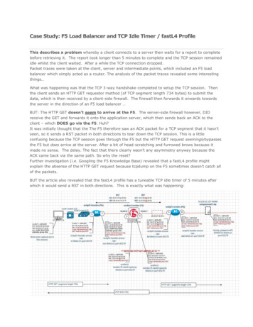
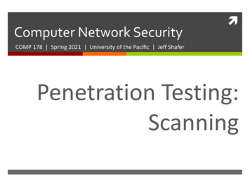
Once the IP address is obtained, determining the port number of the HTTP server at Neon issimple. On the Internet, the server programs of widely used applications have permanentlyassigned port number, called well-known port numbers, and are stored in a configuration file ofa host. The well-known port number of an HTTP server is port 80. When Argon contacts theHTTP server of Neon it assumes that the web server is reachable at port number 80.Now, the HTTP client at Argon has the information needed to establish a TCP connection, andrequests a TCP connection to port 80 at IP address 128.143.71.21. Like HTTP, TCP is a clientserver protocol. The party that initiates the connection is called the TCP client. The party that iswaiting for connection is called the TCP server. When a web server is started, the HTTP serversets up a TCP server that is waiting on the well-known port 80 for requests for TCPconnections. The details of establishing a TCP connection a covered later in this book. Here weonly note that the establishment of a TCP connection involves three steps: (1) the TCP clientsends a TCP connection request to the TCP server, (2) the TCP server responds to the request,(3) the TCP client acknowledges this response and starts to send data. Here, we only follow thefirst step of the connection establishment procedure, where TCP sends a connection request toport 80 of IP address 128.143.71.21. We point out that this connection request does not containany data. The HTTP request with the URL will be sent in the third step of the establishmentprocedure.We now follow the steps that are involved to deliver the TCP connection request from Argon toNeon. The TCP client at Argon asks IP, the Internet Protocol, to deliver the connection requestto IP address 128.143.71.21. IP takes the connection request, encapsulates it in an IP datagram(an IP datagram is the name of a packet in the Internet protocol), and delivers the IP datagram toNeon.The network shown in Figure 0.4 gives an overview of what is involved in delivering the IPdatagram from Argon to Neon. The figure shows that Argon and Neon are each connected to anEthernet local area network. The picture shows that the path (route), of an IP datagram fromArgon to Neon goes through a router which connects the two Ethernet. A router, also called IProuter or gateway, is a switching device with multiple network interface cards (NICs), whichtakes an IP datagram that arrives on one of its network interfaces and forwards the datagram ona different interface, with the intent to move the IP datagram closer to its destination. Theforwarding decision is based on a routing table, which lists the name of a network interface for aset of destination addresses. Note in Figure 0.4 that the router has a domain name and an IPaddress for each of its network interfaces.When Argon has the IP datagram for destination 128.143.71.21, it does not know the route thatthe IP datagram will take to its destination. The IP module at Argon merely determines if the IPdatagram can be delivered directly to Neon, or if the datagram must be send to a router. Adatagram can be delivered directly without the need for intermediate routers, if the sender andreceiver are both connected to the same local network. Argon makes a decision whether Neon ison the same local network, by comparing the IP address of Neon with its own IP address. Inthis particular case, Argon assumes that IP addresses that match its own IP address0.4
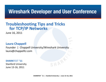
(128.143.137.144) in the first three bytes belong to interfaces that are on the same local networkas Argon, and all other IP addresses are not on the same local network. With this criterion, Neonis on a different local network and Argon tries to forward the IP datagram to its default gateway.The default gateway of a host is the IP address of a router, and is part of the networkconfiguration of any host. Argon’s default gateway is 128.143.137.1, with domain namerouter137.cerf.edu (“Router137”). Therefore, Argon sends the IP datagram to Router137.Figure 0.4. The route between Argon and Neon. The router in the center of the figure is referred to by any of the namesassociated its interfaces (“Router137” or “Router71”).To forward the IP datagram to the default gateway 128.143.137.1, Argon passes the IPdatagram to the Ethernet device driver of its network interface card. The device driver willinsert the IP datagram in an Ethernet frame (Ethernet packets are called frames), and transmitthe frame on the Ethernet network. However, Ethernet frames do not use IP addresses, but havean addressing scheme that is based on 48 bit long MAC (media access control) addresses. MACaddresses are written in hexadecimal notation, where each byte is separated by a colon or ahyphen. For example, Argon’s MAC address is 00:a0:24:71:e4:44. Each Ethernet framecontains the MAC addresses of the source and the destination of the frame. Before IP can passthe datagram to the Ethernet device driver, it must find out the MAC address that corresponds toIP address 128.143.137.1. The translation between IP addresses and MAC addresses is donewith the help of the Address Resolution Protocol (ARP).The translation of addresses using ARP and the subsequent transmission of the frame that holdsthe IP datagram steps are shown in Figure 0.5. First, Argon sends out an ARP message of the0.5
form “What is the MAC address of 128.143.137.1?”. The ARP message is sent in an Ethernetframe that is broadcast to all Ethernet devices on the same network. When Router137, whichhas IP address 128.143.137.1, receives the ARP message, it responds with an ARP message thatstates “IP address 128.143.137.1 belongs to MAC address 00:e0:f9:23:a8:20”. Finally, whenArgon receives this message, it passes the MAC address of the default gateway together with theIP datagram to the device driver and transmits the frame. In total, three Ethernet frames aretransmitted on the Ethernet network. (We note that subsequent transmissions of IP datagramsfrom Argon to Router137 do not require ARP messages. Argon keeps a list of known MACaddresses in a local table.)Figure 0.5. Ethernet frames transmitted to deliver the IP datagram to router137.cerf.edu.When Router137 receives the Ethernet frame from Argon, it first extracts the IP datagram andpasses the datagram to the IP module. Once Router137 receives the IP datagram from Argon, itmakes a similar decision as Argon, that is, it determines if the datagram can be forwardeddirectly to Neon or it selects a router from its local routing table and forwards the packet toanother router. Router137 has multiple network interfaces, and, therefore, checks if thedestination of the IP datagram is directly through any of its interfaces. To determine if a node islocally reachable, the router tries to match the first three bytes of the IP address of Neon, whichis included in the IP datagram, to the IP addresses of its own interfaces: 128.143.137.1 and128.143.71.1. Since a match occurs for 128.143.71.1, the router tries to forward the IP datagramdirectly to Neon.The transmission of the IP datagram from the router to Neon, goes through the same steps as thedelivery of the IP datagram from Argon to the router. First, the router acquires the Ethernetaddress of Neon, by sending an ARP request on the Ethernet interface which is associated withIP address 128.143.71.21. Neon sends its MAC address, 00:20:af:03:98:28, in an ARP responsemessage. As soon as the router receives the MAC address of Neon, it sends an Ethernet framethat contains the IP datagram to Neon. Again, three Ethernet frames are as shown in Figure 0.6.0.6
Figure 0.6. Ethernet frames transmitted to deliver the IP datagram from the router to Neon.When Neon receives the Ethernet frame from Router713, it first extracts the IP datagram, andthen delivers the TCP segment to the TCP server at port 80. At this time, the delivery of the firstIP datagram from Argon to Neon, which contains the TCP connection request, is completed.What will happen next is that the TCP server at Neon responds to the TCP connection request,which involves the transmission of an IP datagram from Neon to Argon. The steps involved indelivering this IP datagram are identical to what we saw earlier. When the response is receivedat Argon, Argon can start to transmit the HTTP request.The above description gives a good picture of the complexity of transferring data from one hostto another. As you work your way through the chapters of this book, you will become familiarwith each of the steps described above and you will understand the intricacies of this example.3Note that from the perspective of Neon, the domain name of the router is router71.cerf.edu.0.7
2. The TCP/IP protocol suiteThe transport of data as shown in the example in the previous section is governed by a set ofprotocols that constitutes the TCP/IP protocol suite, also called Internet protocol architecture orInternet protocol stack. The protocols are organized in four layers, as shown in Figure 0.8: anapplication layer, a transport layer, a network layer, and a data link (or network interface) layer.Each protocol is assigned to one layer. At any given layer, a protocol requests the services of aprotocol in a layer immediately below it, and provides services to a protocol in a layerimmediately above it. The service requests generally relate to the delivery of data. This isshown in Figure 0.7, for the Web example from the previous section. When the HTTP client atArgon wants to send an HTTP request to the HTTP server at Neon, it requests from TCP theestablishment of a TCP connection. Then TCP requests from IP the transmission of an IPdatagram, which, in turn, requests from the Ethernet device driver the delivery of an Ethernetframe. Not shown in the figure is that the Ethernet device driver requests transmission from theMAC layer, which, in turn, requests the transmission of a bit stream. Whenever a protocol at acertain protocol layer wants to send data to a remote peer at the same layer, it actually passes thedata to the layer below it, and asks that layer to perform the delivery of data. In this way, datacan be thought of as traveling vertically through the protocol stack.argon.cerf.eduHTTP clientEstablish a TCP connectionto port 80 of 128.143.71.21TCP clientSend an IP datagram to128.143.71.21IP moduleSend an Ethernet frameto 00:e0:f9:23:a8:20EthernetFigure 0.7. Invoking an IP connection to the remote host at IP address: 128.143.71.210.8
2.1.An Overview of the TCP/IP protocol suiteThe TCP/IP protocol suite does not specify nor require specific networking hardware. The onlyassumption that the TCP/IP protocol suite makes is that the networking hardware, also calledphysical network, supports the transmission of an IP datagram. The lowest layer of the TCP/IPprotocol suite, the data link layer, is concerned with interfacing to a physical network.Whenever a new network hardware technology emerges all that is needed to run Internetapplications over the new hardware is an interface at the data link layer that supports thetransmission of an IP datagram packet over the new hardware. This minimal dependence of theTCP/IP protocol suite on the underlying networking hardware contributes significantly to theability of the Internet protocols to adapt to advances in networking hardware.ApplicationUser-level programsTransportOperating systemNetworkData LinkFigure 0.8. The Internet Protocol StackWe next provide an overview of the layers of the TCP/IP protocol suite. At the application layerare protocols that support application programs. For example, the HTTP protocol is anapplication layer protocol that supports web browsers and web servers. Other protocols at theapplication layer are support of electronic mail (POP3, SMTP), file transfers (FTP), orcommand line interfaces to remote computers (Telnet, SSH).The transport layer, also called host-to-host layer, is responsible for the exchange ofapplication-layer messages between hosts. There are two transport-layer protocols in the TCP/IPprotocol suite: the Transport Control Protocol (TCP) and the User Datagram Protocol (UDP).TCP offers a reliable data service which ensures that all data from the sender is received at thedestination. If data is lost or corrupted in the network, TCP will perform a retransmission. UDPis a much simpler protocol which does not make guarantees that delivery of data is successful.The network layer, also called internet layer, addresses issues involved with forwarding datafrom a host to the destination across intermediate routers. All data transport at the network layeris handled by the Internet Protocol (IP). IP receives support from other protocols, such as theInternet Control and Messaging Protocol (ICMP) and the Internet Group Management Protocol0.9
(IGMP) which perform error reporting and other functions. Also, IP relies on routing protocols,such as the Routing Information Protocol (RIP) or Open Shortest Path First (OSFP), or BorderGateway Protocol (BGP), which determine the content of the routing table at IP routers.The data link layer, also called network access layer or interface layer, is concerned withsending and receiving data across either a point-to-point link or a local area network. There is alarge variety data link layer protocols for local area networks and point to point links. Each datalink layer protocol offers a hardware independent interface to the networking hardware. Thefunctions of a data link layer protocol are partially implemented in hardware (on the networkinterface card) and partially in software (in the device driver). Most local area networks arebroadcast networks where the transmission of a packet can be received by more than one host.In such networks, the data link layer has a sub-layer, which is called the Media Access Control(MAC) layer. The MAC layer can be thought of as residing at the bottom of the data link layer.The MAC layer runs a protocol that determines when a station on the local area network haspermission to transmit. The MAC layer is realized in hardware on the network interface cardand is not visible at the network layer or higher layers. Below the data link layer is the physicallayer, which consists of the hardware that generates and interprets electrical or optical signals,and the cables and connectors that carry the signals.HTTPHTTP protocolHTTPTCPTCP protocolTCPIPEthernetHost(Argon)IP protocolEthernetIPEthernetIP protocolEthernetEthernetRouter(Router137, Router71)IPEthernetHost(Neon)Figure 0.9. Protocols involved in data exchange between two hosts.Figure 0.9 shows the protocols that are involved in the web access example between Argon andNeon. At each host, the figure shows protocol instantiations (entities) for HTTP, TCP, IP andEthernet, where the Ethernet entity encompasses the data link layer, including the MAC layer,and the physical layer. At each layer, a protocol entity interacts with an entity of the same layerat a different system. The HTTP client at Argon interacts with an HTTP server at Neon, the TCPclient at Argon interacts with the TCP server at Neon, and the IP and Ethernet entities at thehosts interact with corresponding entities at the router. Figure 0.9 illustrates that the routers donot have entities at the transport and application layer. Protocols at these layers are end-to-end0.10
protocols, and are not aware of the existence or the number of routers between two hosts.Conversely, routers do not interpret messages at the application or transport layer.In Figure 0.10 we show the assignment of all protocols discussed in this book to the layers ofthe TCP/IP protocol suite. Figure 0.10 is not complete and shows only a subset of the protocolsused in the TCP/IP protocol suite. An arrow in the figure indicates how protocols requestservices from each other. For example, HTTP requests the services of TCP, which, in turn,requests the services of IP, and so on. Figure 0.10 shows protocols that we have not mentionedso far. SNMP, the Simple Network Management Protocol, is used for remote monitoring andadministration of equipment in an IP network. With exception of the ping program, allapplications shown in the figure use the services of TCP or UDP, or, as in the case of DNS,both.RIP, OSPF and PIM are routing protocols which determine the content of the routing tables atIP routers. Interestingly, RIP sends routing messages with UDP, a transport layer protocol.ICMP is a helper protocol to IP, which performs error reporting and other functions. IGMP isused for group communications.The ARP protocol, which translates IP addresses to MAC addresses, so that IP can send framesover a local area network communicates directly with the data link layer.Figure 0.10 clearly illustrates the central role of IP in the TCP/IP protocol suite. IP carries allapplication data, and can neither be bypassed nor replaced.0.11
ayerTransportLayerUDPRouting hernetData LinkLayerNetworkInterfaceFigure 0.10. Assignment of Protocols to Layers.2.2.Encapsulation and DemultiplexingWhen data is passed from a higher layer to the next lower layer, a certain amount of controlinformation is attached to the data. The control information is generally added in front of thedata, and is called a header. If the control information is appended to the data, it is called atrailer. All protocols have headers and, but only very few have trailers. The process of addingheader and trailers to data is called encapsulation. The data between the header and the trailer iscalled the payload. Together, header, payload, and (if present) trailer, make up a protocol dataunit. There is a convention for naming protocol data units in the TCP/IP protocol suite: In TCPthey are called segments, in UDP and IP, they are called datagrams, and at the data link layer,they are called frames. The generic name packet is used when the protocol data unit does notrefer to a specific protocol or layer. The encapsulation process is illustrated in Figure 0.11. Theprotocol data unit at one layer makes up the payload at the next lower layer. Each layer adds aheader and, in addition, Ethernet also adds a trailer. In this way, the overhead for sendingapplication layer data increases with each layer.0.12
Headers (and trailers) from a given layer are processed only by entities at the same layer. Theheader of a transmitted TCP segment is processed only by the TCP protocol at the host whichreceives the TCP segment. Each header of a protocol data unit is formatted into a number ofprotocol specific fields. The format of the header is part of the specification of a protocol.Header fields contain, among others, a source and a destination address, a checksum for errorcontrol, sequence numbers, and the length of the payload. If the header has not a fixed size, thenthe size of the header must be included as a field in the header.At the receiver side, each layer strips off header fields from that layer and passes the payload toa protocol at the next higher layer. Each layer must decide to which higher-layer protocol tosend the payload to. For example, an Ethernet device driver must assign the payload of a frameto IP or to ARP. Likewise, IP must assign the payload of an IP datagram to UDP or TCP oranother protocol. This process of assigning the payload to a higher layer protocol is calleddemultiplexing. Demultiplexing is done using a field in the header of a protocol data unit, whichidentifies a higher layer protocol or an application process. Each protocol has such ademultiplexing field.User dataHTTPHTTP HeaderUser dataHTTP HeaderUser dataTCPTCP HeaderIPTCP segmentIP HeaderTCP HeaderEthernetHTTP HeaderUser dataIP datagramEthernetHeaderIP HeaderTCP HeaderHTTP HeaderUser dataEthernetTrailerEthernet frameFigure 0.11. Encapsulation in the Internet.Next we investigate encapsulation and demultiplexing by completely parsing an entire Ethernetframe. Specifically, we use the Ethernet frame transmitted by Argon to Router137, whichcontains the TCP connection requests for Neon. In hexadecimal notation the frame has a lengthof 58 bytes and looks like this:0.13
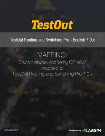
00e0 f923 a820 00a0 2471 e444 0800 4500 002c 9d08 4000 8006 8bff808f 8990 808f 4715 065b 0050 0009 465b 0000 0000 6002 2000598e 0000 0204 05b4Here, each byte is represented by two hexadecimal digits. The data shown does not contain thetrailer of the Ethernet frame. In Figure 0.12 we show how these bytes are mapped to theEthernet header, IP header, and TCP header.4 bytesdestination address00:e0:f9:23:a8:20Ethernetheader(14 bytes)source address0:a0:24:71:e4:44type0x0800version0x4IP Header(20 bytes)Type of e-to;iveprotocol0x800x06cource IP address128.143.137.144destination IP address128.143.71.21header lengthsource port number162710TCP Header(24 bytes)0x6Ethernettrailer(4 bytes)destination port number8010sequence number0x0009465backnowledgement number0x00000000flags0000102unused0000002TCP checksum0x598eoption typeoption length0x020x04header lengthtotal length (in bytes)0x002cfragment offset0000000000000 2header checksum0x8bffwindow size819210urgent pointer0x0000maximum segment size146010CRCFigure 0.12. Encapsulation of a frame (0xN indicates a hexadecimal representation, N10 indicates a decimal representation,and N2 indicates a binary representation of a number).We now parse the bytes of the frame, just like the protocol stack at a host would parse theframe. For orientation, we refer to Figure 0.12, which contains the final results of the processingof the frame. The first 14 bytes represent the fixed-sized Ethernet header:0.14
00e0 f923 a820 00a0 2471 e444 0800The first six bytes of the header contain the destination MAC address for this frame, and thenext six bytes contain the source MAC address. We can verify that these are the addresses ofRouter137 (00:e0:f9:23:a8:20) and Argon (00:a0:24:71:e4:44). The last twobytes of the Ethernet header contain the demultiplexing field. The value 0x08004 indicates thatthe payload of the frame following the Ethernet header is an IP datagram. Therefore, theEthernet device driver that receives the frame can pass the frame to IP for further processing.The next 20 bytes are the IP header and are as follows:4500 002c 9d08 4000 8006 8bff 808f 8990 808f 4715The first four bits are the version number of the Internet Protocol. The value 0x4 indicates thatthis datagram is formatted according to the IP version 4 (IPv4) specification. The next four bitsindicate the length of the IP header in multiples of four bytes. The value 0x5 states that thelength of the IP header is 5 x 4 20 bytes, which is the minimum size of an IP datagram. Thenext byte specifies the type of service requested by this IP datagram. The value 0x00 states thatthis frame does not have any specific service requirements. The next two bytes (0x002c)contain the length of the IP datagram. At this point, IP knows that the IP datagram is 4
1. A TCP/IP Networking Example Consider a web browser (a web client) at a host with name Argon.cerf.edu (“Argon”) that makes a web access to a web server on a host with name Neon.cerf.edu (“Neon”).1 The web access is illustrated in Figure 0.1. Both hosts a