Transcription
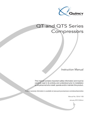
Slickline No conductorUpper Sheave Single strand wireStuffing BoxLubricatorTypical Wireline Rig-upLower SheaveWireline Unitswab valvemaster valveSprings3/14/2009George E. King EngineeringGEKEngineering.com1
3/14/2009George E. King EngineeringGEKEngineering.com2
3/14/2009George E. King EngineeringGEKEngineering.com3
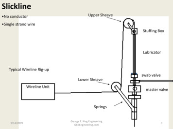
Wireline Surface Equipment Reels and ControlsBOPLubricatorsGrease (oil) Seals3/14/2009George E. King EngineeringGEKEngineering.com4
3/14/2009George E. King EngineeringGEKEngineering.com5
Wireline BOP3/14/2009George E. King EngineeringGEKEngineering.com6
Lubricator Layout and Loading – wireline operations3/14/2009George E. King EngineeringGEKEngineering.com7
Lubricator Length “Consider the tool string length whensizing the lubricator length. The availablelength to swallow a tool string is from thetop of the swab valve to the bottom of theflowtubes. This length should be theTOTAL tool length, line head to bottomnose, plus 3 extra feet.”3/14/2009George E. King EngineeringGEKEngineering.com8
Stuffing Box – the Main Seal on theWire Braided Line – Grease Injector Slick Line - Rubber elements with and withoutoil injection capacity. A hydraulic oil is usuallyused for sealing and lubrication of the wire.3/14/2009George E. King EngineeringGEKEngineering.com9
Schematic of a Grease Injector for Braided LineRubber ElementsFlow TubesGrease Injection3/14/2009George E. King EngineeringGEKEngineering.com10
Braided Line Grease Injector– Blowing grease in the air? - the rubber is worn out.– Loosing grease in the well? -flow tubes too big/worn,braided line worn. Either way, too much clearance.– Number of tubes depends on the pressure. Bottom flowtube must be close to diameter of braided line.– If grease use is high (over 10 lb/day) operator may bepumping too much grease - more than needed.– Greases comes in different viscosities, formulated forpressure and temperature combinations .– If hanging gauges in well on braided cable during a job,do not pump grease - just tighten rubbers.– Some greases thicken and/or emulsify with well orinjected fluids. Formation damage can be severe.3/14/2009George E. King EngineeringGEKEngineering.com11
Wireline Fishing/Jarring BestPractices Maximum fishing time of 45 minutes to 1 hourbefore reheading wire – move the fatiguepoint (fatigue caused by continual workingover the shieves during jarring) – usually cutoff 100 ft. Work to 50% of max load. Use of 0.125 and braided wire considered?3/14/2009George E. King EngineeringGEKEngineering.com12
3/14/2009George E. King EngineeringGEKEngineering.com13
Some Wire Types Bright Steel – most widely used, not for H2S orCO2 AISI 304 – H2S service AISI 316 - H2S service3/14/2009George E. King EngineeringGEKEngineering.com14
Wire Limits (Bright Steel)(estimates only)Wire SizeMinimum Tensile StrengthMaximumWork Level0.072”972 lb.500 to 600 lb. ?0.082”1239 lb.850 lb. ?0.092”1547 lb.1000 lb. ?0.108”24361400 lb. ?0.125”32001800 lb. ?Minimum tensile is 75% of rated break strength.Data for “bright plow steel wire”3/14/2009George E. King EngineeringGEKEngineering.com15
Wire Limits - AISI 304(estimates only)Wire SizeMinimum Tensile StrengthMaximumWork Level0.082”1280 lb.850 lb. ?0.092”1582 lb.1000 lb. ?0.105”2070 lb.1400 lb. ?Minimum tensile is 75% of rated break strength.3/14/2009George E. King EngineeringGEKEngineering.com16
Wireline breaks involve fatigue, physical damage to the wire, corrosion and other factors.3/14/2009George E. King EngineeringGEKEngineering.com17
Nominal Weight of WireWire Size0.0720.0820.0920.1080.1253/14/2009Wt per 1000 ft of wire14 lb18 lb22.6 lb31 lb44 lbGeorge E. King EngineeringGEKEngineering.com18
Selecting Wireline What devices have to be pulled (weights,loads)? What impact forces are needed? What are the tubing sizes?– Small tubing – smaller wire, easier to work andrecover. Corrosion potential? Local preferences?3/14/2009George E. King EngineeringGEKEngineering.com19
Braided line – stronger (2800 to 3500 lb working strength, but less “feel” whenfishing and slower line speed.Watch abrasion of steel by braided wire.Harder to get a seal in stuffing box/grease injector3/14/2009George E. King EngineeringGEKEngineering.com20
Wireline Operations Common workovers with wireline– liquid and fill tags– gauge running and retrieval– gas lift valve replacement– sleeve shifting– plug and packer setting– bailer runs3/14/2009George E. King EngineeringGEKEngineering.com21
Wireline Operations Advantages - speed, cost, footprint, “feel” Disadvantages– low wire strength– lack of rotation– lack of circulation Problems––––3/14/2009lack of experienced operatorpoorly maintained unitsimpatiencepoor well recordsGeorge E. King EngineeringGEKEngineering.com22
Common Problems with Wireline Wire breaks– Fatigue (work hardening failure)– corrosion (H2S, CO2, acids)– load failure Damage to well equipment and coatings fromwire abrasion3/14/2009George E. King EngineeringGEKEngineering.com23
Slick Line Torsion Tester - Twist testing has eliminated wire breakage in many areas.3/14/2009George E. King EngineeringGEKEngineering.com24
3/14/2009George E. King EngineeringGEKEngineering.com25
Wire Fatigue – Number of turns tobreak wire Wire Size– 0.072– 0.082– 0.092– 0.108– 0.1253/14/2009NewMin turns to break292623201822George E. King EngineeringGEKEngineering.com26
Look at the type of break Smooth – no problem Jagged – embrittlement possible, even if theturn count is within minimum tolerance, putnew wire on the unit.– Corrosion by H2S and CO2– Fatigue mixed with embrittlement3/14/2009George E. King EngineeringGEKEngineering.com27
Wireline Fatigue Limit the wireline crews to 50 - 60 jar cyclesprior to POOH and cut of /- 50m wire3/14/2009George E. King EngineeringGEKEngineering.com28
Some Very Basic Learnings About “90%” of success is in the operator selection. Wire line breaks can be almost totally eliminated bytorsion testing of wire and limiting jarring times. When wire breaks, always expect a little wire abovethe rope socket. When possible, run a fishing tool that has a release. H2S wells can be wireline nightmares3/14/2009George E. King EngineeringGEKEngineering.com29
Wireline Equipment Checks 1. Measure and record data for all equipmentthat goes in the hole.– diameters of every component– tool body lengths– thread patterns of each component– Tapers, shoulders, unusual equipment– compressed and extended jar lengths3/14/2009George E. King EngineeringGEKEngineering.com30
Wireline Equipment Checks 2. Wire history– size, material– use history– corrosion treatment– torsion testing (turns before breaking)– jarring time in one spot (working continuouslyover the shieve or pulley thins and fatigues wire)3/14/2009George E. King EngineeringGEKEngineering.com31
Wireline Equipment Checks 3. Equipment– working condition– support for loads– lubricator pressure limit– seal equipment capability and backup– seal equipment sizing3/14/2009George E. King EngineeringGEKEngineering.com32
0.125” Wireline extra pulling cap. advantage, w/stubborn SSSV's need 16" shieves and winch, tools etc., to match more muscle required to make the rope socket when fishing, it tends to come out in 2-10' lengths. consider use of sidewall cutters, box off wire if break main hurdle is education of the operators extra weight when deep cancels out extra pulling cap. less "feel", less accelaration when jarring3/14/2009George E. King EngineeringGEKEngineering.com33
Wireline Basic Equipment Rope SocketJarsToolsWireline torsion testers3/14/2009George E. King EngineeringGEKEngineering.com34
3/14/2009George E. King EngineeringGEKEngineering.com35
3/14/2009George E. King EngineeringGEKEngineering.com36
3/14/2009George E. King EngineeringGEKEngineering.com37
There are many different types of rope rockets.The number of turns in the wire influences breaking strength.If wire breaks prematurely during rope sock makeup , do a torsion test.3/14/2009George E. King EngineeringGEKEngineering.com38
3/14/2009George E. King EngineeringGEKEngineering.com39
Wire Cutter Problems in DeviatedWells When the tool string is stuck, the mostcommon approach is to cut the wire as closeto the BHA as possible with a drop-type cutter. In high angle wells there is potential for atraditional wire cutter not to get to bottom. Need for a releasable rope socket?3/14/2009George E. King EngineeringGEKEngineering.com40
Junk in the bottom of a well3/14/2009George E. King EngineeringGEKEngineering.com41
Jars Mechanical or spang jars – old design, butvery effective– Mostly for near vertical wells, but have been usedin deviated sections (losese effectiveness asdeviation increases) Hydraulic jars– Much slower acting– Less (?) affected by deviation – still requires a tightwire above the jar.3/14/2009George E. King EngineeringGEKEngineering.com42
3/14/2009George E. King EngineeringGEKEngineering.com43
Fishing neck must be in good shapewith sharp shoulders. Also, look forany damage to threads.3/14/2009George E. King EngineeringGEKEngineering.com44
Hydraulic Jars Hydraulic Jars – initial problems.- Problematic operation in gas & hot wells.- Minimal impact forces due to short stroke length. Spring Jars were developed with longer stroke leading togreater impact forces.- Fixed spring value - jar had to be disassembled to change.- Typically only 3 different values of spring available. Adjustable Upstroke Jar (PAJ) (Petroline- Weatherford) - Longer stroke leading to greater impact forces.- Jar setting can be changed across a wide range and without disassembly.- Disc spring stack design a highly efficient stored energy medium.3/14/2009George E. King EngineeringGEKEngineering.com45
Tools Basic Tool String Design Running Tools Fishing Tools3/14/2009George E. King EngineeringGEKEngineering.com46
Pulling Weight Into the Well – TheProblems Long lubricators required Rig up height increased Added friction in deviated wells from longerweight stem Less wireline load capacity3/14/2009George E. King EngineeringGEKEngineering.com47
3/14/2009George E. King EngineeringGEKEngineering.com48
3/14/2009George E. King EngineeringGEKEngineering.com49
Tools Stem Knuckles Various Tools3/14/2009George E. King EngineeringGEKEngineering.com50
3/14/2009George E. King EngineeringGEKEngineering.com51
3/14/2009George E. King EngineeringGEKEngineering.com52
3/14/2009George E. King EngineeringGEKEngineering.com53
Gauge ring cuttersProblems in highly deviated wells sticking3/14/2009George E. King EngineeringGEKEngineering.com54
Dimension should closely follow id of tube - this allows checkfor partial collapse and prevents material from getting on topof tool string.3/14/2009CamcoGeorge E. King EngineeringGEKEngineering.com55
CT Fishing Survey ToolsTools and devices which help determine fish type andorientationLead impression blocks:Provide information on profile and orientation of the fishExperience required to interpret recovered impressionDownhole cameras transmit images/video to surface:Clean wellbore fluid requiredTemperature/time limitationsHigh cost of service3/14/2009George E. King EngineeringGEKEngineering.com56
Set down once and retrieve. Multiple set downs onlyconfuse the imprint.Also known as a “confusion block” - generally for goodreason.3/14/2009George E. King EngineeringGEKEngineering.com57
3/14/2009George E. King EngineeringGEKEngineering.com58
Lead Impression BlockInterpretationOffset andincompleteimpressionFish lying on sideof wellbore3/14/2009George E. King EngineeringGEKEngineering.com59
3/14/2009George E. King EngineeringGEKEngineering.com60
Some lead impression blocks may be made in various shapes for assistance in describing shapesor locations of fish.3/14/2009George E. King EngineeringGEKEngineering.com61
Impression Block Best Practices Run a near drift block Set down one time and POOH Keep a file of paper cut-outs of pipe bodydiameters, connection diameters, toolconnections, etc., that might look up. Helps tomatch the cut-out to the shape of theimpression.3/14/2009George E. King EngineeringGEKEngineering.com62
Downhole video much better thanimpression blocks for realinformation3/14/2009George E. King EngineeringGEKEngineering.com63
3/14/2009George E. King EngineeringGEKEngineering.com64
One type of running tool3/14/2009George E. King EngineeringGEKEngineering.com65
3/14/2009George E. King EngineeringGEKEngineering.com66
JD Pulling Tools – note sharp shoulders andclean tool bodies3/14/2009George E. King EngineeringGEKEngineering.com67
JD Pulling tool – commonly run just belowthe jar in the BHA.JD tools are used for external fishing necks.3/14/2009George E. King EngineeringGEKEngineering.com68
The tops of fishing necks areusually tapered to assist thefishing tool in locating andattaching.Note sharp shouldersNote the extended body of theneck – this allows someextension above the top ofdebris that may settle on top ofthe plug.3/14/2009George E. King EngineeringGEKEngineering.com69
Outside fishing neck with flow throughcapacity.3/14/2009George E. King EngineeringGEKEngineering.com70
One problem with inside fishing necksis that debris may prevent the prongfrom entering and latching.3/14/2009George E. King EngineeringGEKEngineering.com71
Inside fishing neck for a GS running tool3/14/2009George E. King EngineeringGEKEngineering.com72
Fish Type and Dimensions Many fishing tools only catch on limited size range(OD or ID) When dimensions of fish are known:– Prepare accurate fishing diagram– Prepare wellbore or completion diagram Factors influencing selection of tools/techniques:– Fish stuck/free– Fill or junk on top of fish– Fish material properties e.g. small ferrous objects retrieved by magnetic devices3/14/2009George E. King EngineeringGEKEngineering.com73
Fishing Diagram - Fishing NeckDetail3.750 in.2.313 in.2.000 in.1.813 in.Depth to top of fish3455.50 ft2.000 in. 1.500 in.3.500 in.4.250 in.Fish OD and length informationare presented in a generalfishing diagram3/14/2009Wellbore tubularGeorge E. King EngineeringGEKEngineering.com74
3/14/2009George E. King EngineeringGEKEngineering.com75
The top of a gas liftvalve, bent over in thewellbore.DHV Inc.3/14/2009George E. King EngineeringGEKEngineering.com76
Wellbore and CompletionGeometry Minimum tubular or restriction size– Determines maximum OD of CT/toolstring which can be used When assessing drift clearances– Consider removal of fill Pressure differential may exist across the fish– Can force toolstring up or down wellbore When determining overpull available at fish– Consider wellbore geometry3/14/2009George E. King EngineeringGEKEngineering.com77
3/14/2009George E. King EngineeringGEKEngineering.com78
Bailer BottomFlapper in the bottom of the bailertube.3/14/2009George E. King EngineeringGEKEngineering.com79
Tools for running and retrieving gas lift valves – note:maximum length of tools and valve or dummy must fit into thetool body. Latching too long a valve can stick assembly.Detent finger on tool body – indexes tool and orients forrunning and retrieval.3/14/2009George E. King EngineeringGEKEngineering.com80
Tubing End Locator - Problem “Upon RIH with the tool, we encountered high pick-upweights and were unable to enter the liner and the 7" sectionwhere the finger should open up. In this scenario we beganto POOH with the pin unsheared. Since the spring was forcingthe finger out, it would act as a hook on anynipples/restrictions encountered while pulling out of hole.However, because of the smaller ID, the finger would beunable to push out more than approx 45 degrees and hencethe shear pin would never see any force - the pivot pin wouldsee all the stress.”3/14/2009George E. King EngineeringGEKEngineering.com81
End of Tubing Locator. Arm is springloaded and tucked into the tubingwith end pointing upward. At end oftubing, the arm is deployed by thespring. It cannot swing into the slot inthe body until it shears the pin.It is normal to pin with a small pin,perhaps even steel – but watch theprofiles and unusual diameterchanges.3/14/2009George E. King EngineeringGEKEngineering.com82
High Angle Wells Rollers– Used for getting wireline assemblies into deviatedwells.– Most needed for heavy tool strings– Can increase application of wireline into wells toover 80 degrees. Friction Reduction– Chemical additives reduce friction by 30%3/14/2009George E. King EngineeringGEKEngineering.com83
Roller stem used in higher deviation wells. Watch problems with deposits suchas scale, paraffins, and asphatenes.3/14/2009George E. King EngineeringGEKEngineering.com84
3/14/2009George E. King EngineeringGEKEngineering.com85
Wireline Checklist – a few pointers1.2.3.4.5.6.7.Check pipe connection connection and pressure rating of lubricator andBOPCheck mandrel profiles and other tools to be run for correct OD, profiletype and function.Check pressure equalization features on all pulling and retrieving toolsCheck that running, pulling and fishing tools have the correct latchmechanism for the tool being run or retrieved.Check wireline unit for proper function (engine, clutch and line)Check wire with twist test for fatigueHave emergency plan for handling breaks and leaks.3/14/2009George E. King EngineeringGEKEngineering.com86
Wireline Equipment Checks 1. Measure and record data for all equipment that goes in the hole. - diameters of every component - tool body lengths - thread patterns of each component - Tapers, shoulders, unusual equipment - compressed and extended jar lengths 3/14/2009 30 George E. King Engineering GEKEngineering.com