Transcription
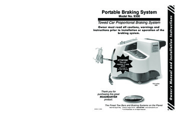
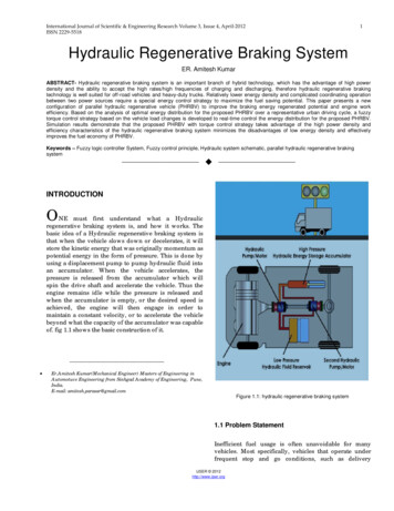
International Journal of Scientific & Engineering Research Volume 3, Issue 4, April-2012ISSN 2229-55181Hydraulic Regenerative Braking SystemER. Amitesh KumarABSTRACT- Hydraulic regenerative braking system is an important branch of hybrid technology, which has the advantage of high powerdensity and the ability to accept the high rates/high frequencies of charging and discharging, therefore hydraulic regenerative brakingtechnology is well suited for off-road vehicles and heavy-duty trucks. Relatively lower energy density and complicated coordinating operationbetween two power sources require a special energy control strategy to maximize the fuel saving potential. This paper presents a newconfiguration of parallel hydraulic regenerative vehicle (PHRBV) to improve the braking energy regenerated potential and engine workefficiency. Based on the analysis of optimal energy distribution for the proposed PHRBV over a representative urban driving cycle, a fuzzytorque control strategy based on the vehicle load changes is developed to real-time control the energy distribution for the proposed PHRBV.Simulation results demonstrate that the proposed PHRBV with torque control strategy takes advantage of the high power density andefficiency characteristics of the hydraulic regenerative braking system minimizes the disadvantages of low energy density and effectivelyimproves the fuel economy of PHRBV.Keywords – Fuzzy logic controller System, Fuzzy control principle, Hydraulic system schematic, parallel hydraulic regenerative brakingsystem—————————— ——————————INTRODUCTIONONE must first understand what a Hydraulicregenerative braking system is, and how it works. Thebasic idea of a Hydraulic regenerative braking system isthat when the vehicle slows down or decelerates, it willstore the kinetic energy that was originally momentum aspotential energy in the form of pressure. This is done byusing a displacement pump to pump hydraulic fluid intoan accumulator. When the vehicle accelerates, thepressure is released from the accumulator which willspin the drive shaft and accelerate the vehicle. Thus theengine remains idle while the pressure is released andwhen the accumulator is empty, or the desired speed isachieved, the engine will then engage in order tomaintain a constant velocity, or to accelerate the vehiclebeyond what the capacity of the accumulator was capableof. fig 1.1 shows the basic construction of it. Er.Amitesh Kumar(Mechanical Engineer) Masters of Engineering inAutomotuve Engineering from Sinhgad Academy of Engineering, Pune,India.E-mail: amitesh.parasar@gmail.comFigure 1.1: hydraulic regenerative braking system1.1 Problem StatementInefficient fuel usage is often unavoidable for manyvehicles. Most specifically, vehicles that operate underfrequent stop and go conditions, such as deliveryIJSER 2012http://www.ijser.org
International Journal of Scientific & Engineering Research Volume 3, Issue 4, April-2012ISSN 2229-5518vehicles, are most affected by these inefficiencies. Withincreasing fuel prices and inefficient fuel use, there is anobvious need for a more resourceful solution. Thesolution is Hydraulic regenerative braking system.1.2 ObjectivesThe primary objective of this topic is to validate that aHydraulic regenerative braking system can increase thestop and go fuel efficiency of a vehicle by 32%.2design aspect of the hydraulic regenerative brakingsystem.2.2 Hybrid Background2.2.1 Types of HybridsHybrid vehicles are becoming more and more common inthe auto industry. A hybrid vehicle is simply a vehiclethat operates using a primary engine and secondaryenergy storage device. While electric hybrid vehicles arethe most familiar and have been commercially produced,Hydraulic regenerative braking system technology isbeing investigated as a better hybrid option. Hydraulicregenerative braking vehicles are being introduced intothe industry by companies such as Parker HannifinCorporation and Eaton Corporation. Hydraulicregenerative braking system can be divided into twodifferent system types: parallel and series.In a parallel hydraulic hybrid, the hydraulic componentsare connected to the conventional transmission anddriveshaft. While the engine is always running andconsuming fuel, the hydraulic system is able to assist inacceleration when the engine is working its hardest, thusincreasing fuel efficiency. Series hydraulic hybridsystems use the same basic principles as parallel systems,but do not utilize the conventional transmission ordriveshaft. The hydraulic system transmits all powerdirectly to the wheels.Figure 1.2: Efficiencies while braking/ accelerating2.2.2 Benefits of Hydraulic Breaking System2. DESIGN FUNCTIONALITYThe design is transparent so that the control of thissystem functions as intuitively as possible. It wasdesigned to be controlled by gas and brake pedals so thatany new user will be familiar with its control. The designof the hydraulic system was created so it in no wayhinders the performance or integrity of the vehicle. Notonly will the system be predictable in use, it will bereliable and consistent.2.1 Scope of the topicThe scope of the topic was to test hydraulic regenerativebraking technology, rather than designing a marketablesystem. Much of the time was spent on betterunderstanding and implementing the knowledge and2.2.2.1 Less Energy ConversionsA hydraulic hybrid offers a number of advantages overelectric hybrids. The largest of these advantages is thatthe system employs less energy conversions, leading tohigher efficiencies. An electric hybrid converts kineticenergy to electrical energy and then to chemical energythat is stored in a battery. A hydraulic hybrid convertskinetic energy to fluid pressure energy and this is howthe energy is stored. This results in one less energy formconversion to help the hydraulic regenerative brakingsystem achieve higher efficiency than other types ofhybrids.IJSER 2012http://www.ijser.org
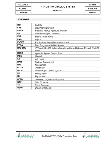
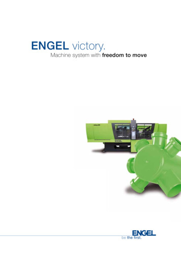
International Journal of Scientific & Engineering Research Volume 3, Issue 4, April-2012ISSN 2229-551832.2.2.2 Regenerative BrakingHydraulic Regenerative braking is a large advantage to ahybrid system, especially when the vehicle is subject tofrequent stops. Normally, in a conventional vehicle, all ofthe kinetic energy is lost to heat, an irreversible process.A hybrid however captures some of this energy throughregenerative braking to be reused the next time thevehicle accelerates. Through simulations, it wasestimated that 70% of the kinetic energy of the vehiclewould be recycled through a regenerative braking eventwith the hydraulic regenerative braking system.2.2.2.3 Optimal Engine SpeedOperating the engine of a hydraulic regenerative brakingvehicle at its optimal operating point is of value becausethe engine can generate the most power per flow rate offuel. To find this point for the engine used in this project,the following data was obtained from the manufacturer:engine power versus engine speed, engine torque versusengine speed, and engine fuel consumption rate versusengine speed. These data graphs are presented below inFigure 2.1, Figure 2.2, and Figure 2.3. The engine used inthis project is represented by the orange line in all threefigures. From this, a ratio was calculated at each enginespeed of engine power or torque per volumetric flow rateof fuel. This was then graphed to find the optimumoperation point. From Figure 2.4 and Figure 2.5, it wasdetermined that the slower the engine runs, the better thetorque per fuel consumption rate. However, the powergraph shows a speed at which the engine maximized theamount of power obtained per fuel flow rate. From thisdata, the engine would be tuned to run at about 2200 rpmwhen pumping hydraulic fluid. This speed is close to theoptimal operating speed for our engine, thus providingthe best use of the fuel consumed by the engine.Figure 2.1: Engine power dataFigure 2.2: Engine torque dataIJSER 2012http://www.ijser.org
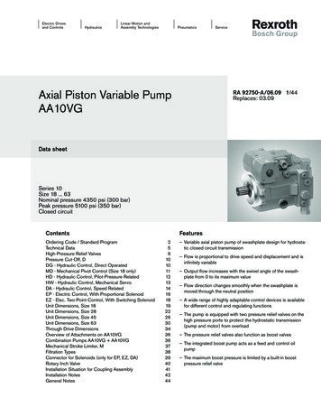
International Journal of Scientific & Engineering Research Volume 3, Issue 4, April-2012ISSN 2229-55184Figure 2.5: Graph of power per fuel flow rate versus engine speedFigure 2.3: Engine fuel consumption dataFigure 2.4: Graph of torque per fuel flow rate versus engine2.3 Hydraulic regenerative braking systemA Hydraulic regenerative braking system schematic wascreated for a series hydraulic hybrid vehicle. Thisschematic was designed to include acceleration andbraking control using hydraulic flow control valves,regenerative braking using check valves, and forewordsand reverse directions using a directional selector valve.An important safety feature of the hydraulic schematic isthe high pressure relief valve, which ensures that thepressure in the system never reaches an unsafe level. Acopy of this schematic can be found in Figure 2.6speedIJSER 2012http://www.ijser.org
International Journal of Scientific & Engineering Research Volume 3, Issue 4, April-2012ISSN 2229-55185meantime, adjust the engine working point onto theoptimal fuel consumption region. When the hydraulicaccumulator pressure reaches the highest initiativecharging pressure value, the vehicle is driven by thehydraulic accumulator and hydraulic pump/motor. Theintroduction of hydraulic pump minimizes the lowerenergy density disadvantage of the accumulator andmakes the engine work in high efficiency region throughthe initiative charging function.3.1. Impact of pump/motor install positionon braking energy regenerationAllocate the hydraulic pump/motor behind the frontdifferential (the front-wheel-drive model) has a greaterpotential in braking energy regeneration because of theincreasing of the front axle load during braking. The frontwheel braking force Ff1 and the rear wheel braking forceFf2 are given by [Eq. (1) and (2)], respectively.Fig. 2.6 New configuration of parallel hydraulic regenerative brakingsystem.Fig.2.6 presents a new type of configuration for hydraulicregenerative braking system which consists primarily ofan engine, a high-pressure accumulator, a low pressurereservoir, a variable displacement hydraulic pump, and avariable displacement hydraulic pump/motor unit,clutch, transmission and differential. The hydraulicpump/motor and hydraulic pump are coupled to thepropeller shaft via a planetary gear system. Duringdeceleration, the hydraulic pump/motor decelerates thevehicle while operating as a pump to capture the energynormally lost to friction brakes in a conventional vehicle.Also, when the vehicle brake is applied, the hydraulicpump/motor uses the braking energy to charge thehydraulic fluid from a low pressure hydraulicaccumulator into a high-pressure accumulator, increasingthe pressure of the nitrogen gas in the high-pressureaccumulator. The high pressure hydraulic fluid is usedby the hydraulic pump/motor unit to generate torqueduring the next vehicle acceleration. It is designed andsized to capture braking energy from normal, moderatebraking events and is supplemented by friction brakes foraggressive braking. Cruise conditions, the hydraulicpump works for charging the hydraulic accumulator,where u is the friction coefficient between tire and roadsurface, is the distance from vehicle center of gravity tofront axle center line, is the distance from vehicle centerof gravity to rear axle center line, is the wheel base andis the height of the center of gravity. During thecourse of braking, the front axle load increases and therear axle load decreases, therefore, install pump/motorbehind the front differential has greater potential inbraking energy regeneration. The regenerative brakingtorque distributions under different pump/motor installposition are shown in Figs. 3.1 and 3.2 the impact ofhydraulic pump/motor install position on brakingenergy regeneration under different driving cycles isshown in Fig.3.33.2. Operating conditions of PHRBVParallel hydraulic hybrid vehicle mainly includes erating/climbing condition and regenerativebraking condition.3.2.1. Hydraulic drive conditionIJSER 2012http://www.ijser.org
International Journal of Scientific & Engineering Research Volume 3, Issue 4, April-2012ISSN 2229-55186When vehicle starts and the pressure of hydraulicaccumulator is higher than the minimum workingpressure value, the commanded power of vehicle issupplied only by hydraulic pump/motor. When thepressure in hydraulic accumulator declines to theminimum working pressure value, the vehicle isswitched to cruise condition.Fig. 3.1. Regenerative braking torque distribution of front-wheeldrive model.Fig. 3.3 Impact of hydraulic pump/motor configuration on brakingenergy regeneration.3.2.2. Low-speed cruise conditionDuring the course of low-speed cruise condition, majoroutput power of the engine is used for driving vehicle,the others power is used for charging the hydraulicaccumulator, meantime, adjusts the engine load. Thetorque relationship is shown as [Eq. (3)]where ,andare the torque of differential, theengine output torque and hydraulic pump chargingtorque, respectively,is the velocity ratio oftransmission,is the velocity ratio of hydraulic pump tothe propeller shaft,is the efficiency of hydraulicpump to the propeller shaft, ,are the efficiency ofengine and the efficiency of transmission and , is thetorque loss due to friction and churning loss for thetransmissions to differential.Fig. 3.2 Regenerative braking torque distribution of rear wheel drive.3.2.3. Middle and high-speed cruise conditionIJSER 2012http://www.ijser.org
International Journal of Scientific & Engineering Research Volume 3, Issue 4, April-2012ISSN 2229-5518During the course of middle-speed and high-speed cruisecourse, in order to enable the engine work at a relativelymiddle speed region, the hydraulic pump/motor supplyauxiliary power, the hydraulic pump offers hydraulic oilfor the pump/motor or charging hydraulic accumulator.The torque relationship is shown as [Eq. (4)],74. OPTIMIZATION VIA DYNAMICPROGRAMMINGDynamic programming is a powerful tool to solvegeneral dynamic optimization problems. In this study,the objective is to search for the optimal trajectories ofcontrol signals, including the engine command, hydraulicpump command and hydraulic pump/motor commandto minimize the fuel consumption of the PHRBV over thewhole driving cycle. i.e.[Eq.(8)]Where/ is the torque of hydraulic pump/motor,/ is the velocity ratio of hydraulic pump/motor tothe propeller shaft and/is the efficiency ofhydraulic pump/motor to the propeller shaft.3.2.4. Accelerating/climbing conditionIn order to enable the engine runs in a certain region or asmooth rise, the hydraulic pump does not work and thehydraulic pump/motor providesis shown as follows: the auxiliary power. The torquerelationship. [Eq.(5)]where L is the fuel consumption over a time segment, Nis the driving cycle length and x, u are the vectors of statevariables and control signals respectively.The objective function contains three components:(1) The engine fuel consumption. This term onlyrepresents the fuel consumption assuming the engine isrotating in a steady state. [Eq.(9)]3.2.5. Regenerative braking conditionDuring braking, the hydraulic pump/motor works atpump condition, uses the braking energy to charge thehydraulic fluid from a low pressure hydraulicaccumulator into a high-pressure accumulator, increasingthe pressure of the nitrogen gas in the high-pressureaccumulator. The regenerative braking force of hydraulicpump/motor is as follows: [Eq.(6)](2) The second term is used to compensate the extra fuelconsumption for the frequent start/stop engine andshifting gears. [Eq.(10) and (11)](6)whereis the final ratio of differential. It is designedand sized to capture braking energy from normal,moderate braking events and is supplemented by frictionbrakes and engine anti-trailer brakes for aggressivebraking. The anti-trailer braking force of engine isdetermined by [Eq. (7)]Frequent start/stop engine and shifting gears worsen fuelconsumption and affect the ride comfortableness.(3) In order to match the final value of accumulator SOCwith its initial value, a penalty term is added. [Eq.(12)](7)whereis the engine moment of inertia and z is theseverity of braking.Where α α, β, γ are the weight coefficients.Fig.4.1 presents the optimal trajectories of operatingpoints of the engine and the vehicle operating modesover the NYCC duty cycle.The accumulator pressure is characterized by largefluctuations due to high power flows through the system.IJSER 2012http://www.ijser.org
International Journal of Scientific & Engineering Research Volume 3, Issue 4, April-2012ISSN 2229-5518Large negative swings hydraulic pump/motor powerindicate the effective capturing of braking energy. Sincethe Dynamic Programming algorithm is forward-looking,the resulting optimal control signals are not applicable inpractice. By analyzing the DP results, the useful hints forderiving improved strategies can be practicallyimplemented.Clearly, at the beginning of each vehicle launch, thehydraulic pump/motor provides total propulsion powerto avoid forcing the engine to work in the lowspeed/load region. With the exception of launch, theengine and pump/motor is used exclusively, becauseengine and hydraulic pump/motor have thecharacteristics of higher efficiencies at higher loads.Whenever the required power exceeds the maximumpower provided by the pump/motor, the engineexclusive working mode is switched. In the meantime,the hydraulic pump is used to adjust engine workingload through initiative charging pressure function andkeep propulsion component at high load/high efficiencyregion. During the cruise speed stage, the pump/ motoris used to satisfy the total power demand whenever thereis energy available in the accumulator, in the meantime,the frequent dynamical transitions between the variousoperation modes is needed to avoid.8the fuel economy potential fullest. In the paper, thevehicle load is introduced as an input of the fuzzy logiccontroller through a sense proportion valve to determinethe load condition of the vehicle. Appropriately reducethe pump charging torque and maximum chargingpressure value when the load is small. Otherwise, enlargethe pump charging torque and maximum chargingpressure value.The three inputs of the fuzzy logic controller are thedifference between the optimal torque (corresponding tothe current engine rotation speed) and the vehiclerequired torque, the pressure (SOC) of the accumulatorand the vehicle load. The difference between optimaltorque and requirement torque (DT) is divided into fivefuzzy subsets: {PL, PS, ZERO, NS, NL}. Similarly, theaccumulator’s SOC is divided into three fuzzy subsets:{HIGH, MED, LOW}, and the vehicle load is divided intothree fuzzy subsets: {HIGH, MED, LOW}. The twooutputs of the fuzzy logic controller are hydraulicpump/motor’s output torque and the hydraulic ump’sinitiative charging pressure torque, while the fuzzysubsets are {LARGE, MED, SMALL, ZERO} and {LARGE,SMALL, ZERO}, respectively. Figs.5.1 and 5.2 present theinput membership functions and the fuzzy logic blockdiagram.Table 1 presents a list of if – then rules that represent thetorque control strategy based on the analysis of DPoptimization results.Fig. 4.1 Dynamic Programming results obtained over NYCC drivingcycle.5. FUZZY TORQUE CONTROL STRATEGYFuzzy torque control strategy uses fuzzy logic to build anenergy distribution controller based on the useful hintsderived from optimization results. The vehicle load ofPHRBV varies in a wide range, if ignoring the change ofvehicle load, the energy control strategy cannot realizeFig. 5.1 Simplified block diagram of the fuzzy logic controller.IJSER 2012http://www.ijser.org
International Journal of Scientific & Engineering Research Volume 3, Issue 4, April-2012ISSN 2229-55189 Z, TP LThe main principle of the fuzzy torque control rules areas follows: (1) DT is equal to zero, which shows that theengine is located in the highest efficiency region andworking point need not to be adjusted; (2) DT is PL,which shows that the engine’s efficiency is very low andit should be shut off to make the accumulator providingdrive torque alone; (3) DT is PS, which shows that theengine is located in low efficiency region and initiativecharging pressure function of hydraulic pump is used toadjust working point into the optimal region; (4) whenDT is NL, it should meet the requirement of drivingtorque instead of economy; (5) when DT is NS,accumulator will help to reduce load.6. SIMULATION RESEARCHIn order to check the validity of the fuzzy torque controlstrategy based on PHRBV, the PHRBV simulation modelis implemented in SIMULINK. The simulationparameters of main components are listed in Table 2 andthe vehicle configuration is shown in Fig. l.Traditional power-split strategy, optimal powermanagement strategy and fuzzy torque control strategyare used to compare the improvement of fuel economy.The simulation results are shown in Figs. 6.1–6.3Fig. 5.2 Input membership functions for the scaled DT,SOC and Load.TABLE 1FUZZY CONTROL PRINCIPLE OFTORQUE CONTROL STRATEGYConditionsConclusionsIf DT NL & P LThen TP/M L, TP ZIf DT NS & P HThen TP/M L, TP ZIf DT NS & P MThen TP/M S, TP ZIf DT ZThen TP/M Z, TP ZIf DT PL & P ffi LThen TP/M L, TP ZIf DT PS & P HThen TP/M L, TP ZIf DT PS & P M & load LThen TP/M Z, TP SIf DT PS & P M & load MThen TP/M Z, TP SIf DT PS & P M & load HThen TP/M Z, TP LIf DT PS & P LThen TP/MTABLE 2PARAMETERS OF THE VEHICLE ANDMAIN COMPONENTVehicleWheel diameterRolling resistanceAerodynamic coefficientFrontal areaTotal vehicle mass0.50.020.656.5 214,310Accumulator systemVolumeMax working pressureMin working pressure63 L3218TransmissionGear ratioMain gear ratio6.62, 3.99, 2.47, 1.55, 14.85IJSER 2012http://www.ijser.org
International Journal of Scientific & Engineering Research Volume 3, Issue 4, April-2012ISSN 2229-5518Hydraulic pump/motorType and displacementMax torqueA4VG125795Hydraulic pumpDisplacement6010Fig. 6.2 Simulation results of optimal power management strategy.Fig. 6.3 Simulation results of fuzzy torque control strategy.Fig. 6.1 Simulation results of power-split strategyFigs. 6.1–6.3 show the differences between the powersplit strategy, optimal power management strategy andfuzzy torque management strategy. Hybridizationsignificantly improves vehicle’s fuel economy over thecity driving schedule. Hydraulic hybrid technology hasunique characteristics of high power density compared totheir electric counterparts, which enables regeneratingand reusing significant amounts of braking energy. Thelarge fluctuations of accumulator pressure demonstratedthe effective regeneration and reuse of braking energy.Even using engine universal performance characteristicsmap to design control strategies (power-split strategy),the fuel economy improved 15.6% compared to theconventional vehicle. However, power-split strategydesigned the energy distribution strategy only based onthe static engine universal performance characteristicsmap and ignored the hydraulic hybrid propulsion systemcharacteristics. Consequently, the energy distributionbetween primary and assistance sources is unreasonable.The regenerative braking ended earlier because theaccumulator is fully charged. In addition, the frequentswitching between engine mode and pump/motor modeworsens fuel consumption and ride comfortableness.Optimal power management strategy proposed by usedpump/motor to satisfy the total power demand,whenever there is energy available in the accumulator. Ifthe power requirement is more than what pump/motorcan provide, the engine will supplement the motorpower. But the power management strategy ignored therelatively lower efficiency of engine when the propulsionIJSER 2012http://www.ijser.org
International Journal of Scientific & Engineering Research Volume 3, Issue 4, April-2012ISSN 2229-551811is switched to engine work mode at the high speed of thevehicle, so that the fuel economy potential can’t berealized to its fullest.Fuzzy logic controller is used to reasonably distribute thepropulsion torque among the engine, hydraulic pumpand hydraulic pump/motor. Hydraulic pump/motor isused to satisfy the total power demand, whenever thereis energy available in the accumulator. The hydraulicpump is introduced to minimize the lower energydensity disadvantages of hydraulic accumulator andmove the engine working points into the highestefficiency region through initiative charging function.Hence, they enable a very dramatic increase of PHRBVsability to realize its fuel saving potential. Implementationof fuzzy torque control strategy improved fuel economyto 32%.Operating points of the engine controlled by power-splitstrategy were clustered in the mid/low load region(Fig.6.4). The fuzzy torque control strategy is able tomove most points into the mid/high load zonecharacterized by highest efficiencies (Fig.6.5). In addition,frequent use of the motor for vehicle acceleration oftendepletes the energy in the accumulator, which preparesthe system for the next regeneration event.Fig.6.5 Operating points of engine under fuzzy torque controlstrategy.The impacts of load changing on the PHHV fuel economyare compared in Fig.6.6 Under 1015, ECE EUDC, UDDSand HWFET driving cycles, the parallel hydraulic hybridvehicle with considering the changes of load has higherfuel economy, which demonstrated the effectively of thefuzzy torque control strategy.Fig. 6.6 Impacts of load changing on PHHV fuel economyFig. 6.4 Operating points of engine under power-split strategy.IJSER 2012http://www.ijser.org
International Journal of Scientific & Engineering Research Volume 3, Issue 4, April-2012ISSN 2229-551812minimized the disadvantage of accumulator’s lowerenergy density, which provided a practical feasiblemethod for improving fuel economy of the hydraulichybrid vehicle.REFERENCE[1] Wei YJ. Study on a new type of hydraulic hybrid sport utilityvehicle.Chaina Mech Engg 2006;17(15):1645-8(in Chinese)[2] Peng D,Yin CL,Zhang JW.Advanced braking control system for hybridelectric vehicle usingfuzzy control logic.SAE paper No.2006-01-3583[3] Paul M, jacek S. Development and simulation of a hydraulic hybridpowertain for use incommercial heavy vehicle. SAE Paper No.2003-01-3370.[4] Hewko LO, Weber TR. Hydraulic energy storage based hybridpropulsion system for a terrestrial vehicle .Energy Convers Engg Conf1990:99-105[5] Wu P,Luo N, Fronczak FJ, Beachle NH. Fuel economy and operatingcharacteristics of a hydropneumatic energy storage auto-mobile.SAEpaper851678[6] Wu B, Linmanagement for aFig. 6.7 Hydraulic system schematicCC,Filipi Z, PengH, Assanis D. Optimal powerhydraulic hybrid delivery truck. Vehicle syst Dyn2004:23-40.[7] Lin CC,Peng P, jessy W. power management strategy for a parallelA simplified hydraulic system schematic is shown inFigure 6.7 for the three major driving scenarios:accelerating, braking, and coasting. The diagrams tracethe fluids route through the system during each of thescenarios.hybrid electric truck. IEEE Trans control Syst Technol 2003(6):839-49.[8] Kim YJ,Filipi Z. Series hybrid propulsion for alight truck-optimization the thermostatic power management. SAE peper No.2007-240080.[9] Robyn AJ, Paul S, Steven B. Physical system model of a hybrid energystorage device for hybrid powertrain applications.SAE paper No.7. CONCLUSION2005-01- 0810[10] Hiroki S,Shigeru I, Eitaro K. Study on hybrid vehicle using constantHydraulic hybrid technology has the advantage of highpower density and the ability to accept the highrates/high frequencies of charging and discharging,therefore it is well suited for off-road vehicles and heavyduty trucks. But the lower energy density requires aspecial energy control strategy for PHRBV. In this study,a new type of configuration for PHRBV is presented. Afuzzy-based torque control strategy is built using theoptimization results according to the torque distributionamong the engine, hydraulic pump/motor and hydraulicpump, and the vehicle load changes is introduced to thefuzzy torque control strategy for realizing the fueleconomy fullest. The simulation results show that thenew configuration of PHRBV effectively improved thebraking regenerative potential. The fuzzy torque controlstrategy reasonably distributed the propulsion energybetween the power sources, improved the fuel economyand adaptability of different working conditions, andpressure hydraulicNo. 2004-01-3064.IJSER 2012http://www.ijser.orgsystem with flywheel for energy storage. SAE paper
of the hydraulic system was created so it in no way hinders the performance or integrity of the vehicle. Not only will the system be predictable in use, it will be reliable and consistent. 2.1 Scope of the topic The scope of the topic was to test hydraulic regenerative braking technology, ra