Transcription
Sanjivani Education Society’sSanjivani KBP Polytechnic, KopargaonCourse Code – CM-4-G Subject – CHM (17428) Subject Teacher –Prof. Y. S. ModheTopic-2- Storage Devices & InterfacingRecording Techniques: FM, MFM , RLL, perpendicular recordingDescribe Modified Frequency Modulation (MFM) and Run Length limited (RLL)techniques of recording with suitable example.(For MFM explanation 2 marks, Waveform or coding 2 marks) (For RLL explanation 2marks, Waveform or coding 2 marks)Three most common encoding methods are:1. FM encoding method2. MFM encoding method3. RLL encoding method1. FM Encoding Scheme: FM or Frequency Modulation was the original data-encoding scheme used for storing thedata on the magnetic recording surface. This method of data encoding is also known as the “Single density recording”. In this method, a clock signal is put with every data signal on the recording surface. Thisclock signal is used for synchronizing the read operation, as there will always be a clocksignal, whether the data signal is there or not. In this FM method of data recording a 1 bit is stored as two pulses(one clock pulse andone data pulse), and a o bit is stored as a one pulse and one gap or no pulse. For example, a binary number 1011 will be stored as PP PN PP PP1 Page
2. MFM Encoding Scheme: More data can be stored on the same surface or the data storage density can be increased,if the number of pulses required to store the data can be minimized.When minimizing the pulses, one should be careful that the number of no pulses togethershould not be very long; otherwise the disk controller may go out of synchronization withthe data.The MFM (modified frequency modulation) method of data storage, by reducing thenumber of pulses, is able to store more data without any data and synchronization numberof pulses, is able to store more data without any data and synchronization loss. In MFMrecording the 0s and 1s are encoded as given below1 is always stored as no pulse, and a pulse(NP) 0, when preceded by another 0, is stored as a pulse, and no pulse(PN) 0, when preceded by a 1, is stored as two no pulses(NN) If you store 1001 on the disk surface using the MFM storage method, it would be storedas NP NN PN NP. 3. RLL Encoding Scheme The RLL is encoding or the run length limited encoding is the most common encodingscheme used in the hard disk storage.This encoding scheme can be more accurately called as 2,7 RLL encoding because in thisscheme in a series or in a running length the minimum number of 0s next to each other istwo, and the maximum number of 0s together can not be more than seven.The RLL encoding scheme can store 50 percent more information than MFM encodingscheme on a given surface and it can store three times as much information as the FMencoding scheme. The Run length Limited name comes from the minimum number (runLength) and maximum number (run Limit) of “no pulse” values allowed between twopulses.2 Page
For the RLL encoding, an encoder/decoder (Endec) table is used to find the pulse signalto be used for different data bit groups. Endec table used by the IBM to convert bitinformation to the pulse signal is shown belowData BitPulse 0NNPNNPNN0011NNNNPNNNFor example, if you want to encode a byte 100011 to proper RLL pulse signal then the Bit 10 can be encoded as NPNN Bit 0011can be encoded as NNNNPNNN4. Perpendicular Encoding Virtually all hard drives record data using longitudinal recording which stores magneticbits horizontally across the surface of the media.However perpendicular recording which aligns magnetic signals vertically on the mediasurface has the potential to achieve higher data intensities because vertically orientedmagnetic bits use less space than longitudinally stored bits.Hard Disk Construction3 Page
A hard disk drive is made up of several physical components1)2)3)4)5)6)7)8)Disk plattersRead/write headsHead actuator mechanismSpindle motorLogic boardCables and connectorsBezel / Front PlateAir FilterHard Disk Platters(Disks) The platters stores information. It comes in varying sizes like 5.12”, 3.14”,0.85” etc. Thephysical size of a drive is expressed as the size of the plattersMost hard disk have two or more plattersPlatters were originally made from an aluminium/magnesium alloy which providesbothe strangth and light weightAll modern drives use glass or glass ceramic plates.Read/Write Heads A hard disk drive usually has one read/write head for each platter surface(meaningthat each platter has two sets of read/write heads-oneee for top side and one forbottom sideThese heads are connected on asingle movement mechanism so heads across theplatters in unison.The HDD uses various types of heads for read/write purpose.Ferrite headMetal-In-Gap Head, Thin Film HeadMagneto Resistive HeadGiant Magneto Resistive HeadHead Actuator Mechanism This mechanism moves the heads across the disk and positions them accurately abovethe desired cylinder.Two basic Categories are used Stepper Motor Mechanism Voice Coil ActuatorStepper Motor actuators were commonly used on hard drives made during the 1980sand early 1990s with capacities of 100MB or lessFloppy disk drives position their head by using a stepper motor actuatorAll hard disk drives being manufactures today use voice coil actuator.Voice Coil Actuator4 Page
- The two main types of voice coil positioner mechanisms areLinear Voice Coil ActuatorsRotary Voice ActuatorsSpindle Motor The spindle motor spins the platters connected to spindle. The motor is directlyconnected to the spindle of platters. These platters revolve at exactly 3600 rpm to 1500rpm. The speed of motor has to be controlled very precisely.Normally a feedback loop is employed in the control electronics to monitor thespeed. The speed control is fully automatic.Logic Boards-A disk drive will have a board containing the electronics that control the drive’s spindleand headactuator systems These are calledlogic boards.They present data to the controller in aplanned format.They may be removed and replaced to rectify a logic board problem.Cable and Connectors Cable and connectors are used to connect HDD to the main computer system.All hard disj drive contains connections for Data/Control interface connector, PowerconnectorBezel/ Front FaceplateBezel is the front faceplate provided on most of the hard disk drives.Air Filters Nearly all hard disk drives have two air filter. One is called the recirculating filterand the other is called either a barometric or breather filter.These filters are permanently sealed inside the drive and are designed neverto be changes for the life of the drive.A hard disk on a PC system does not circulate air from inside to outside theHDD or vice versa.The recircualting filter permanently installed inside HDA is designed to filteronly small particles. Scraped off platters during head takeoffs and landings.Terms Related to HarddiskExplain following terms related to hard disk-cluster, cylinder, sector, landing zone.(Eachterm – 1M.)5 Page
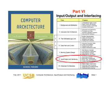
Cluster When OS writes some information on the hard disk, it does not allocate the space sectorwise, instead uses a new unit of storage called “Cluster” Clusters are the minimum space allocated by DOS when storing any information on thedisk Even to store only one byte long information on the disk requires minimum one clusterarea on the disk surface A cluster can be made up of one or more sectors, it depends on disk type being used. This reduces the size of FAT that DOS uses to keep track of the used and the empty diskspace First cluster no. is taken as 2 Clusters are used to allocate the storage area for data area only, FAT and directory areasare not allocated according to the cluster sizeCylinder: (Diagram optional); If given, Diagram- ½M.Cylinder Same tracks of different platters form an imaginary cylinder like structure Data is stored cylinder by cylinder6 Page
All tracks on a cylinder are written and then the R/W head moves to the next cylinder.This reduces movement of R/W head and increases the speed of read and write operationSector A track is a big area to store data( 5000 bytes). Hence tracks are divided into sectors The formatting program divides disk surface into sectors by writing magnetic pattern ondisk surface Different HDD capacities have different number of tracks 512 byte data can be stored in each sector. Sector no. starts from 1Landing zone: This setting specifies the cylinder to which the BIOS should send the heads of the harddisk when the machine is to be turned off. This is where the heads will "land" when theyspin down. Modern drives automatically park the heads in a special area that contains nodata when the power is turned off. Therefore this setting is meaningless and is typicallyignored. Most BIOSes set this value to be the largest cylinder number of the logical geometryspecified for the disk when auto detection takes place. So if the drive has 6,136 logicalcylinders, the landing zone will be set to 6,135. In any event a modern IDE drive willignore this setting and auto-park by itself.Zone Recording One way to increase the capacity of a hard drive during the low level format is to createmore sectors on the disks Outer cylinders than on the inner ones.Because they have a larger circumference the outer cylinders can hold more data. Drivesthat use zoned recording split the cylinders into groups called zones, with eachsuccessive zone having more sectors per track as you move outward from the center ofdisk.7 Page
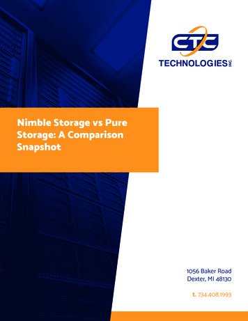
With suitable diagram explain write precompensation. (Diagram 2 M, explanation -2M)Write Pre-compensation It is useful for drives using standard track, sector format Drives using zone bit recording do not require any write pre- compensation The magnetic particles used to write on the disk surface have north and south poles Like poles repel and unlike poles attract In outer surface of hard disk platter, magnetic particles are far apart to be affected by theattraction and repulsion of magnetic particles In the inner tracks of the disk drive, the density of the magnetic are very high andadjacent particles start to attract and repel. This will force to change the information written on the disk To compensate for this shift of data particles due to attraction and repulsion, the drive canwrite the data apart or closer than the required position The particles will slowly shift to the required position because of attraction and repulsion This process of writing the data closer or farther to compensate for attraction or repulsionof magnetic particles is called Write pre-compensation8 Page
The cylinder from which this pre-compensation is started is called pre-compensationcylinder. This value will be used by all the cylinders that are towards the centre of thedrive.Interleave and Interleave factor Although traditionally interleaving was more a controller performance issue than driveissue modern hard disk drives with built-in controllers are fully capable of processingthe data as fast as the drive can send it All modern drives are formatted with nointerleave sometimes expressed as 1:1 interleave ratio. Interleave factor- the number of sectors that pass beneath the read/write headsbefore the next numbered sector arrives eg 1:3Master Boot Record (MBR) Short for Master Boot Record, a small program that is executed when a computer bootsup.9 Page
Typically, the MBR resides on the first sector of the hard disk or diskette that identifieshow and where an operating system is located so that it can be boot (loaded) into thecomputer's main storage or random access memory.The program begins the boot process by looking up the partition table to determine whichpartition to use for booting. It then transfers program control to the boot sector of that partition, which continues theboot process. In DOS and Windows systems, you can create the MBR with the FDISK/MBR command The MBR contains two elements;1. Executable code and2. A partition table, Which identifies each partition residing on the hard drive. The MBR executable code orprogram begins the boot process by looking up the partition table to determine whatpartition holds the operating system. This program looks for two hidden program files IO.SYS and MSDOS.SYS for DOS andexecutes IO.SYS program first. This program in turn loads MSDOS.SYS andCOMMAND.COM into RAM to complete the process of booting. From the above figure, you can see that a disk drive is composed of N sectors and eachsector is of 512 bytes. Out of the N sectors, the first sector is assigned to the Master Boot record. The first 512bytes of the BIOS is the Master Boot Record. MBR is composed of two components: aBootsrapping program and the partition table. The code can be Windows loader, Unixloaders, or a virus. Next, comes the partition table. The partition table is of 64 bytes and a 16 byte part whichtells about the partition of the disk. The MBR is very small in size. Its machine code just helps to load that sector which isresponsible for booting the associated partition.10 P a g e
Servo TechniquesThere are three different ways that the hard disk servo mechanism has beenimplemented.Wedge Servo, Dedicated Servo, Embedded ServoWedge Servo: In this implementation used in older drives, the servo information is recordedin a "wedge" of each platter; sort of like a "slice" out of a pie. The remainderof the "pie" contains data. the servo information is only in one location on the hard disk, which meansthat to position the heads a lot of waiting must be done for the servo wedgeto rotate around to where the heads are. All this waiting makes the positioning performance of drives that use thismethod painfully slow. Obsolete, this technique is no longer used.Drawback „: To position the heads, a lot of waiting must be done for the servo wedge to rotate aroundto where the heads are.Dedicated Servo: In this technique, an entire surface of one disk platter is "dedicated" just for servoinformation, and no servo information is recorded on the other surfaces.One head is constantly reading servo information, allowing very fast servo feedback, andeliminating the delays associated with wedge servo designs.11 P a g e
Unfortunately, an entire surface of the disk is "wasted" because it can contain no data.An entire surface of one disk platter is "dedicated" just for servo information.One head is constantly reading servo information.Allow very fast servo feedback.Separated heads for reading data and servo information.Eliminate the delays associated with wedge servo designs.DrawbackAn entire surface of the disk is wastedThermal recalibration is requiredThe head where data is recorded may not line up exactly with the head that is reading theservo information.Embedded Servo: The newest servo technique intersperses servo information with data acrossthe entire surface of all of the hard disk platter surfaces.Embedded Servo: (used in modern drives)Intersperse servo information with data across the entire disk.The servo information and data are read by the same head.The need for thermal recalibration is greatly reduced.The servo information and data are the same distance from the center of the disk and will expandor contract together.The servo codes are written to the disk surfaces at the time the hard disk is manufactured.Special, complex and expensive equipment is employed to record this information a servowriter.„ The servo codes Put in place for the life of the drive , ‰ Cannot be rewritten without returningthe drive to the factory.„ The heads are locked out at the hardware level by the drive's controller from writing data tothe areas where servo information is written.12 P a g e
FormattingWhat is formatting? Explain low level and high level formatting. Formatting (1 M)1. It prepares a blank hard disk for a particular OS.2. It puts magnetic marks of tracks and sectors on the platter surface.3. The storage capacity of formatted hard disk is always less than the capacity ofunformatted disk.4. A typical sector has 3 standard components.a. Identification field which contains the address of the sector i.e. the track head and the sectornumber.b. Data field which contains data recorded at a particular location. It also contains error detectionand correction codes.c. Number of gaps.FAT and root directory are also put on the platter at the time of formatting. Hard Disk requires alow level formatting and a high level formatting to make it useful for data storageLow Level Formatting (Physical or true formatting) (1 ½ M)1. It is done at the factory level. (In low level formatting all the data stored on the disk islost as the disk is physically formatted)2. It magnetically divides the disk into tracks and sector.3. Basic addressing information is written to each sector of each cylinder.3. It checks for bad sectors and maps them out.High Level Formatting (1 ½ M)1. It is done with the help of OS.2. High level Format program scans the disk for tracks and sectors marked bad during lowlevel formatting. The scanning program performs five retries to read the tracks or sectors.If the tracks are still unreadable, the area is noted as bad cluster in FAT.3. After scanning the entire disk, the drive heads return to the first sector of the partition andwrite MBR. Immediately in the next sector 1st copy of FAT is written and after that 2nd13 P a g e
copy of FAT is written. Initially FATS are blank except for the bad cluster marks foundin the initial scan.4. After the 2nd copy of FAT blank root directory is created.What is FAT? List two features of FAT 32. (1 M each)The file system in storage devices starts with FAT (File allocation Table).1. FAT refers to a data table that holds information about how and where files are stored in anypartition2. It is a kind of index used by operating system to keep track of information stored on the harddiskFAT 32 (Any Two)1. Introduced with Microsoft windows 95, supports drives up to 2 TB2. Since it can space more efficiently, it uses smaller clusters( 4 KB clusters for drives up to8 GB) fetch3. No compression or encryption available on FAT 32 file systemPartitioningCreating a partition on a hard disk drive enables it to support file systems each in its ownpartition. Three common file systems are used by PC operating today:/FAT (File Allocation Table)1.2.3.4.5.6.Developed by Microsoft for MS-DOS, MS-Windows 95,98,MeFAT located in MBR sector of bootable disk2 Important Functions of FAT;contains allocation information (in the form of linked list)Indicate which allocation units are free.It is simple and reliable. Two identical copies of FAT are used.Structure of FATPartitionBoot SectorFAT 1FAT 2(Duplicate)Root FolderOtherFolders and All Files14 P a g e
NTFS (New Technology File System)StructurePartition BootSectorMaster FileTableSystem FileFile Area1. Used by Windows NT, XP, 2000 , Server 2003, Server 2008, Windows Vista2. NTFS provides better performance, security compatibility and extendibility thanFAT3. Read, Search, Write, Recovery are done fast.4. Master File Table (MFT) contain information about all files and folders. First file onNTFS volume.5. Partition Boot Sector Start at Sector 0 to 16. First Info on an NTFS volume.Features1.2.3.4.5.6.7.8.It allows you to encrypt files and automatically decrypt them as they are read.Supports long file names upto 255 charactersSupports File Size upto 2 TBFor keeping track of clusters it uses a B- tree directoryReliable File System as compared to FATAllows Large partition sizes i.e more than 4 GBBuilt-in file compression facilityImproved Security And access control deciding who can perform what sorts of operationson various data within the file systemCompare FAT 16, FAT 32, NTFS (Any four points – 1 mark each)CriteriaOSNTFSFAT 32Windows 2000, XP, DOS V7,2003 server2000,98,XPMaximum Vol SizeMax. Files on VolMax file size2TBUnlimitedLimited by vol size32GB41943044GB2GB655362 GBMax Cluster numberBootsectorlocationCompressionBuilt in securityRecoverabilityUnlimited1st and last4177918First sector andcopy in sector No 6NONONO65524First sectorYesYesYesFAT16Win Dos , All version ofWindowsNONONO15 P a g e
performanceHigh on large vol Good on small vol, Good on small vol,Low on small volLow on largeLow on largeSecurityFolder andaccesscancontrolledindividuallyfie Very littlebeVery littleHDD Interface TypesInterfacing means connecting the hard disk drive to the main computer system.1) PATA Parallel Advanced Technology Attachment(IDE)IDE stands for integrated Drive/Device Electronics In ST-506/412 interfaces the controllercard was with the expansion slot and the drive was connected through cables.Features1.2.3.4.Proven and reliable technology integrationUpto 133 MB/s interface transfer ratePATA allows cable lengths upto 18 inches(46 cms)Designed for desktop PCs and Notebook PCs with usage in entry servers andconsumer electronics as well5. PATA is based on the original IBM PC ISA bus1) SCSI(pronounces as scuzzy) Small Computer System Interface1. This interface is not a drive level interface but it a system levelinterface. SCSI is not a controller for a single device.2. SCSI interface is used in high endconfigurations IDE is used in low endconfigurationFeatures1. Fast and wide Data Path2. Supports upto 7 peripheral Devices such as CD-Rom, scanner that can attach to asingle SCSI port3. Faster than the average parallel interface4. It will allow data transfer upto 100 MB/s to 160 MB/s5. SCSI is now plug and play in nature such as automatic SCSI ID assigning andtermination16 P a g e
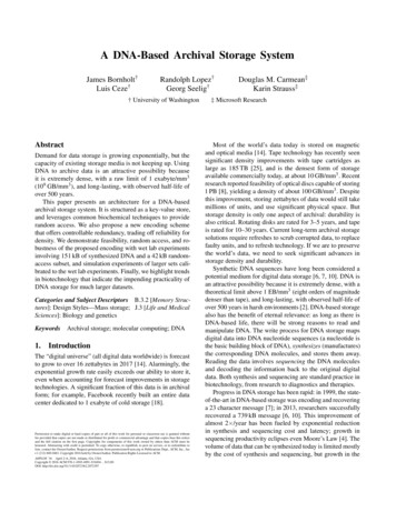
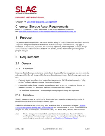
2) SATA (Serial Advanced Technology Attachment)- Is a computer bus primarily designed for transfer of data between a computer and mass storagedevices such as hard disk drives and optical drives.Features1.2.3.4.SATA is better more efficient interface than the dated PATA standard.It supports hot swappingSerial ATA uses only 7 conductors while PATA uses 40.Data Transfers at the rate of 1.5 Gbit/s, 3 Gbit/s and 6 Gbit/sCD ROM RecordingExplain working of CD-ROM drive with block diagram. (2 Diagram; 2 M working)Fig: Block Diagram of CDROM drive1. The laser diode emits a low –energy infra red beam towards the reflecting mirror2. The servo motor positions the beam onto the correct track on the CD ROM bymoving the reflecting mirror3. When the beam hits the disc, its reflected light is gathered and focused through thefirst lens beneath the platter, bounce off the mirror and sent towards the beam splitter4. The beam splitter directs the returning laser light towards another focusing lens5. The last lens direct the light beam to a photo detector and convert the light intoelectric impulsesThese incoming impulses are decoded by the microprocessor and sent along to the host computeras data17 P a g e
Recording of CDROM Drive-EFM (Eight to Fourteen Modulation) is an encoding technique used by CDs andprovides a way of countering errors by encoding a byte into 2 bytes.Using EFM data is broken into 8 bit blocks(bytes)Each 8 bit block is translated into a corresponding 14 bit codeword using a predefinedlookup table.-Digital Versatile Disc1.2.3.4.Optional storage media for storing dataUses primary for movies softwares and data backup purposeDVD holds about 7 times more data than CD DataDVDs can store more data than CDs for a few reasons:Higher-density data storageLess overhead, more areaMulti-layer storageComparison of CD and DVDParameterCDDVDSides11 or 2Layers11 or 2Capacity (GB)0.68 GB4.7-17 GBTrack pitch(µ)1.60.74Minimum pit0.830.4780650Remarkslength(µ)Wavelength(nm)Of laser diodepickup18 P a g e
TracksYesNoDVD uses filesnot tracksDVD physical disc formatsSr. NoFormatCapacityLayersSides1DVD 54.7 GB112DVD 98.54 GB213DVD 109.4 GB124DVD 1817.08 GB22Blu –Ray Disc Blu ray also known as Blu-ray Disc(BD is a next generation optical disc formatjointly developed by members of the Blu-ray Disc Association(BDA) – a groupof the world’s leading consumer electronics, personal computer and mediamanufactures (including Apple, Dell, Hitachi, HP, JVC, LG, Mitsubishi,Panasonic, Pioneer, Philips, Samsung, Sharp, Sony, TDK and Thomson) The format was developed to enable recording, rewriting and playback of HighDefinition Video (HD) as well as storing large amounts of data. The format offers more than five times the storage capacity of traditional DVDsand can hold upto 25 GB on a single layer disc and 50 GB on a dual layer disc. A blue laser is used to read the media. Blue light has a shorter wavelength thanred used by previous technologies. This makes it possible to read data withgreater precision.19 P a g e
Blu –Ray Disc SpecificationSpecificationValueSpecification23.3 GB/25Capacity (SingleLayer)GB/27 GBValue0.32µmTrackingPitch46.6 GB/50Shortest pit0.160/0.149/0.138Capacity (DualLayer)GB/54 GBlengthµmLaser WaveLength405 nm 0.85Data transferRate36 Mbps120 mmRecordingformatPhase ChangeRecording1.2 mmTrackingformatGrooveRecording0.1 mmVideoFormatMPEG2Lens NumericalApertureDisc DiameterDisc thicknessOpticalProtection Layer20 P a g e
Recording Techniques: FM, MFM , RLL, perpendicular recording Describe Modified Frequency Modulation (MFM) and Run Length limited (RLL) techniques of recording with suitable example. (For MFM explanation 2 marks, Waveform or coding 2 marks) (For RLL explanation 2 marks, Waveform or c