Transcription
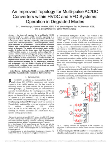
An Improved Topology for Multi-pulse AC/DCConverters within HVDC and VFD Systems:Operation in Degraded ModesD. L. Mon-Nzongo, Student Member, IEEE, P. G. Ipoum-Ngome, Tao Jin, Member, IEEE,and J. Song-Manguelle, Senior Member, IEEEAbstract— An improved topology for a multi-pulse AC/DCconverter-based on 6-pulse rectifier modules operating in adegraded mode is described. Its main application is HVDC andVFD systems, where reliability, availability, and maintainabilityare the most critical requirements. A new concept called, “threephase electronic Z/z transformers,” which provides separatedvoltages with reconfigurable phase-shifting angles and voltageratios, is discussed. The number of acceptable faulty rectifiermodules is defined at the design stage. Such features enableAC/DC rectifier systems to be modular and reconfigurable. Incontrast with conventional topologies, the proposed structure canoperate optimally as an 18-pulse, 12-pulse, or 6-pulse rectifier infaulty conditions of local transformers or rectifier modules. Animplementation method for a degraded 24-pulse rectifier with itscontrol architecture including the Z/z transformers’ commandunit is discussed. A 1.5 kV, 18 kVA, 18-pulse AC/DC converterassociated with a real-time system control is designed and tested.Promising results validate the new concept.Index Terms— Multi-pulse AC/DC converter, HVDC, VFD,reliability, degraded mode, electronics Z/z transformer.I. INTRODUCTIONa) Conventional multi-pulse AC/DC. This rectifier is theearliest and most widely known technology that is used withinHVDC and VFD systems. It is efficient and gives a largeamount of power, it is also reliable, and its architecture mayallow it to continue to operate even in faulty conditions [5] [7]. Fig. 1a is a 12-pulse rectifier-based thyristor which is alsoknown as a 12-pulse LCR (load commutated rectifier). It is acurrent source converter that consists of a 12-pulse transformer(or phase-shifting transformer) and two series-connected 6pulse rectifiers. The shifting angles ( 1 0 and 2 30 )between each secondary winding and the primary winding ofthe transformer are key elements for obtaining pulsating DCpower with reduced voltage ripples and current harmonics atthe grid side.However, the structure of the 12-pulse transformer does notenable the rectifier to operate efficiently in a degraded mode.For example, a severe failure in any part of a transformer mayresult in a total system shut down if no redundant transformeris installed; additionally, including a redundant transformer willincrease the size and cost of the rectifying system.RELIABILITY, availability and maintainability (RAM) ofhigh-voltage DC (HVDC) transmission and variablefrequency drive (VFD) systems are the key criteria toeffectively secure the global demand for the generation ofelectric power [1] - [3]. In these systems, the load commutatedconverter (LCC) technology for very high-power AC/DC andDC/AC conversion not only provides pulsating DC or ACpower, but also an efficient and high-power quality interface toAC systems (e.g., grid, motors) [1] - [4], [3] - [6]. In addition,there is the need to study the reliability of multi-pulse LCC inthe Zhundong-Sichuan HVDC project which was launched inChina to better understand the power and investments involvedinmakingmulti-pulseLCCreliable(2015, 1100 kV, 10 GW, 2600 km) [6]. Figure 1 is asummary of potential candidates for a multi-pulse AC/DCrectifier for high-power systems. Manuscript received January 22, 2017; revised June 08, 2017, August07, 2017 and September 13, 2017; accepted September 25, 2017. Thiswork was supported in part by European Community 7th frameworkprogramme (Number: 909880). (Corresponding author: Tao Jin)D. L. Mon-Nzongo, P. G. Ipoum-Ngome and Tao Jin are with theElectrical Engineering Department of Fuzhou University, Fuzhou,350116, China (e-mail: monnzongo@fzu.edu.cn; ipoum24@yahoo.fr;jintly@fzu.edu.cn).J. Song-Manguelle is with ExxonMobil Development, Houston, TX77060-1905 USA (e-mail: joseph.m.song@exxonmobil.com).0 30 0 30 30 3 30 330 30 333 30 Tx (1,2,3,4) 30 33Fig. 1. Topology candidates for high-power AC/DC converters: (a)conventional 12-pulse converter, (b) modern 12-pulse converter, (c) proposedtopology.b) Modern multi-pulse AC/DC rectifier. To overcome the issuerelated to single-thread 12-pulse converters, series, or parallel0278-0046 (c) 2017 IEEE. Personal use is permitted, but republication/redistribution requires IEEE permission. See http://www.ieee.org/publications standards/publications/rights/index.html for more information.
connections of two or more 12-pulse converters have beendeveloped in many projects [1,5,6]. Fig. 1b shows an exampleof a 12-pulse rectifier with two threads or modules (12-pulsetransformer and rectifier) connected in series at the DC side. Incontrast to the topology shown in Fig. 1a, this setup cancontinue to operate as a single-module 12-pulse rectifier in thecase of failure of one module.The main drawback of this topology is the poor currentharmonic performance at the grid-side, since it always operatesas a 12-pulse rectifier in a normal or degraded mode of onemodule. Therefore, it requires the same filtering devices of thesame size as a single-thread 12-pulse rectifier shown in Fig. 1a.The use of filtering devices in high-power systems may increasethe risks of electrical resonance with AC systems (e.g., electricnetwork, AC motors).The topology shown in Fig. 1b can be improved to operate as a24-pulse rectifier in normal mode if only the two windings atthe primary side of the 12-pulse transformers are configured ina zigzag to generate phase shifting angles of 7.5 and 7.5 .However, in this configuration, the 24-pulse rectifier can onlyoperate as a 6-pulse rectifier in a degraded mode, since thephase-shifting angle does not correspond to an 18-pulse or 12pulse operation.c) Proposed topology: Using the same number of 6-pulserectifiers as shown in Fig. 1b but with four separated threephase variable phase shifting transformers instead of two 12pulse transformers, we propose a new topology, as shown inFig. 1c. The proposed topology operates as a 24-pulse rectifierin its normal mode and, respectively, as an 18-, 12- and 6-pulserectifier in the case of one, two or three faulty modules in thedegraded mode. Compared to the topology of Fig. 1b, thistopology can withstand the same amount of power when usingthe same power rating as its transformers and rectifiers.Moreover, it generates fewer AC components superposed to theDC-side voltage and fewer current harmonic componentspropagated at the grid side.In practice, three-phase transformers are easier tomanufacture compared to multi-pulse transformers; thus, theproposed topology operating in normal mode with a constantphase-shifting angle can be less expensive than standardtopologies. In this paper, the variable three-phase-shiftingtransformer is called the electronics Z/z transformer, since itsphase-shifting angle and voltage ratios are both variablethrough the electronics interface associated with the tap changeof each of the windings. The choice of adding this electronicfunction to the three-phase transformer will depend on thedesign objective and the investment involved because theadditional electronic function is only activated in a faultycondition and requires additional switches and a controlalgorithm to operate in a degraded mode.The traditional topologies of multi-pulse AC/DC convertersoperating in a degraded mode are described in section II, andthe proposed topologies are described in section III.The new concept, an electronics Z/z transformer is described insection IV. An experimental prototype of an 18 kVA, 1.5 kV,18-pulse AC/DC converter with the associated control systemhas been designed and tested to validate the proposed concept.Simulation and experimental results are discussed in section V.II. THE TRADITIONAL TOPOLOGY OF A MULTI-PULSEAC/DC RECTIFIER OPERATING IN A DEGRADED MODEFig. 2 is an example of a standard rectifier topology adoptedin high-power HVDC or VFD systems [1-5]. It is a 24-pulserectifier system including a set of phase-shifting three-phasetransformers and four series-connected 6-pulse rectifiermodules. For this specific configuration, there is a 15 phaseshift between the secondary side voltages of the transformer.To increase the availability of such system, the input rectifiersystem should tolerate faults occurring in a partial module (M1to M4), therefore output DC bypass switches have been insertedin Fig. 2. For the system to operate with failed modules, thevoltage phase-shift should be changed from 15 to 20 , then30 for respectively a healthy system, a degraded 18-pulse withone failed module and a degraded 12-pulse with two failedmodules for example. Unfortunately, since the voltage phaseshifting angles are all constant per design, it might becomechallenging to fulfil the grid side current harmonicrequirements such as specified in international standard [17].From Fig. 2, let’s consider( , , , and)( , , , as) twocomplementary switches associated to each partial module. Ifonly one module is faulty, then 0 and 1 ; theremaining modules can continue to operate but with a reducedpower.Fig. 2. Traditional 24-pulse rectifier with additional bypass switchesConsequently, per current phasor summation requirement,the system can only operate in 18 or 12 configurations if thephase shift angles of each case are respected ( 15 20 ).This is particularly true in VFD applications where a floatinggrounding point is used on the DC-side (i.e., the DC-link is notgrounded). In such case, the system is only grounded in theprimary side of the multi-secondary transformer. As a result,the system can operate safely and can be downgraded (with areduced power rating) from a 24-pulse rectifier to an 18, 12 oreven 6-pulse rectifier.In HVDC transmission systems with a 24-pulse rectifier,three DC cables are used: positive and negative rails use a0278-0046 (c) 2017 IEEE. Personal use is permitted, but republication/redistribution requires IEEE permission. See http://www.ieee.org/publications standards/publications/rights/index.html for more information.
returning DC cable connected at the center point of the systemin order to carry more power and also to limit the groundingvoltage and voltage stress on the power modules. A failure of asingle module on the positive rail, for example, requiresbypassing an extra module on the negative rail (with a 50%power reduction) and leads to a 12-pulse rectifier system.Table I shows all possible faulty modules and switches statesfor a VFD system to operate in a degraded mode. This table isnot applicable to HVDC systems with three-pole cables.TABLE I: POSSIBLE OPERATING MODES OF A 24-PULSE RECTIFIER INFAULTY CONDITION OF A PARTIAL 6-PULSE MODULEM1M2M3M4k12k 22k 23k s consider the following notation( , , ,) 0corresponds to a healthy module, while ( , , , ) 1 is for afaulty module. In general, if is the number of modules, thesystem will generate p-pulse on the dc side (with 6 ), withthe secondary side voltages of the transformer regularly shiftedby 60/ degrees. Consequently, 22 corresponds to 14possible failures. In the S1 solution (see Table I), using astandard 24-pulse rectifier with additional bypass switches asshown in Fig 2, there are six possibilities to operate in adegraded mode: two modes as 12-pulse rectifier (12P) and fourmodes as 6-pulse rectifier (6P). During each mode, thepulsating DC power transferred to the dc link correspondsrespectively, to a half and a quarter of the total power undernormal operation (no faulty module). Conversely, the topologyshown in Fig. 2 is in opposition to optimal an operation in adegraded mode, since it leaves 8 modes among 14, where a 24pulse rectifier can no longer operate in analytical conditions forcurrent harmonic cancellation [4].Therefore, a solution based on a Z/z transformer has beenproposed. The resulting number of pulses in degradedconditions are shown in table II (see S2 column). With theproposed approach, all 14 possibilities can lead to a systemoperating in a degraded mode with a substantially high numberof pulse as indicated in Table II. Among them, there are 04modes corresponding to 18-pulse (18P), 06 modes to 12-pulse(12P) and 04 modes to 6-pulse (6P) rectifiers. Thus, the sameinstallation of a 24-pulse rectifier can operate as three differentnumber of pulse in a degraded mode, without adding any newfull three-phase transformer to the system. However, asupplementary circuitry will be required as discussed in the nextsection.III. PROPOSED TOPOLOGY: Z/Z TRANSFORMERBecause of the significant investment involved in highpower HVDC systems such as those listed in [6], ongoingHVDC projects in China are intensifying research regardingfault-tolerance techniques in AC/DC and DC/AC systems.Recent investigations in this area are mainly focused on thepower conversion stage with IGBTs or IGCTs, and their controland modulation strategies, [9]-[11]. This section describes anapproach focused on increasing the availability of a multiwinding transformer and multi-pulse rectifier system for HVDCtransmission systems, by using separated three-phasetransformers with adjustable phase-shift angles of their voltage,instead of a single multi-secondary transformer with constantangle per design. Obviously, the proposed solution is alsoapplicable to large VFDs with tight requirements on grid sidecurrent THD.Fig. 3. Proposed topology for a 24-pulse rectifier-based four Z/z transformers,that provides variable-shifting angles and turn ratios.Figure 3 shows the simplified single-line diagram of theinvestigated topology for a specific case of a 24-pulse AC/DCconverter. The configuration can also be used on the inverterside of a load-commutated-inverter drive or on the receivingend of an HVDC system with minor modifications and forhigher number of pulses. The architecture is based on the seriesconnected 6-pulse rectifier modules supplied by electronic Z/ztransformers that enable possible operation in a degraded modeby providing the corresponding phase-shifting angles.The topology uses four separated three-phase transformers,where the primary and secondary windings are initiallyconfigured in a zigzag formation and includes tap-changingwindings that can be adjusted through power switchesconfigured as described in the next section in order to obtainadjustable phase-shifting angles and voltage ratios. The systemcan also be used with traditional tap-changing switches. If onemodule is faulty, the remaining transformer’s phase-shiftingangles will be adjusted to generate the corresponding angles and0278-0046 (c) 2017 IEEE. Personal use is permitted, but republication/redistribution requires IEEE permission. See http://www.ieee.org/publications standards/publications/rights/index.html for more information.
voltage ratios to operate as an 18-pulse rectifier and to maintainthe adjusted amount of power. These angles are, respectively 20o, 0 and 20o. The voltage ratio can be kept equal to 1/4 ofthat in the normal mode or can be increased to 1/3 in order tocompensate for the diminution of power due to the faultymodule, which is bypassed.However, it is challenging to have an exact voltage boost tocompensate for the loss of power; therefore, a slight decrease inthe overall power is expected. Normally, the system should bedesigned with a sufficient voltage margin such that during thetransformer reconfiguration the transformer voltage is slightlyboosted to compensate for the possible voltage loss due to thebypass of the faulty module.As explained in section II, solution S2 shown in Table I,indicates all possible modes that can be obtained. They aredependent on the number of faulty six-pulse modules.Unfortunately, increasing the number of components willreduce the system reliability, and consequently, they should beincluded in the plant maintenance plan. However, this solutioncan achieve greater system availability with grid-side currentTHD within acceptable margins such as the ones specified inIEEE 519 [17] as well as reduced loss of power when at leastone module is faulted and bypassed.IV. AN IMPLEMENTATION METHOD OF A THREE-PHASEELECTRONICS Z/Z TRANSFORMERA. General PrincipleFig. 4. General principle of a three-phase electronic Z/z transformer: (a)Transformer connected in Z/z, (b) taps change variation principle.Figure 4 shows the configuration of the windings and the stepvariation mechanism of an electronic Z/z transformer. Theprimary and secondary windings consist of ( , , , windings.)andare located on the primary side, whileandarethose located on the secondary side, as shown in Fig. 4a.Initially, the primary and secondary windings are in a zigzagconnection (Z/z). By knowing that the Z/z connection is thecombination of the wye and delta connections, it is possible toobtain one of them by properly selecting the tap level of eachwinding. For example, if 0 and 0 the transformerhas a wye-wye (Y/y - 0 ) formation. Similarly, if 0 and 0 the transformer is configured in wye-delta (Y/d - 30 ).Thus, the Z/z transformer represented in Fig. 4a can beconfigured to adjust predefined phase shift angles.Each winding ( , , , )in Fig. 4a consists oftapingcoils, as shown in Fig. 4b. The windings variation principle isto step the cursor ′ fromto 0 or in the reverse direction.or is betweenWhen the tap cursor of windings 0 ′ , the windings are connected in a zig-zagformation. They are configured in delta or wye connectionswhen the cursor is at the same position as 0 or. Thediscrete change of the phase-shifting angle and the winding turnratio is adjusted to define the correct value oftoin adegraded mode and are pre-designed as described in [4].B. Summarized voltage phasor analysis for the tapchange windings designFigure 5 shows possible configurations of a Z/z transformer.To design each tap winding, consider 0 and the phaseshifting angle defined as 0 30 . For this case, the Z/ztransformer which was shown in Fig. 4a becomes equivalent tothe structure represented in Fig. 5a-1 and its equivalent phasordiagram is presented in Fig. 5a-2. In the same way when 0 and the phase-shifting angle defined as 30 0 , theZ/z transformer of Fig. 4a becomes equivalent to Fig. 5b-1 andits voltage phasor diagram is shown in Fig. 5b-2. Applyingbasic trigonometric formulas to these two phasor diagrams, forandthenrespectively the triangleandrespectively as shown in Fig. 5a2 and Fig. 5b-2, we obtain Eq. (1) and Eq. (2) given below. It isthese equations which are used to preset the number of turns ofeach tap winding corresponding to a specific operating mode.Fig. 5. Different configuration of a Z/z transformer. a-1) Y/z transformerconnection; a-2) phasor diagram. b-1) D/z transformer connection; b-2) phasordiagram. N4 N N 34 N1 N 3 N 4 N4 N3 N 4 N2 N N4 3 V4 sin(30 ) Vax sin(30 )VVAB1 Ax Vax 2sin(30 ) Vab V4sin( ) Vax sin(60 )VVAB3 Ax Vax 2sin(60 ) Vab(1)(2)In practice, it is very difficult to obtain more than two faultyrectifier modules at the same time. Therefore, the realistic caseconsists to design a Z/z transformer that can operate from 24-0278-0046 (c) 2017 IEEE. Personal use is permitted, but republication/redistribution requires IEEE permission. See http://www.ieee.org/publications standards/publications/rights/index.html for more information.
pulse to 18-pulse rectifier (with two modes only). Thus, thephase-shifting angles are respectively 0, 15 , 30 for a normalmode operation, and 0, 20 in a degraded mode operation.When the number of operating mode is known, the number oftap windings is defined (two taps for this case) and the topologyof the power switches associated to these tap windings is alsoderived as explained in next section.C. Implementation for a 24-pulse rectifierAn example for the implementation of Z/z transformers for a24-pulse rectifier with the original phase-shifting angles of 0, 15 and 30 is shown in Fig. 6. These angles should bereadjusted to 0, 20 in a faulty condition. Their primarywindings are configured in Y-grounded with bidirectionalpower switches associated to the secondary windings to achievethe discrete variation of the transformer’s phase shift angle.Fig. 6. Detailed windings and power switches configuration a) positive and b)negative phase-shift.Fig. 6a shows the detailed connections of the transformer’swindings for generating negative phase-shifting angles. In Fig.6a-1, the first set of windings generates the phase-shifting angleof 15 when the power switchesandare closed andandare open. Otherwise it produces a phase shiftof 20 . The transformer configured as shown in Fig. 6a-2generates 20 whenandare closed andandare opened. Otherwise, it produces a phase shift of 0 . Fig. 6bshows the detailed connections of three-phase transformer’swindings for generating positive phase-shifting angles. In Fig.6b-1, a 15 phase-shift is obtained whenandareclosed whileandare opened. 20 is obtained from,are closedthe transformer shown in Fig. 6b-2 whenwhile,are opened. Otherwise, these transformers willgenerate the phase shift angle of 0 (Fig. 6b-1) and 30 (Fig.6b-2).V4 Vab AB V1 33 sin 30 V V 2sin30 (3) 1 sin 30 ab3 3 V V 2sin 30 ab 43The four transformers configured as shown in Fig. 6 havetwelve power switches per transformer. If a fault occurs in onlyone of the rectifier modules of the 24-pulse rectifier, the systemis downgraded to an 18-pulse rectifier by adjusting the voltagesacrossand . The desired voltage and phase-shifting angleare pre-designed as described previously and the final equationsto obtain the voltage across each tap winding are given in Eq.(3).The additional power losses due to the power switches havebeen estimated to 0.15% of the global DC power that can begenerated by each six-pulse rectifier module for a 10 MW VFDsystem. We emphasize that, the losses calculation was based onthe IGBT FZ1200R17HE4P of Infineon with the rated power of2 MW and dynamic characteristics described in [21]. We havealso assumed that the conduction losses of the IGBT antiparalleldiode and switching losses are negligible since in this utilizationthe power switches do not continuously switch in steady stateas it would be in VFD application. Only the on-state conductionlosses were considered. Thus, for the implementation of aninput transformer of a 24-pulse rectifier configured as shown inFig. 6, the power losses will be approximately 15 kW pertransformer.D. Control architecture for a 24-pulse rectifier systemFigure 7 shows a high-level overview of the system controlarchitecture of a multi-pulse LCI, with p-pulse on the rectifierside and q-pulse on the inverter side. A similar configurationcan be adopted for HVDC transmission system as shown in Fig.8. Each power conversion unit (Rectifier or sending-end,inverter or receiving end) has a dedicated slave controllersynchronized through the grid-side or motor-side voltage, andthey are supervised by two independent master controllers. Thetransformer has its own controller integrating protectionfunctions. In VFD applications these functionalities can beintegrated to one physical controller, with some of thetransformer protective functions handled by industrialprotective relays [16], [18-19].Fig. 7: High-level overview of the control system of a multi-pulse LCI VFDFigure 8 shows a detail functional architecture of the rectifieror sending-end power converter unit. Each rectifier module hasa local slave controller for its gating, protective functions andgrid synchronization. There is a master controller for the startupand shutdown sequential control, a closed-loop controller for0278-0046 (c) 2017 IEEE. Personal use is permitted, but republication/redistribution requires IEEE permission. See http://www.ieee.org/publications standards/publications/rights/index.html for more information.
speed or torque (VFD application) as well as the control of DClink current (e.g. internal VFD DC-link or transmission currentcontrol). And finally, there is a Z/z transformer commandmodule with monitoring, gate drivers level and power systemprotective functions with relaying per IEEE C37.2 standard[16]. This module is taking of the transformer reconfigurationthrough the power switches.Fig. 8: Control architecture of input rectifier with a Z/z-Transformer.In general, the control strategy for the local controller usedin standard VFDs and HVDC systems is often based on linearcontrollers (PI regulators with possible decoupling network andanti-windup strategies), the synchronization unit is a phaselocked-loop (PLL) which is based on a voltage controlledoscillator in series with a low-pass filter for the control of theangular frequency of the grid voltage or motor-side back EMF(in VFD systems). Initial implementation for such functions canbe found in most of commercial time-domain transientsimulator software in electrical engineering [22-24]. Forexample, a model for implementing a single pole HVDC systemincluding all functions as represented in Fig. 8 is available inthe library models of [22]. Similar master/slave controller canbe found in [5].E. Notes on industrial system implementationFor industrial systems, there is no need for a special faultdetection circuit. Instead, existing protection features for suchsystems can be used. These features include the following [16]:i) transformer monitoring and protection through industrialprotective relays, such as instantaneous overcurrent (50), ACtime overcurrent (51), as well as differential protection relays(87); ii) sending-end converter overcurrent protection(instantaneous and AC time overcurrent, 50/51); iii) undervoltage protection (27) and under-frequency protection (81U);iv) overall converter monitoring system resulting from thegate drivers; and v) earth-fault protection in the power stages.In addition, because of the power level and voltage rating oflarge power systems (e.g., HVDC and large VFDs), it isbeneficial to clearly state that the system should not bereconfigured online. All the aforementioned fast protectivefunctions should act normally to protect the integrity of thesystem, including opening the main breaker, which may lead toa partial system shutdown if required.Usually, the reconfiguration of the system should be decided bythe plant electrical team after a trip and also as a result of a quickroot cause failure assessment. Once it has been confirmed thatthe fault is only impacting a rectifier module, the electrical teamcan proceed with system reconfiguration. Such an approach isrecommended in industrial applications in order to avoidconsequential failures of other parts of the power system thatmay result from the transient behavior of faulted powerequipment.A control algorithm that takes into account a pre-identifiedsystem reconfiguration and that is based on Table I will bedeveloped and executed through the HMI control panel. Areconfiguration guide should be provided to the electrical teamin order to easily resume the system operation in a degradedmode. Specifically, for HVDC applications, the management ofthe failure of one module on the positive or negative pole shouldbe done during the design stage as follows:i) A system should be designed with a 25% voltage margin:in the design stage, the overall system can be designed to output125% of the needed power in order to achieve a global 25%power redundancy. In that case, bypassing a healthy rectifiermodule will reconfigure the rectifier side from a 24- to a 12pulse system; this will then achieve 75% of the nominal poweravailable instead of 50% if the system is designed without avoltage margin.ii) A system designed with a 25% voltage reserve and a 25%current margin: more power might be achieved if the designteam decides to select the overall current transmission with upto a 25% current margin combined with a 25% voltage reserve.In that case, once the system is reconfigured from 24-pulse to a12-pulse degraded mode, the current reference is ramped to125% of the nominal transmission power; therefore, theachievable power can reach approximately 93.75% of itsnominal power. However, this type of design will increasetransmission losses and produce a high magnitude of low-orderharmonics. The design team should take such considerationsinto account, as well as conduct a trade-off study for selectingthe setup of the final design specifications.V. SIMULATION AND EXPERIMENTAL ANALYSISA. Simulation set-up and resultsFor validation, simulation models of a 24-pulse rectifier system,as shown in Fig. 2 and Fig. 3, have been developed with thesoftware Simpowersystems of MATLAB/Simulink. The modelof the transformers was implemented using basic single-phasetransformers with seven tap windings per device to thesecondary side for demonstration purposes only. Bidirectionalpower switches are used. The fault detection circuit wasimplemented as described in [18]. The control logic of switchesassociated to the tap windings of each transformer wasdeveloped to include all operating mode as described in TableI. The turn and voltage ratios for each mode were pre-calculated0278-0046 (c) 2017 IEEE. Personal use is permitted, but republication/redistribution requires IEEE permission. See http://www.ieee.org/publications standards/publications/rights/index.html for more information.
as described in Eq. (1) and Eq. (2). These values were used toconfigure the primary side of the transformers and then identifythe desired number of windings at the secondary side. Theparameters of the simulation are shown in Table II, and theresults are shown in Figure 9.TABLE II :ParametersSupply voltageSupplyfrequencyLine reactorTransformersPAR
modules is defined at the design stage. Such features enable AC/DC rectifier systems to be modular and reconfigurable. In contrast with conventional topologies, the proposed structure can operate optimally as an 18-pulse, 12-pulse, or 6-pulse rectifier in faulty conditions of loc