Transcription
Electrical Systems & Troubleshootingfor Landscape Irrigation Systems
ElectricityWhat is electricity? It is a lot easier to describe what electricity does than what it is.it operates ourlights and runs our air conditioners and electric motors.Electricity - a form of “energy” similar to chemical and mechanical energy.*Electricity is the most widely used form of energy ranging from miniature batteries andpower use devices in your wristwatch to melting steel in large arc furnaces.*That still doesn’t tell us what it is.Electricity - the flow (movement) of electrons through a material.*You may remember from science class that atoms are made of protons, neutrons, andelectrons.*When electrons move from one atom to another, electricity flow has occurred.*This flow of electrons is what causes lights to operate or motors to turn.We can't see electricity, but we can see its effects, such as light or heat.*Electricity must be converted to other forms of energy such as heat, light, or mechanicalpower to be useful.*In fact, Edison himself never thought electric power could be sold, since power itself had no“value.” He thought people would have to be sold light or heat – a thought that is comingback into vogue at this time with “end-use pricing”.1
Types of ElectricityThere are two basic types of electricity; direct current (DC) and alternating current (AC).Direct Current (DC)Direct current is a type of electricity in which theelectrons flow only in one direction.DC electricity is utilized in many applicationsincluding most battery operated devices and internallyfor most electronic and computing devicesDC power can be produced by several commonmethods including:batteries, solar panels, fuel cells, and special DCgenerators like wind turbines.Alternating Current (AC)Alternating current is electricity in which the movement of electrons is first in one direction and thenreversed and moving in the opposite direction.AC electricity is utilized in most lighting, heating,and motor applications supplied by power fromthe electrical grid.AC power is produced using an AC generator.AC has a distinct advantage over DC forcommercial electric power systems.AC voltage and current can be varied at will usingtransformers which makes economical transfer oflarge amounts of electricity over long distancespossible.2
ConductorsMaterials that are made up of atoms which readily allow their electrons to be transferred from atomto atom are called conductive materials or "conductors" for short.Soft metals like platinum, gold and silver allowtheir electrons to flow very readily from atomto atom and since these materials allowelectrons to move very easily, they make thebest conductors of electricity.Copper and aluminum are good conductors ofelectricity that most electric wires or“conductors” are commonly made from.Copper WireCopper wire is used as an electrical conductor primarily on the customer side of the electric meter.Wires installed in the walls of most residences are most likely made of copper.Aluminum WiresAluminum wires are used as electrical conductors on the electric utility transmission and distributionsystems.The overhead wires running on the utility poles are made of aluminum and do not haveinsulation around them.Copper vs AluminumCopper wires generally cost more than aluminum wires but have some advantages like lessmaintenance requirements in homes and businesses.Copper is a better conductor than aluminum so a smaller copper wire can be installed inmany instances compared to an aluminum wire.Copper wires are required by most national codes to be used as the conductor material forwiring most residential type locations.Aluminum wires may also be allowed in some areas but you should always check with thelocal electrical inspector or building code authority first.Aluminum’s two advantages over copper as a conductor for utility lines include its lightweight and lower cost.3
InsulatorsMaterials that are made up of atoms with the electrons tightly bound to the nucleus which do notflow easily are called insulating materials or "insulators" for short.Glass, rubber, porcelain, and most plastics are examples of good insulating materials.These materials do not readily conduct electricity since their electrons do not move easily from atomto atom.“Insulators” are used to prevent the flow ofelectricity.Insulating materials are put on the outside ofextension cords and appliance cords to preventus from being shocked when we plug and unplug them.Question: How about wood.Is it an insulatoror conductor?Answer: It depends on the moisture contentof the wood.In its dry processed form like the top of a wooden desk, wood is a good insulator. In its live growingstate with sap it like a tree branch, wood can be a good conductor of electricity.It is important to remember that many materials can be either an insulator or conductor depending ontheir moisture content or condition.4
4. Voltage (Volts) - E or V Voltage or volts for short, is the electrical force that pushes the electrons from atom to atom througha material."Volts" are a measure of the "electrical pressure" and denote the force with which electricity isflowing through a wire at a given instant of time. (Some engineers use the word "potential" as aninterchangeable word for "voltage".)Just as water needs some pressure to force it along in a pipe, so electricity needs some force to makeit flow. In the water pipe, the pressure is in pounds per square inch. In an electrical circuit pressureis measured in volts. Given the same size of water hose, if the water pressure increases, the volumeof water increases. In an electrical circuit, the higher the voltage, the more amps it can push throughthe conductor in a certain time period. If there is novoltage difference between two items, then noelectrical flow between the two items occurs, sincethere is no pressure difference to force the electrons tomove between the two items.The voltage is supplied by the electrical source,typically either a generator or battery. This makes itsimilar to the water pump in a water piping systemwhich supplies the water pressure to push the waterthrough the pipe.The scientific symbol for voltage is an "E", dating to early days of electricity when it was called the"Electromotive force". Scientists and engineers use the "E" symbol for voltage, while electriciansand wiring books use "V" as the voltage symbol. This can create some confusion, since either mightbe used.When you think about a 120 volt outlet, know you know that the outlets circuit has 120 volts ofelectrical pressure to push electrons through the appliance.5
5. Amperes (Amps) - I or A Amperes or “amps” are a measure of the rate of “current” flow of the electricity through the materialThis flow of electrical current develops when electrons are forced from one atom to another.Using a water pipe as an analogy, the amps would be similar to the rate of flow of water through thepipe measured in gallons per minute.Think of electrical current or amps as how manyelectrons pass a given point in a given amount of time.Measuring current in electrons/second would becumbersome due to the large numbers, so think of anamp as a huge number of electrons per second.The flow of current through a conductor results in bothheat and a magnetic field being produced.HeatEvery time an electron moves from atom to atom through a conductor, a small amount of heat isproduced.The higher the number of electrons moving (amps) the more heat produced from the conductor.That is why the amount of amps flowing on a circuit is important.the more amps flowing, the moreheat that is produced.This can be important since given sizes of wire can handle only so much heat before they melt.When a wire carries more amps than it can handle without overheating, we say it is “overloaded”.Wires must be protected from too many amps so they do not melt.The scientific symbol for amperage is an "I", dating to the early days of electricity. Scientists andengineers use the "I" symbol for amperage, while electricians and wiring books use "A" as theamperage symbol. This can create some confusion, since either might be used.6
ImpedanceThe term “impedance” is used to describe the affect of various different properties that impede orslow the current flow in a wire and it is measured in units called “ohms”.The impedance of an electrical system is made up of both its resistance and reactance.Resistance is caused by the electrical properties of the wiring material itself.There are two types of Reactance.Inductive and Capacitive.Inductive reactance is caused by the constant change of the magnetic field in AC equipmentcontaining coils of wires like electric motors.Capacitive reactance is caused by capacitors.devices that store energy.ResistanceElectrical resistance is defined as the resistance to flow of electricity through a material and ismeasured is measured in units called ohms. Think of resistance as a measurement of how loosely ortightly a material holds on to its electrons. Some metallic materials like gold, sliver, copper, andaluminum have low resistance to the flow of electricity and make good conductors. They allowelectricity to flow through them fairly easily. Other materials like porcelain, rubber, plastic and glasshave a very high resistance to the flow of electricity and do not allow electricity to flow through themand make good insulators.The resistance value in ohms for most materials can be looked up in physics and other science books.Copper would have a lower electrical resistance measured in ohms than aluminum since copper is aslightly better conductor than aluminum. The lower the resistance of a material measured in ohms,the better the conductor the material is.When using a water piping system as an analogy to an electrical system, the analogy to the resistancein the water piping system is the friction in the water pipe which resists the flow of water. Severalthings can resist the flow of water in the pipe. Thingssuch as rust or corrosion inside the pipe, objects stuckinside the pipe, even the size of the pipe. The same istrue of electricity. A number of things resist its flow.Smaller wires have more resistance than largerdiameter wires. Longer wires have more resistancethan shorter wires.The scientific symbol for electrical resistance,measured in ohms, is the Greek Omega (Ù). Manytimes electricians and practical wiring books use an"R" representing resistance. This can create some confusion since either may be used.7
Electrical PowerElectrical power is a measure of the rate of work an electric current can accomplish.Think of this as how fast electrical energy is being converted into some other form of energy likelight or rotating mechanical energy.In general, the higher the power consumption of a device, the greater its ability to do work, or deliverenergy.In the electrical world, there are three types of Power; Real, Apparent, and Reactive.The difference between the real power and the apparent power is called the power factor.Real Power (Watts, Kilowatts, Megawatts, etc)Real power in a circuit is the portion of apparent power that actually does the work (convertselectrical energy into some form of useful energy either as heat or work).Real power is measured in watts or kilowatts and is what most people are referring to whendiscussing power.(Watts)Real power measured in units of watts or wattage is ameasure of the useful a device or appliance consumes.The 100 watts on a light bulb is not how much light itproduces, but how much electrical power it uses tooperate.Appliance manufacturers indicate how much electricalpower an appliance uses in units of watts, which arecommonly found on the appliance nameplate.Electric utilities measure the power usage of customers inkilowatts. 1 kilowatt is equal to 1000 watts. Utilitiesmeasure the power produced by a generator or power plant in units of megawatts. 1 megawatt 1million watts.Motor manufacturers still rate motors using the english system of units and indicate the powerproduced by an electric motor in units of horsepower. The English Unit System for measuring poweris 1 Horsepower 746 watts.Power is generally shown using a "P" as the symbol. The scientific symbol for the watt is the "W".The kilowatt is shown as "kW" with a little k and capital W. The megawatt is shown as "mW" witha little m and capital W. There are several types of power you should understand including realpower, apparent power and reactive power.8
Electrical Generation PrinciplesThere are several types of “power plants” used to make electricity including hydroelectric plants,steam turbines, gas turbines, combined cycle, nuclear plants, and newer types such as geothermal,solar, wind turbines and fuel cells. While the fuel or source of energy for these “power plants”varies, the general principle of how the electricity is actually produced at each of these plants withthe exception of solar panels is essentially the same. For most of these plants, the principle ofmagnetic induction is the driving force behind “how” the electricity is actually made.Magnetic Induction:The process of producing electricity by moving a magnetic field in close proximity to an electricalconductor that meets the requirements for an electrical circuit.The most common method of producingelectrical energy in large quantities to servethe home, farm, business, and factory is bymeans of magnetic induction in agenerator. Both AC and DC currents canbe generated by moving wires through amagnetic field. The wire loop in thegenerator is mechanically driven by amachine like an engine or some othersource of rotary motion. The source ofpower for the machine might be commonfuels, falling water, or atomic energy.A typical AC generator has a large electromagnet spinning inside a large stationary coil of wire. Asthe magnetic field produced by the ends of the magnet moves across the turns of the stationary coil,an voltage potential is produced in the wire which causes electrical current to flow. More electricitycan be generated in the wire by increasing the magnetic field strenght, the number of coils in the wireor both.There are two types of alternating current generators in use today: Single Phase and Three Phase.Single Phase power is most commonly found in homes, small businesses, and locations whereminimal electrical power is required. Single phase power requires fewer wires to be run on theelectrical system.Three Phase power is most commonly found in larger businesses and industrial settings where largeamounts of power are required although it can be used in homes and smaller businesses. Threephase power requires more wires to be run on the electrical system.9
Electrical Formulas and Relationships1. Ohm's Law:Volts Amps X Ohms;ORE IXR2. Watt's Law a. Single Phase:Watts Volts X Amps X Power Factor;ORW E X I X p.f.b. Three Phase:Watts Volts X Amps X Power Factor X Square Root of 3;10ORW E X I X p.f. X 1.732
11
ELECTRICAL CIRCUITSA path through which electric current flows is called a circuit. Circuits permit electrons to flow froman electrical source to an electrical load. A circuit must have a complete path from the electricalsource to the electrical load and back. There are five components that can be involved in anelectrical circuit, three are required and the other two are options.ELECTRICAL CIRCUIT REQUIREMENTS:1. Source -- Something to produce the electricity.2. Load -- Something to use the electricity.3. Path -- For an electrical circuit to function, there must be an uninterrupted path from the source tothe load and back to the source.ELECTRICAL CIRCUIT OPTIONS:4. Control Device -- Something to make the electricity flow where we want it to go when we want itto go there.5. Protective Device -- Something to protect either the loads or path from to much heat (amps).ELECTRICAL CIRCUIT TYPES:SERIES CIRCUIT: A circuit in which there is only one path from the source through all of theloads and back to the source.PARALLEL CIRCUIT: A circuit in which there is a separate independent path through each loadin the circuit and back to the source.SHORT CIRCUIT: A special circuit in which the electricity has found an alternative path to returnto the source without first going through the load. (This usually represents a dangerous situation.)OPEN CIRCUIT: A circuit where the path has been removed or "opened" at some point so that thecircuit will not operate.12
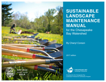
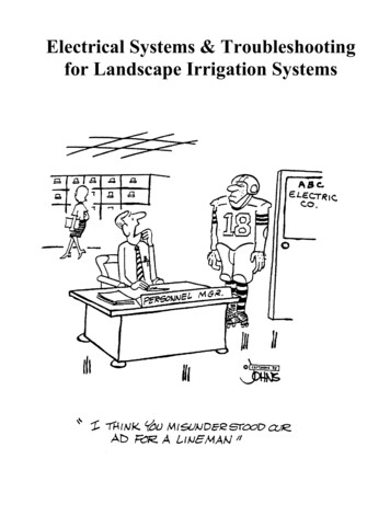
Generating Single Phase Alternating CurrentAlternating Current (AC) flows in a circuit first in one direction and then in the oppositedirection. If you graphed the voltage supplied by a single phase generator on a very fast meter itwould look like this shape below which is called a "sine wave".The voltage increases to a peak value then drops back to zero. At this point the electrons change andflow in the opposite direction. This is not negative voltage, it is just shown as negative to indicatethe electrons are flowing in the opposite direction. The voltage now increases to a peak value in theopposite direction then drops back to zero. This cycle repeats itself 60 times each second for allelectrical systems in North America and 50 times each second in most of Europe and Asia. Thespeed it repeats is called the system frequency and commonly given in units of hertz or cycles persecond.Peak VoltageThe peak voltage is the maximum value the voltage gets to during any part of the cycle and can bepositive or negative. Remember, positive and negative really refer to the direction of current flow.A negative number does not mean that the voltage or current flow are less than zero, only in theopposite direction.Frequency, Cycles/Second, HertzA cycle is one complete repetition of the sine wave pattern. It is produced by one completerevolution (360 degrees) of the generator. In each cycle, their are two peak values (one positive andone negative) and two zero crossing points. This is called the system frequency.RMS VoltageRMS stands for Root Mean Square and is the standard way of measuring and reporting AC voltage.It is the average voltage available between zero crossing points. The RMS voltage is found by13
multiplyingthepeakbythesquareroot of2(approximately1.414).14
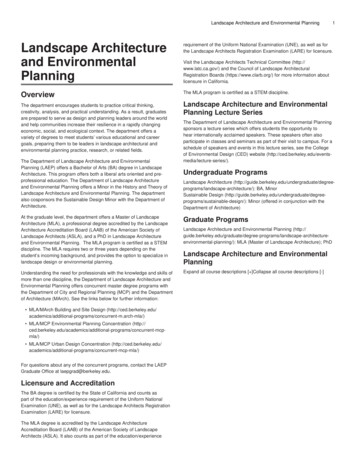
Electrical SafetyHumans respond to electrical current (amps) and NOTvoltage!Current can cause injury or death by:BURNS(Internal or External)PARALYSIS OF THE LUNGS (lackof oxygen)VENTRICULAR FIBRILLATION(restricted flow of blood)15
Typical Human Response Levelsto Electrical Current are:Perception: (1/1000 amp or 1 milliamp)Let Go: (15/1000 amp or 15 milliamps)Burns: (50/1000 amp or 50 milliamps)Fibrillation: (1/10 amp or 100 milliamps)16
Several Ways to Prevent Electrical Shocks1. Don't let your body complete an electrical circuit.2. Make sure your electrical system is correctly grounded.3. Ground electrical equipment and appliances correctly.4. Use "double insulated" portable power tools with non-groundedoutlets.5. Install "GFCI" (Ground Fault Circuit Interrupters) in wet/dampareas.6. Look for the UL label to ensure products have been tested fortheir environment.17
GROUNDINGThis is a large amount of confusion between the terms grounded and grounding.GROUNDEDA grounded conductor is a current carrying circuit conductor intentionally anddirectly connected to earth. It carries current under NORMAL circuit operations. Agrounded conductor limits the potential difference to earth of one of the electricalsystem wires. It is more correctly called a grounded circuit conductor. On mostelectrical systems, the grounded conductor is also the neutral conductor and is morecorrectly referred to as the grounded neutral conductor or just "neutral".GROUNDINGA grounding conductor is a safety wire connected to the metal enclosure of electricalcircuits and equipment. A grounding conductor does NOT carry current underNORMAL equipment operation. A grounding conductor carries current underFAULT conditions on the circuit. It is sometimes referred to as the equipment groundor the case ground. It is not required to make the electrical circuit work but isrequired to make it fail in a safe manner.REMEMBER:Electrical systems are "grounded" by connecting the neutral or grounded wire toearth.Electrical devices are "grounded" by connecting an equipment grounding conductorfrom the service panel to non-current carrying parts of the device.18
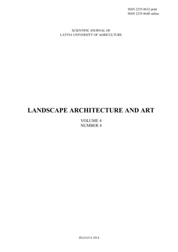
EQUIPMENT GROUNDING WITH GROUND RODS?A 3/4 horsepower, 120 volt motor draws 13.3 amps and is installed 1000 feet from the breaker boxand wired as shown below.Would the 15 amp fuse installed to protect the wires from overloading blow if the motor directlyshort circuited to the metal enclosure?120 volts----------- 12.0 amps of fault current through the ground rod.10 ohmsThe 15 amp fuse will NOT blow even under a complete direct short circuit of the motor!If an equipment grounding conductor was correctly installed from the breaker box to the metalenclosure of the motor, would the 15 amp fuse blow if the motor shorted as indicated above?1000 feet of #12 copper wire 1.59 ohms120 volts---------- 75.5 amps of current through the equipment grounding conductor.1.59 ohmsThe 15 amp fuse WILL blow immediately and de-energize the circuit.19
Power QualityWhat is Power Quality?A term used to describe various types/degrees of disturbances that occur in normal electrical systemsbetween the generation plant and the customer's equipment. Power quality broadly encompasses theentire scope of interaction among electrical supplier, the environment, and the electrical system andequipment energized connected to the system.IEEE (Emerald Book) Power Quality Definition:The concept of powering and grounding electric equipment in a manner that is suitable to theoperation of that equipment.In other words.doing what it takes to keep the electric service to equipment transparent or unnoticed. Power quality is more than delivery of "clean power” from the electric utility that complieswith industry standards. It involves the power and design, selection, and installation of every pieceof hardware and software in the electrical energy system.What is a Power Quality Problem?Any electrical occurrence or disturbance on an electrical system which causes unwanted or results inunsafe operation of equipment. Electrical utilities and their customers have been experiencing agrowing number of problems associated with the apparent quality of electrical power. Power qualityproblems typically cause equipment malfunction, excessive wear or premature failure of electricalequipment, increased costs from downtime, increased maintenance and repair time and expense, andoutside consultant expense.Why Power Quality Problems Now?The quality of power in the past was suitable for most resistance and inductance applications such aslighting, motors, and transistor electronics. New electronic equipment technology and increasingcustomer expectations are changing this situation rapidly. Power quality has been a problem eversince the conception of electricity, but only over the last two decades has it gotten considerableattention.1980's: large numbers of computers & microprocessors in business and homes.1990's: the network revolution and ever increasing equipment capability and speed.Today's high technology electronic environment brings with it the possibility of many new powerquality problems. Ever increasing integrated circuit densities, faster processor speeds, andincreasingly sensitive equipment will undoubtedly mean that power quality must improve.Power quality has become more of a concern because:1. Loads have changed from electro-mechanical to electronic and are more susceptible to powerproblems. In addition, the sensitivity of electronic loads has increased over the last 10-15 years.20
2. Our perceptions and expectations “have changed”. More and more jobs utilize electronicequipment and we used to expect and tolerate computer problems “every so often”.Example: Computers lock up every so often and the user has no clue why. Users don’t tolerate asmany problems as they once did.500 employees and 10 computers:If each locks up once a day, who cares.not that many people were affected.500 employees and 500 computers:If each locks up once a day, everyone is affected, especially if its mostly at the same time. Add anetwork and if every machine on the network locks up, more people are affected more times.3. Widespread use of electronic (non-linear) devices produce power quality problems of their ownon the system. Utility systems were designed assuming loads were electromechanical and thatvoltage and current supplies would always be sine waves. Electronic devices produce harmonicdistortion and the proliferation of electronics challenges the sine wave assumption. Many electronicdevices are susceptible to power quality problems AND a source of power quality problems.Power Quality Studies:Electric Utilities are typically blamed for having “dirty power” or causing power “spikes”, “surges”or “glitches”. On the average, about 8 out of 10 power quality problems are caused from within thecustomer's facility. (This still means 1 out of 5 are caused by something outside the facility). Attimes, power quality is confusing because historically, there has been a lack of common definitionsand terms.TYPES OF DISTURBANCESThere are several different types of power disturbances and grouping the disturbances into generalcategories makes for more effective analysis. IEEE Standard 1159-1995: IEEE RecommendedPractice for Monitoring Electrical Power Quality defines six basic categories of disturbances:InterruptionsShort Duration Voltage Variations (Sags & Swells)Long Duration Voltage Variations (Undervoltages & Overvoltages)TransientsHarmonic DistortionFrequency VariationsThese six disturbances can generally be further subdivided into different types of sub-categoriesdepending on the magnitude of change to the supply voltage and/or length of duration of the event.Instantaneous Event:Momentary Event:Temporary Event:Long Term Event:duration less than ½ cycle. (1/120th second)duration between ½ cycle and 3 seconds.duration between 3 seconds and 1 minute.durations longer than 1 minute in length.21
InterruptionsInterruptions are defined as events where supply voltage falls below 10% of the nominal circuitvoltage. Utilities have historically used the term “outage” to describe events resulting in the absenceof voltage over significant time periods. An interruption in the context of power quality has beendefined to be more specific regarding the absence of voltage for specific time periods, usually muchshorter than what has been historically defined as an “outage”. Long term interruptions may qualifyas “outages” for utility reporting purposes, however, many short term interruptions do not eventhough they may have detrimental affects on equipment operation.Short Duration Voltage VariationsShort duration voltage variations are defined as voltage variations outside the normal supply limitslasting less than 1 minute in time. Lower than normal voltages are called “sags” and higher thannormal voltages are called “swells”. Other than harmonic distortion, voltage sags are probably oneof the most “discussed” power quality problems of the day.Sags:Temporary voltage drops lasting less than 1 minute and having a magnitude between 10 and 90% ofthe nominal supply voltage.Swells:Temporary voltage rises lasting less than 1 minute and having a magnitude between 110 and 180%of the nominal supply voltage. The slang term “spike” should be avoided. Sags and swellssometimes precede interruptions.Long Duration Voltage Variations:Variations in the RMS supply voltage outside normal limits lasting for longer than one minute intime. Long duration voltage variations include both over or under voltages outside the normal RMSsupply voltage limits commonly referred to as Over-voltages and Under-voltages and not qualifyingas interruptions.Undervoltages:Voltage drops lasting longer than 1 minute and having a magnitude between 10 and 90% of thenominal RMS supply voltage. The term brownout is sometimes used to describe sustained periodsof undervoltage. Because there is no formal definition for the term brownout and it is not as clear asthe term undervoltage, the term brownout should be avoided.Overvoltages:Voltage rises lasting longer than 1 minute and having a magnitude greater than 110 percent of thenominal RMS supply voltage. Overvoltages result because the system is either too weak for thedesired voltage regulation or voltage controls are inadequate.22
Voltage Transients:Historically, the term transient has been used in power system analysis to note an undesirable butmomentary event. Unfortunately, this definition can be used to describe just about anything unusualthat happens on a power system. Many misunderstandings about power quality come from poorterminology used to describe transient disturbances such as bump, glitch, surge, and spike.A voltage transient is a sub-cycle (less than 1 cycle) disturbance in the RMS voltage AC waveformthat is evidenced by a sharp brief discontinuity of the waveform for an extremely short time period,usually measured in microseconds.Transients have definable beginnings and ends and after the transient has moved through the system,the voltage returns to normal. Transients may be in either polarity, and may be additive orsubtractive from the normal waveform and can occur on the phase, neutral or grounding conductors.Transients can occur at a single time or at repetitive intervals. Repetitive disturbances can occursynchronously throughout a single cycle or regularly in multiple cycles.They are generally not conducted far from the source of where they enter the power system, althoughthey may, in some cases, be conducted for quite some distance along utility lines.Frequency VariationsOn modern interconnected power systems sign
Electrical Power Electrical power is a measure of the rate of work an electric current can accomplish. Think of this as how fast electrical energy is being converted into some other form of energy like light or rotating mechanical energy. In general, the higher the power consumption of a d