Transcription
S206E057 – Spring 2021S206E057 -- Lecture 2, 5/11/2021, Rhinoceros – an IntroductionCopyright 2021, Chiu-Shui Chan. All Rights Reserved.Parametric modeling: A parametric modelling method is a family of “distributions” that can be described using a finitenumber of parameters. The notion of “distribution” is the action of sharing something out among a number of recipients. Theconcepts of parametric modeling will be introduced in this course through three modules; each consists of roughly 7 to 10lectures and one work session for exercise. Each module will have its own assignment to complete.1. Rhinoceros modeling (2-10)a. Setup – unit and scaleb. Drawing: 2D Geometryc. Surface and 3D geometric modelingd. Site modelinge. Organic form modelingf. Building form creations2. Grasshopper (11-18)a. System setupb. Concepts and implementationsc. Examples of architectural form generation3. Python (19-24)a. System setupb. Examples of architectural form executionRhinoceros Systems:In May 1992, first prototype of Rhino was developed in AutoCAD to generate NURBs’ geometries. It was a class projectdone by Michael Gibson in November 1992, presented in March 1993 and named Sculptura. In November 1993, Sculpturawas nicknamed Rhinoceros and its first version was publically released in April 1994. Current version is Rhino 6.In fact, Rhino focuses on the Nurbs Modeling. Nurbs stand for Non-Uniform Rational B-Splines, which means that smoothsurfaces can be created through mathematical formulas. What this means to us is that complex smooth forms can becreated that are highly adjustable and editable for designers. In traditional computer modelers, surfaces are defined by aseries of flat planes joined together to create a facetted surface. Nurbs modelers, however, allow us to create smoothcomplex surfaces by simply defining a couple of points that can then be manipulated. Thus, when it comes to simplemodeling, Rhino is easy to use and a highly intuitive modeler.Who uses Rhino? Industrial designers, architects, vehicle designers, jewelry designers, and sculptors use Rhino. Others infilm and TV effects, game design, and character design would use 3D Studio MAX, Maya, or MODO instead of Rhino. Hereis the introduction of Rhino in 2D as a fresh beginning for modeling purposes. Hopefully, after this lecture, you will becompetent to start working on your Rhino modeling.The software could be downloaded free for trials at: http://www.rhino3d.com/download. The free trial version doesn’t havecopy & paste functions available for use to prevent copying models from other projects. But, the rest functions are the same.It also has 25 limited times to save files. This means that at the end of 25th time of saving Rhino files, the system willautomatically stop working as for trial version. Thus, it is good to use the free trial version in your machine for learningwithout saving the file, and use Lab machines for completing assignments. The student version enjoys a big studentdiscount (around 100 in US). Tutorial materials of Rhino training could also be found at: http://www.rhino3d.com/tutorials.Hardware:1. Recommended: HP Precision Line (hardware) is designed for rendering and modeling works.2. For the operating system, use 64 bit and minimum of 8Gigs of RAM and 16Gigs Ram for efficient rendering.Page 1 (5/11/2021)
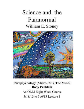
S206E057 – Spring 20213. For video cards, the Nvidia QUADRO K lines are recommended, see the page athttp://www.nvidia.com/object/quadro.html. Such K lines of video cards will drive at least two monitors.4. For the graphic drive, use open GL which is the workstation class 3D accelerator and it is better than the competingsystem of DirectX. DirectX is typically meant for games.General introduction of system setup:1. Initiate the Rhino system. When it starts, the first window provides template selections to use. This window willdisappear after a short period without receiving users’ selection.2. The template selection could also be done through the “File menu New” function. New Select the template of“Small Objects – Inches”, which will have 0.001 units of accuracy tolerance for the new environment. This settinggets the unit of inches with three decimal places of accuracy as for tolerance. If your Rhino model is a buildingcomplex, then choose “Large Objects – Inches”. In this example – the absolute tolerance will be 0.01in. We couldchange the tolerance value to 0.001 by changing the value in Tool Units Absolute tolerance. If you are in theRhinoceros environment and want to open a new one, then alternatively go to Help menu About Rhinoceros in the window, select the “New folder” to find template selections.3. Rhino has a typical Modeling interface. By default, it is composed of four view points and a tool palette on the left.At the bottom are the ortho and object snap controls. At the top are the Pan and Zoom Controls, as well as the toolcommand prompt.Command PromptView ControlsRendering ControlsAssist/Properties PalletThe Modeling WindowsThe Modeling Tool PalletSnap Etc. ControlsPage 2 (5/11/2021)
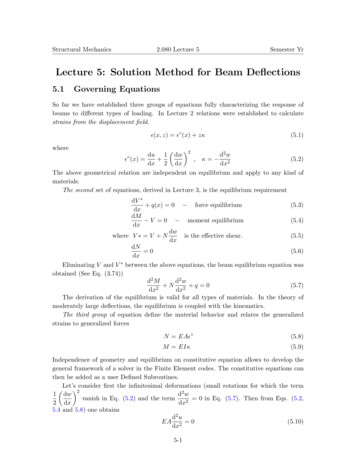
S206E057 – Spring 2021Introduction of setting up grids and units for accurate modeling:Click on File Properties to open the settings window, which is the same as Tools OptionsClick on the units Tab Model and select eitherMillimeter or Inches. Match your unit with theDistance Display.Click on the Grid Tab and set a grid snap and gridspacing. Note: if you are using Feet and inches, a gridunit of 12 (or 8) is best; and 10 is best for metric.Units TabUnits SettingGrid TabMajor Grid LinesMatch your unitsSnap SpacingDisplay SettingIntroduction of Snap, Ortho, Planar, OSnap, Record History, and S-Track:The bottom of the Rhino interface has a number of drawing aids. These aids allow us to lock lines and Snap as needed.Project: Will project line snapped to geometry onto the ground plane, useful for creatingPlan outlines.Diable: Disable the O-Snap functions.Record History: Allows you to link lines to surfaces. If you change the line, itwill update the suface (kind of works).S-Track: Allows you to snap projection line from multiple types of geometry.Osnap: (Object Snap) Activates the snap menu. Will snap lines to geometry asyou draw.Planar: Keeps curves in a set plane as you draw from on view to another.Ortho: Locks lines to 90 Deg. Hit F8 to toggle or hold down shift key while youdraw.Snap: Toggles the grid snap on or off that we just set.The folder area, below the command line area, has categories of functions for 2D drawing, 3D form generation and editing.Select one folder, its associated tool icons will show on the tool bar button panel area. Other than visible tools displayed onthe folder, there are other special tool palettes that could be found from the “option icon” at the very right of the “folder label”area. See the second bottom photo on the following page.Page 3 (5/11/2021)
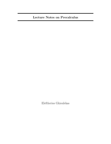
S206E057 – Spring 2021Example of major Tool Palettes:Selection Tool: Used to select and move objectsDraws Points: Used to place single points. This can be used with rail sweeps.Draws Lines and Curves: Used to construct splines for surface and object generation. See below.Draws Circles and Ellipses: Used to construct closed curves.Draws arc’s.Draws Rectangles.Draws Polygons.Fillet Tools: See Below. Hold down mouse for more options.Surface Tools: See Below. Hold down mouse for more options.Advanced Surface Tools: See Below. Hold down mouse for more options.Solid Tools: See Below. Hold down mouse for more options.Boolean Tools: See Below. Hold down mouse for more options.Curve from Object Tools: See Below. Hold down mouse for more options.Mesh Tools: See below. Hold down mouse for more options.Join Tool: Used to join together two surfaces.Explode Tool: Used to break apart joined surfaces.Trim Tool: Used to cut a surface with another object.Slit Tool: Used to cut a surface with a cutting object.Group and ungroup tools.Control points on and off toggle tools.Point editing controls: see below. Hold mouse down for more options.Place text tool.Transform tools: Hold mouse down for more options.Copy Rotate and Scale Tools.Analysis Surfaces Tools.Most of the tools are accessed from the menu items. There are specific Rhino tools that are not in the menu nor the tool barfolder area, but could be found/show/hide in the tool bar option – indicated as the blue color icon in the following figure.Curve (Curve) Tools are used to create curves.Curve (Curves) Tools are used to adjust and fixexisting curves. These include Fillets, Chamfers,Offsets, Fix Points, Simplify and Rebuilding Curves.Page 4 (5/11/2021)
S206E057 – Spring 2021Surface creation Tools: This palette is used to generate surfaces from Points and Curves,Lofts, Surface from Curve Network, Sweep along one and two rails, Revolve, Patch, andDrape Functions.Surface editing tools: These are used to edit, adjust, fix and rebuild surfaces.Solid Creation Tools Pallet: This is a typical pallet of object primitives that can be created.Solid Editing Tools: These includes difference, union, intersection. As well as fillet, capholes, and extract surfaces.Curve From Object Palette: This is used to generate curves from objects that then can beused to generate more surfaces. You can also generate a series of contours from anobject, section curves, etc.Mesh Tool Palette: This is used to extract mesh surfaces and objects from NURBssurfaces. This is useful for exporting into other programs. You can also create direct meshobjects without creating a NURBs object first.Introduction on setting up Rhino model scene:1. Define the units, tolerance, and AutoSave interval time within the Tools Options, or type “units”1. Units is used to define system units of feet-and-inches, metric system, or decimal system for the modelconstruction standard as well as for screen display. Assign the model units to the desired unit system, i.e.,Model Units Inches, change Absolute tolerance to 0.001. Distance display Feet & Inches,Page 5 (5/11/2021)
S206E057 – Spring 2021Layout Units change to Inches.2. Absolute tolerance (up to 0.001) will provide more accurate detail to display the computed or calculatedcurvature of curved surfaces. If the project expects you to have extremely intricate detail, then increasethe tolerance by a factor of ten. Yet, use the value of 0.001 to keep accurate curved surfaces.Concept of Absolute Tolerance value:The absolute tolerance value will maintain the geometric results of surfaces. Whatever the changes itmade, the resulting geometry will not be modified. In other words, a changed tolerance only affectsobjects created from that point forward; and it doesn’t change old objects at all. In that case, you mighthave some problems on having different tolerances on different geometry. When combining thesegeometries together, serious modeling problems will occur. So, please be aware of that.Even though you can change the tolerance any time in Rhino, it's not a good solution to make a change inthe middle of modeling, it can easily make problems worse. A changed tolerance only affects objectscreated from that point forward. It doesn't change older objects at all. In that case, you have a worseproblem of different tolerances on different pieces of geometry. So, don’t change the level of tolerancefrom time to time. Keep the value consistent.3. Files selection Click the Autosave to define the interval time for Autosave.2. When we work on modeling, we might want to redefine the selection color before we start. So, change colors ofthe followings for legibility.a. Tool menu Options (or just type options on the commend line) Appearance Color Change thebackground color from grey to white, and change “Interface Objects” Feedback, Tracking lines, andCrosshair color to red color. Of course, we could use default colors without making changes.(Note: it is convenient to define the major grid line and minor grid line for modeling and drawing aids. Thenotions are to assign a particular color for the major line by clicking the Major grid line box and change thecolor to dark blue and Minor Line to light grey. Then, all the grid lines will show in dark blue color on allviewports, which is easy for finding the needed position or location in space.)b. Modeling Aides Nudge Nudge key to Arrow keys (use alt arrow keys for view manipulation.c. Smart Track / Appearance area, change Line color and Point color to red OK (These settings will besaved individually for each machine, but, not for the Lab machines.)3. Set up Grid system for modeling:Rhino uses a fixed Cartesian coordinate system called the world coordinate system (WCS), based on three axes ofx, y, and z axes that define locations in three-dimensional space. Each viewport has a construction plane thatdefines coordinates for that viewport. The grid is an array of lines lying on a portion of the construction plane in theviewport. The construction plane is infinite. The grid covers only a specified portion of it.The Grid commend defines the grid system shown on the drawing canvas which has the following properties ofGrid Snapping Interval, Minor Grid Line Spacing, Major Line Interval and On & Off. Grid system serves as adrawing aid. The best way to define Grid, globally, is in Options Grid window area, which assigns grid for allviewports. But, for convenient, the Grid function in command line controls individual view port. Relatedsubfunctions have the following related parameters.--Grid Snap is also controlled by F9 key, and the first box located next to the Ortho tool in the bottom of drawingstatus areas.--Grid line count: 200 (The maximum size of the grid is 100,000 lines.)Page 6 (5/11/2021)
S206E057 – Spring 2021--Minor grid lines every 12 inches--Major lines every 10 minor lines--Way to turn off grid lines: Grid click the ShowGrid to turn it to No.(Note: Rhino has cplane command to define/set the origin and orientation of the construction plane in the activeviewport. We could use View menu Set Cplane function “To Object” subfunction to define the constructionplane, and use “4view” to go back to world view.)4. After the units, grid line count of 400 (for this lab exercise) along each side of the axis of the view port, the absolutetolerance of 0.001, and the color representations were all well-defined, these settings will serve as our modelingenvironment. Thus, we customized an ideal modeling environment for our own convention, which could be usedconstantly in future modeling tasks. Such a customized environment could be saved in Rhino data base. File Save As Template In this example, it will be saved with the name of “CSC Large Object – Inches” as a customized template. Whenever this template is opened, the same setting will be applied for convenience. The following notions ofinterface are flexible settings applied during the modeling sequences and which are not limited to any templatesettings.5. Rhino Interface:a. Window frame: double click the window label change into a single window or four windows.b. Shade mode: (1) Display tool bar, wireframe, shaded mode; (2) use layer color for objects; (3) Rhinorendering will use texture material for rendering, ghosted, X-rayed, pen, etc. The rendering could also becustomized. Most of times, the ghosted mode is the most popularly applied display mode.c. Right-click the mouse will get to “orbit” mode when in 3D, hold “shift” and right-click to pen in 3Dperspective view port.d. Gumball is a unique tool for changing position, dimension, and rotation. If you want to use keyboard input,then, just select and click on the end square of the axis and type in the attributes in the input box.6. Commands, Tools, and input mechanisms: Keyboard input: line to draw a single line, Keyboard input: lines to draw continuous lines, there are a number of options for drawing special lines. Or, in Line Tool bar, drag the lower triangle in the lower right corner of the tool box to find the first tool ofline in the selection group, which is to draw a single line tool. Or, in Menu area Curve menu Line Single Line, Curve Line Line segments for multi-lines. Or, in the Options (located in the very right end of the “tool folders” area with the small utility sign on it) Show Toolbar Select Lines, it will put the Line Tool Tag onto the screen. If it hasn’t shown up, then dothe following:Options Show or Hide Tabs and click the Line (which label is shown in dark color) to show it.Page 7 (5/11/2021)
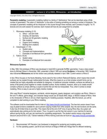
S206E057 – Spring 2021First exercise on two-dimensional drawing:1. Drawing area: Define a window (or rectangle) shape representing the working (or drawing) area. This shape wouldbe the boundary signifying the size of the canvas or the model to be constructed. In architectural design, it is theoutline of the building site. This is the defined boundary of the drawing or model that you won’t be confused by theunit.2. Rhino has four entities of point, curve, surface, solid, plus special case. The point entity is only used as areference or a marker for modeling. Other functions could be found on the menu area. Each has its own characterand function groups.3. Difference between polyline and line: Menu Curve Line to draw a single line.Menu Curve Polyline Polyline, draw the same shape with polygon function. The result will be thesame group of lines.(Or, left click the line tool to activate the “Polyline Tool”, then we could start drawing a series of lines (evenacross the viewport on front, right, or perspective viewports to generate 3D shapes.) Right click tocomplete the drawing or click the starting point to complete an enclosed shape. The result would be oneline with several segments.Menu Curve Line Line Segments to continue the line drawing connecting from the last point of thelast line and to complete the shape. The results will be as jointed segments of lines.(Or, right click on the “Line Tool” selection to activate the “Line Segment” tool. We could repeat the sameaction to complete a shape. But, the lines are separate segments, instead of an integrated line segments.Each segment could be moved or erased.)4. Other line drawing mode: Draw BothSides lines: it is not available from menu selection. This means that it is not all of thecommands would be shown from all input mechanisms.Interesting function: Line perpendicular from curves:5. Edit the drawing: Select the shape and turn on the control points (“Points On” and “Points Off”), then move the control pointto modify the geometry.6. Create a simple line drawing, as the prototype, in this exercise as shown on the left image.Then apply fillet, chamfer, join, offset, 2D rotate with “copy on” to create the drawing shown on the right side ofthe image below. The rotation angles could apply the value of 36, 72, 108, 144, 180, 216, 252, 288, and 324 to geta perfect composition of ten pieces of the shape.Page 8 (5/11/2021)
S206E057 – Spring 20217. Further use of copy function to create a similar image as the one shown in the lower left with different location inspace.8. Use array and cylinder functions to create the model in the lower right, which could be interpreted as column series.9. Rhino files will be saved with “3dm” file extension format. (The model could also be saved as: (1) Autocad drawingand ported into ACAD for advanced level of graphic processing, or (2) as Google Earth model for Google Earth.)10. Interface with other systems:a. 3D Max files could be loaded to Rhino through obj file format. But the process is a bit of complicate.b. Other 3D modeler files or models could also be loaded to Rhino. You could do some research on thisfeature.c. Result of this exercise: type “ViewCaptureToFile” function to save the viewport screen image to a JPEGfile, name it “FirstName LastName.JPG file, named it to the Lab Exercise” folder in the “my.files” serverto complete this short and simple exercise.11. Project hints:Examples of 3D Rhino models done by Rhino functions.3D Rhino building complex projects shown in the following were done by Rhino functions aided by Grasshopperalgorithms implemented in Rhino.Page 9 (5/11/2021)
S206E057 – Spring 2021System update for Rhino 7:Rhino 7, an update version of Rhino 6, is in the developing stage since 2018. A new test version called Rhino WIP7.0.20071 (work-in-progress) for Windows and Mac is available in March 2020. In this version, there are new functionsadded, updates installed, and bugs fixed (see the page: le-now/53374/77).Especially, the new menu item of “SubD”, relating to the surface editing, is a good tool for managing surfaces. This SubDand related functions plus their applications could be explored from the page: no-7/.Page 10 (5/11/2021)
Rhinoceros environment and want to open a new one, then alternatively go to Help menu About Rhinoceros in the window, select the “ New folder” to find template selections. 3. Rhino has a typical Modeling interface. By default, it is composed of four view points and a tool palette on