Transcription
Air Core and Magnetic CoreTransformers for IsolatedPower ConversionBAOXING CHEN10/03/2016Analog ot for external distribution
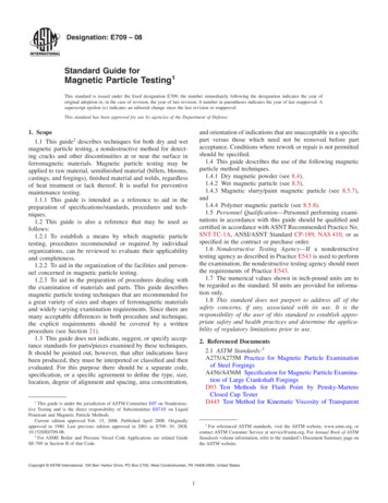
Micro-Transformers Replace Discrete Transformers, Diodes &Opto-couplersHigh speed, low power and integrationConventional, Discrete Solution½ W Isolated Power & 4High Speed Data Channels High-freq energy conversionlow-freq energy regulationAnalog Devices Confidential Information
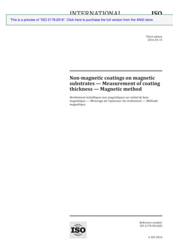
Micro-Transformers Enable Signal and Power Isolation: 1.8Billion Micro-Transformers Have Been ShippedCumulative Channels of iCoupler Isolation [Billions]ADuM4160USBADuM1220½ BridgeGate DriverADuM140x4 Channels inOne x5 kV rmsIsolationADM248xRS-485 ADM2582RS-485 withisoPowerADuM540xisoPower ADuM120x2 Channelsin NarrowSO-8AD7400ƩΔ ADCADuM125xI2CADuM4135IGBT Gate DriverADuM124x/144xUltra LowPower IsolatorADE791xIsolated MeteringAFEADM305xADuM5230½ BridgeDriver with ADuM347x M3251ERS-232ADuM14xRobustQuad DataADN4651600MbpsIsolated LVDSADuM74101 kV rmsAnalog Devices Confidential Information3
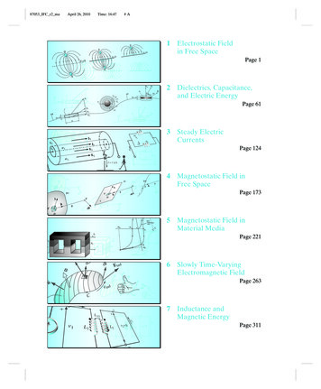
Power Transformer Radiation Minimized Through Anti-PhaseCenter Tape But PCB Radiation Needs MitigationChipOverallEmissionPCBNo PCB SuppressiontechniquesPCB Suppressiontechniques360MHz180MHz4Analog Devices Confidential Information
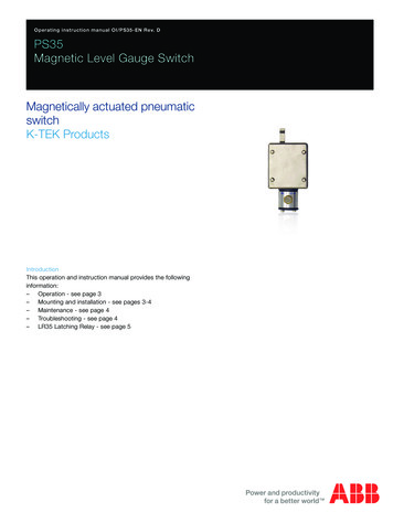
Integrated Magnetics Bridge The Gap Between Air-Core andDiscrete TransformersInductance (Size)10mH1 I fL70 80%1mHDiscreteIntegratedMagnetic Core0.1mH50 60%30 40%10nHEfficiencyEMI z1GHzSwitching FrequencyAnalog Devices Confidential Information5
Inductor Configurations: Pot-Core vs SolenoidREF1*Tyndall Cian O’Mathuna Group Magnetic layers enclosing spirals Minimum flex leakage (radiation) Complex core structure Difficulty in domain alignment control Significant core loss*Stanford S Wang Group Windings enclosing magnetic core Via complexity Flux leakage (radiation concern) Simple core structure Higher permeability Easy domain alignment Flux parallel to surfaceAnalog Devices Confidential Information6
Transformer Configurations For Achieving IsolationTop ViewInterleaved Primary and Secondaryfor Best Mutual Coupling*Tyndall Cian O’Mathuna GroupSide by Side or StackedAnalog Approach 5kVrmsAnalog Devices ConfidentialInformation Isolation
Converter Architectures Suitable For IntegrationFlyback Simple with fewest components No output filtering inductor Load dependent saturation current Limited power densityLLC converter High efficiency (ZVS) Load current provided by resonant current High power density Need Lr or use leakage inductanceAnalog Devices Confidential Information8
Equations for Magnetic Solenoid InductorsL m 0 m r N 2 wt mlwc wC 2 N 0 rti2 Nw Rdc wctc m 0 m r Nt m wc t cQ R2l LI satBsatl mNE 21 Li1 tm Bsat 2 wl2m LargeHigh Qwc Coil Width Large tc ShortLength l wc! Higher2Coil ThicknessPermeability mr Large tmThicker tm Higher Energy DensityAnalog Devices Confidential Information
Core Lamination Reduces Loss TangentBulk Permalloy (NiFe) Laminated Permalloy (NiFe) Stable soft magnetic material2 um NiFeHigh quality core with multiple layers of NiFe20x (NiFe /AlN)Dedicated magnetic material depositionsystem (Oerlikon EVOII)ParameterMeasuredResultThickness micronsSaturation1.1TRelativePermeability 1000CoercivityLow 0.1 OeCurie Temp570ºCPermeability (-) 1200ur' bulkur'' bulkur' laminatedur'' laminated10008006004002000110Analog Devices Confidential Information100100010000Frequency (MHz)
Transformer On-Wafer Characterization[S][Z]4 Port NetworkAnalyzerTransformer Open DieGSG RF probeAnalog Devices Confidential Information
Transformer Modeling with HFSS3D; Full wave EMsimulator; Finite elementmethodtetrahedralzy(not in scale)xHFSSThickness(µm)MaterialConductivity (S/m)Winding4Gold3.5875e7Core2NiFeNiFe: 1.4e7Analog Devices Confidential Information
2mm Core Transformer Characteristics – Simulation & Measurement4.5580nH0.93Analog Devices13 Confidential Information
-1250-1500-1750-2000Q (-)Improved Quality Factor for 4mm Thick CoreMaterial 1Material 2-50-40-30-20-10 0 10 20 30 40 50Oersteds 876543210Material 1Material 20.11.010.04um amorphous magnetic core Qmax 7.5 – close to target Q 8,Major core stability improvement.Analog Devices Confidential Information100.01,000.0Freq (MHz)
Winding Thickness Improvement Device FEM models fmr m0Skin depth for Au @ 20 MHz:17.5 umDCR reduction effect:Model optionQ max (-)2x6 um Au (default)7.702x8 um Au8.852x10 um Au9.71 Model:Increased thickness ofAu metallization by 2 um willdeliver Q 8Analog Devices Confidential Information
Effect of DC Bias and Large AC Signal on RF PerformanceNiFeMaterial 1Analog Devices Confidential Information
Summary MagneticCore Has the Potential to Improve Converter Efficiency andReduce EMI for Integrated DC/DC Converters IntertwinedSolenoid Transformers Have Been Modeled & Characterizedand Have Excellent Magnetic Coupling 2mmMultilayer Core Lead to a Q of 5 at 20MHz For the IntertwinedTransformers 4mmMultilayer Core With 8mm Thick Winding Achieved Q 10 Effectof DC Bias and Large Signal on Transformer Performance HaveBeen Characterized DC/DCConverter Passed Class B EMI and Achieved 46% Efficiency at200mWAcknowledgements: Contributions from iCoupler group & ADLKFAB ipassive team in ADIAnalog Devices Confidential Information
Air-Core Integrated Magnetics Bridge The Gap Between Air-Core and Discrete Transformers 5 10mH 0.1mH 10nH 1nH 100KHz 1MHz 100MHz 1GHz 30 40% 70 80% Switching Frequency (Size) 10MHz Integrated Magnetic Core