Transcription
LibreCADforReal Dummiesa free option forComputer Aided DesignJohnny Heikell2019Based on LC version 2.2.0rc1Released under Creative CommonsNo Commercial, Share Alike
Page intentionally blank
About this tutorialThis tutorial was born out of my attempts to learn – sweating while learning – LibreCADfor domestic purposes. LibreCAD does not have a decent user’s manual and the brieftutorials that exist are partly obsolete – geeks do not like to write manuals. The remaininginformation about LibreCAD is scattered around various web pages, user discussions,and on YouTube. I got a feeling that I would not learn LibreCAD unless I collected andorganized basic information in a better way. I am also old-fashioned and prefer a tutorialas a hard copy to skim, laying on the table beside the laptop.The text is written on LibreOffice Writer and I only talk about Windows and Linuxbecause I have no experience with Apple products. No Mac, no idiotPhone, no nothing.LibreOffice gave problems that may show up although I try to hide the mess. Someproblems could be solved by exporting the document as PDF and using LibO Draw asPDF editor. Scribus https://www.scribus.net/ would nevertheless have been a bettertool for this job. In most cases the screenshots are edited with GIMPAnother IT problem came when I tried to share information on this tutorial onLibreCAD’s Forum. I tried to register as Forum contributor, but after CAPTCHA finallyaccepted that I am not a robot there was no instructions on how to finalize registration.Security is good, too much security – no good.According to a 2018 decision by the European Court of Justice, borrowing images fromthe web – even for non-commercial and educational use – is completely forbiddenwithout consent by the creator/copyright holder. To the best of my understanding thereare no restrictions on the few that I have borrowed (all from Wikipedia except ascreenshot and one image at the very end from http://www.freedwg.eu/ ). Imagescreated by me are in the public domain.Why the title “LibreCAD for Real Dummies?” Elementary: I consider myself aLibreCAD dummy. Whoever can learn something from me must be a Real Dummy.I share the tutorial with no guarantee for its correctness – it is after all a diary born whilelearning. Some of my LibreCAD drawing attempts are clumsy, some are better. I firstused LC 2.1.3, then changed to 2.2.0rc1 and that can be a source of inconsistencies. Also,nobody else has checked the text so I’m sure there are both typos and other errors.Feedback is welcome – perhaps I’ll update this text – until the end of this year atlibrecad * heikell.fi, where * stands for the at sign. I read what drops in but may nothave time to answer and will close the mailbox sooner if spam starts to accumulate.Johnny HeikellEspoo in January 2019i
Page intentionally blankii
Table of Contents1 CAD basics.1History.1Basic CAD concepts.2Entities.2Layers.2Blocks.2Coordinate Systems.3Dimensions.3Scales.4.dxf and .dwg file formats.4Axonometric projection.4Multiview projection.5Linear projection.62 Introduction to LibreCAD.7FAQ.7What is LibreCAD?.7Who are the competitors?.7Why is LibreCAD used?.8How can you start using LibreCAD?.8Who is/are behind LibreCAD?.8Are there any problems?.9Where can you find help?.9What can you do to help?.11Getting familiar with the User Interface.12LibreCAD GUI toolsets.12Drawing Area.13Layer List.13Command Line.15Control commands.16Block List.20Menu Bar.20Toolbar.21Layer Selection.22Widgets Bar.22Mouse actions, zooming and panning.24Pen Wizard.25Scaling.26Blocks.26Splines.27Trimming and Lengthening.27Shortcuts.28Room for tool improvements.28Interacting with LibreCAD.29The coordinate system in LibreCAD.29The orthogonal case.29The isometric case.30iii
Preparing for work.31Setting units.31Defining attributes for the current drawing.32Changing the type of dimensions.33Widget & Device Options.34Using the Construction Layer.35Saving drawings.35Printing drawings.363 Exercises.39Exercise #1, A4 drawing template.39Preparations.39Draw the border.40Draw the title block.41Add text to the title block.42Printing the template.44Exercise #2, cut cone with thread.45Preparations.45Working with the Construction Layer.46Draw the outer edges.48Adding details.49Dimensions.51Changing scale from 1:1 to 2:1.52Completing the Title bar.54Summary of observations form Exercise #2.55Speeding up: Copy-pasting with the Parallel button.56Exercise #3, 3D object without isometric projection.57Preparations.57Draw outer edges.58Draw edges for the hole.58Cut and hatches.59The question of dimensions.60Printing.61Discussion.61Exercise #4, rack in isometric projection.62Preparations I: Scaling up the Template.62Preparations II: Layers and Preferences.62Drawing outer edges.63Comments.67Exercise #5, flange with holes.68Create a block.68Add the block to A4 Portrait.69Preparations.69Drawing edges.70Exercise #6, forgetting the document size.74The drawing.74Printing.75Discussion.784 Additional tips.79Miscellaneous tips.79Rounding corners.79Lengthening a line.79Add center points.80Linear projections with LibreCAD.80iv
Tab Mode & copying into another document.81Create a fan of lines.81Mirror objects.82Isometric hole.82Creating semi-circles and arcs.83Lost widget.83Grid settings.84Stretch.84Drag-and-drop widgets.84Scale of an imported block.85Remember to zoom and measure.85Dimension problem.85Exploding a rectangle.86Lockup with leaders.86Modifying text.86Keep an eye on the Tool Options Bar.86Import-export.87Export.87Import.87Importing a DWG drawing.88Appendix A.89v
Page intentionally blankvi
1 CAD basicsThis chapter gives a short summary of basic concepts in CAD. You canjump over it if the definitions feel boring and return later for reference.Everything will be discussed later – or so I hope.But let’s start with a nugget of history.HistoryTechnical and architectural drawing upto the 1970s-90s timeframe was donein the traditional way, with pencil andink on paper using a drafting table.Since the turn of the century even thesmallest engineering offices have usedCAD. Today even hobbyists like mehave access to them.In 1957 Patrick Hanratty at GEdeveloped PRONTO (Program forNumerical Tooling Operations), thefirst commercial CNC (ComputerNumerical Control) programmingsystem. Five years later, Sutherlandpresented his PhD thesis at MIT titledArchitect at his drawing table in“Sketchpad, A Man-Machine1893 [Public domain]Graphical Communication System.”Among its features was the first GUIusing a light pen to manipulate objects displayed on a CRT (Cathode RayTube). Hanratty has since been called “The Father of CAD.”CAD software suppliers that are major operators in 2018, emerged in theearly 1980s. Examples are Dassault Systèms that today is best known forDraftSight, and AutoDesk with AutoCAD.AutoCAD marked a huge milestone in the evolution of CAD. Itsdevelopers set out to deliver 80% of the functionality of the other CADprograms of the day, for 20% of their cost. From then on, increasinglyadvanced 2D (Two-Dimensional) drafting and engineering functionalitybecame more affordable.AutoCAD was revolutionary in its early days. Today it is considered arather expensive tool with strong competitors, both lower-cost and freealternatives. Many regard AutoCAD the best CAD solution, but the smartquestion to ask is: “Which solution satisfies our needs?” Don’t pay forsomething you don’t need.1
J. Heikell: LibreCAD for Real DummiesLibreCAD began its life as a fork to QCad and was first given the nameCADuntu. The new name LibreCAD has led to suggestions it should beadded to the LibreOffice package.Basic CAD conceptsEntitiesThe term entity refers to a graphicalobject (“widget”) in a CAD system.Typical entities, supported by mostCAD systems, are: pointslinesrectangles andcircular and elliptical arcsMore complex entities includepolylines, texts, dimensions, hatches(closely spaced parallel lines) andsplines (curves that connect two ormore specific points).Spline [JH]LayersA basic concept in computer aided drafting is the use of layers toorganize a drawing. Every entity in a drawing is on exactly one layer anda layer can contain numerous entities.Typically entities with a common “function” or common attributes areput on the same layer. For instance, you might want to put all axes in adrawing on a layer named axes.Layers can have their own attributes (color, line width, line style etc.).Each entity can have its own attributes or have its attributes defined bythe layer it is placed on. In the latter case you can change e.g. the color ofall the entities on the layer by setting the color (red for instance) for thelayer in case.BlocksA block is a group of entities, similar to what you create with theGroup Ungroup functions in LibO Impress and PowerPoint. Blocks canbe inserted into the same drawing more than once with differentattributes, at different locations, and with different scale and rotationangles. Such a block is usually called an insert.Inserts have attributes just like entities and layers. An entity that is part ofan insert can have its own attributes or share the attributes of the insert.Once created, inserts are still linked to the block they represent. Thepower of inserts is that you can modify the block once and all inserts willbe updated accordingly (similar to using styles in word processing).2
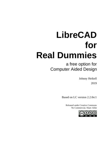
Chapter 1: CAD basicsCoordinate SystemsIn order to get the best out of LibreCAD it is wise to have a goodunderstanding of the coordinate system and how coordinates work.There are basically two types ofcoordinates: Cartesian and polar.The cartesian coordinate system isgenerally the standard system used inCAD programs. A specific point in adrawing is located by exact distancesfrom the x and y axes – for example, apoint in a drawing could be 60,45([x,y] note the comma that separatesthe two numbers).The polar coordinate system usesone distance and one angle to define apoint in a drawing. For example, apoint in a drawing could be 50 45,meaning 50 units long (r) and at anangle of 45 degrees (φ, note the signused for the angle).Cartesian (x,y) and Polar (r,φ) )coordinate systems [JH]With absolute coordinates, the coordinate points are entered in directrelation to the origin 0,0. To do this in LibreCAD you just enter the exactpoint in whichever units you are using, e.g. 60,45.In relative coordinates, the coordinate points are entered in relation tothe previous point entered (not the origin). For example, assume that yourfirst point is 20,45. You then enter the next point relative to this using the@ symbol. Thus @50,50 will put the second point 50 units horizontallyalong the X axis and 50 units vertically along the Y axis, giving thelocation 70,95.DimensionsSizes of objects within a drawing are conveyed with the use ofdimensions. Dimension distances may be shown with either of twostandardized forms, linear and ordinate dimensions.Linear dimensions – the usual case – use two parallel lines, calledextension lines and spaced at the required distance between two givenpoints. A line perpendicular to these extension lines is called a dimensionline, with arrows atits endpoints. Thenumerical indicationof the distance isplaced at themidpoint of thedimension line,adjacent to it or in agap provided for it.Object with linear dimensions in blue3
J. Heikell: LibreCAD for Real DummiesOrdinate dimensions use one horizontal and one vertical extension lineto establish an origin for the entire view. The origin is identified with 0,0placed at the ends of these extension lines.Distances along the x and y axes to other points on a drawing areindicated using additional extension lines with numerical informationplaced appropriately.ScalesDrawings are made to scale – it is not often a drawing has the same sizeas the object it represents (scale 1:1). Typically the drawing is smallerand engineering drawings have scales like 1:2, 1:5, etc. In architecture thescale 1:20 is common for small houses. A road map can have a scale of1:100.000, meaning 1 cm on the map equals to 1 km in nature. The otherextreme is nano-size objects that can have scales like 10.000:1 (alsoexpressed as 1:0.0001).dxf and .dwg file formatsDXF and DWG are the major file formats in CAD. Both are vectorgraphic file formats. Vector images maintain the same image quality atpractically any scale, making them ideal for design purposes. It is alsoeasy to edit the individual elements that form a vector image, as well as toadd and remove elements.DXF (acronym for Data eXchange Format) was developed as a tool toshare designs across different CAD and vector based programs. It stores2D vector images and can be used by almost all CAD software, as well asCNC (Computer Numerical Control) and GIS (Geographic InformationSystem) software. Every element of the drawing is spelled out in plaintext or ASCII format that contains the full range of alphanumericcharacters. Due to their file specifications, complex DXF drawingsbecome large – from several to hundreds of MB (megabyte). Whentransferring such a document, it has either to be split or compressed.DWG (for Drawing) is a proprietary format by AutoCAD-ownerAutodesk.Inc. It can handle both 2D and 3D information. The data isbinary, i.e., it is a series of 0’s and 1’s. A DWG document is typically 25%smaller that a DXF document.As usual in the IT business, the proprietary DWG format has beenreverse-engineered and is released as OpenDWG by the Open DesignAlliance https://www.opendesign.com/ – not without legal fights withAutodesk, Inc. OpenDWG is released under GPLv2, which Linus“Linux” Torvalds considers the only decent FOSS license (Free and OpenSource Software) – “I hate GPLv3.”The DWG format is still experimental in LibreCAD.Axonometric projectionAxonometric projection is a collective name for projection methods thataim to create the illusion of a 3D object on a two-dimensional surface.4
Chapter 1: CAD basicsAxonometric projection has been called technical projection because it isused in technical drawing, including CAD, and more lately in video andcomputer gaming. It is different from linear projection used by artists inthat it does not have vanishing points. Axonometric projection is closerto the parallel projection used in traditional Chinese paintings.There are three types ofaxonometric projection:isometric projection, dimetricprojection, and trimetricprojection. The image belowpresents a comparison of thethree. The differences may feelsubtle but there are basicdifferences, particularly in theway the three axes of spaceappear foreshortened.In isometric projection a unitalong an axis is equally long forall of the three axes (iso equal,uniform). That is, a centimeter isa centimeter along x, y, and zaxes (but observingtrigonometric equations); hencethe projection is named"isometric." Dimetric projection,“di” 2, uses different metricsfor axes.Isometric projection offersadvantages in engineering andarchitecture through the ease ofThe three types of axonometricdrawing due to fixed 120º (orprojection [Wikipedia, GNU Free30º, if you like) angles, as wellDocumentation License, Version 1.2]as when measures must be takendirectly from an image. However, isometric drawings are only visualguides, they should not be used as exact drawings. In addition they resultin perceived distortions because they are contrary to how human visionworks.A variant of isometric projection is “military projection,” which uses 90º(45º) angles.The isometric angle gives problems in computer games and for thatreason an angle of approximately 27º is used. To those interested in thesubject I can suggest the article at https://www.compuphase.com/axometr.htm , which discussesaxonometric projection from the computer gaming viewpoint.Multiview projectionA multiview projection is a type of orthographic projection that showsthe object as it looks from the front, right, left, top, bottom, or back (e.g.5
J. Heikell: LibreCAD for Real Dummiesthe primary views). There are two main standards in use, the first-anglestandard used primarily in Europe (ISO standard) and the third-anglestandard used in the US and Canada:Symbols used to define whether a projection is eitherfirst-angle (left) or third-angle (right). [WikipediaCommons]Linear projectionHuman vision is best adapted to processing 3D objects in 2D linearprojection. LibreCAD is not however intended for linear projection, but ithas a basic capability as will be demonstrated with a small test isChapter 4.6
2 Introduction to LibreCADFAQWhat is LibreCAD?LibreCAD is a free, open source 2D CAD software for Windows, Apple,Linux. It allows isometric 3D drawings to be made. True 3D systemsallow users to rotate and view a drawn object from any angle, even to“walk” into the object – a nice feature in architectural drawing.Most of the interface and handle concepts are analogous to AutoCAD,making it easier for users to switch to and from this type of commercialCAD applications. LibreCAD uses the AutoCAD’s .dxf file formatinternally to import and save files. It allows export to many other fileformats like png, jpeg, and pdf.LibreCAD is released under the GNU General Public License (GPLv2). Itcan be downloaded e.g. at http://librecad.org/ :LibreCAD home page at https://librecad.org/ Who are the competitors?AutoCAD, as hinted earlier, is the juggernaut in the drafting industry. Onecould say it is the Rolls Royce of CAD with a Rolls Royce price tag.DraftSight is perhaps the #2 in this field; a limited version is free forprivate use but for corporate users the price depends on the size of thecompany.A list of 2D and 3D CAD alternatives to LibreCAD can be found at: https://alternativeto.net/software/caduntu/ . However, I have not foundany direct competitor to LibreCAD. The main attributes I have been7
J. Heikell: LibreCAD for Real Dummieslooking for are: 2D, free and open source, no strings attached (not alimited version, no trial time, no registration needed, no piggy-backsoftware installed, etc.), fairly advanced solution, and the question of fileformats (particularly .dxf and formats suitable for printing – with PDFbeing important).The .dwg format (for drawing) is important to share drawings amongCAD programs. Presently this is only experimental in LibreCAD, but it isreportedly compliant with documents saved in AutoCAD 2007
drawing is located by exact distances from the x and y axes – for example, a point in a drawing could be 60,45 ([x,y] note the comma that separates the two numbers). The polar coordinate system uses one distance and one angle to define a point in a drawing. For example, a point in a drawing