Transcription
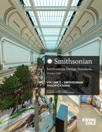
Smithsonian Design StandardsOctober 2021VOLUME 2 – SMITHSONIANSPECIFICATIONSSF PROJECT NUMBER: 1699622EWINGCOLE PROJECT NUMBER: 20160528
Smithsonian Design StandardsTable of ContentsVOLUME 1:Design Guidelines & Technical SectionsDesign Guidelines:Chapter 1-IntroductionChapter 2- About This DocumentChapter 3- General InformationChapter 4- Design RequirementsChapter 5- Quality RequirementsChapter 6- SustainabilityChapter 7- PlanningChapter 8- SiteChapter 9- Space RequirementsChapter 10- Building RequirementsChapter 11- Safety and Security Engineering RequirementsTechnical Sections:Division 01 – Supplementary Conditions for ConstructionDivision 02 – Existing ConditionsDivision 03 – ConcreteDivision 04 – MasonryDivision 05 – MetalsDivision 06 – Wood, Plastics, and CompositesDivision 07 – Thermal and Moisture ProtectionDivision 08 – OpeningsDivision 09 – FinishesDivision 10 – SpecialtiesDivision 11 – EquipmentDivision 12 – FurnishingsOctober 2021TOC-1
Smithsonian Design StandardsTable of ContentsDivision 13 – Special ConstructionDivision 14 – Conveying SystemsDivision 21 – Fire SuppressionDivision 22 – PlumbingDivision 23 – Heating, Ventilation and Air ConditioningDivision 26 – ElectricalDivision 27 – CommunicationsDivision 28 – Electronic Safety and SecurityDivision 31 – EarthworkDivision 32 – Exterior ImprovementsDivision 33 – UtilitiesVOLUME 2:Smithsonian Specifications:Section 01 32 50 – Building Information Modeling (BIM) RequirementsSection 01 56 39 – Site ProtectionSection 01 78 23 – Operation and Maintenance DataSection 01 91 13 – CommissioningSection 02 82 00 – Asbestos AbatementSection 02 83 00 – Work Activities Impacting Lead-Containing MaterialsSection 07 81 00 – Sprayed Fire-Resistant MaterialsSection 07 84 13 – Penetration FirestoppingSection 08 11 73 – Rolling Fire DoorsSection 10 44 00 – Fire Extinguishers, Cabinets, and AccessoriesSection 14 21 13 – Electric Traction Freight ElevatorsSection 14 21 23 – Electric Traction ElevatorSection 14 24 13 – Hydraulic Freight ElevatorSection 14 24 23 – Hydraulic Passenger ElevatorOctober 2021TOC-2
Smithsonian Design StandardsTable of ContentsSection 14 31 00 – EscalatorsSection 21 13 13 – Wet Pipe Sprinkler SystemsSection 21 13 16 – Dry Pipe and Preaction Sprinkler SystemSection 21 31 10 – Fire Pump SystemSection 27 05 00 – Common Work Results for CommunicationsSection 27 05 26 – Grounding and Bonding for Communications SystemsSection 27 11 00 – Communications Equipment Room FittingsSection 27 13 00 – Communications Backbone CablingSection 27 15 00 – Communications Horizontal CablingSection 28 31 11 – Addressable Fire Alarm SystemSection 32 91 00 – Planting Soil- TemplateSection 32 92 00 – Lawns and GrassesSection 33 16 15 – Water Storage Steel TanksVOLUME 3:Appendices:Appendix A – Security Design Criteria MatrixAppendix B – Required Security DrawingsAppendix C – Standard Security DrawingsAppendix D – Collection Storage Risk LevelsAppendix E – Smithsonian Declaration on the Collections Preservation EnvironmentAppendix F – Exhibit Fabrication Guide Appendix F1 – Exhibit Fabrication Guide Appendix F2 – Fire and Life Safety Checklist for Exhibit Construction Appendix F3 – General Notes for Exhibit Design Appendix F4 – Frequently Asked Questions about Exhibits Materials Appendix F5 – Approved/Prohibited Exhibit Materials [RESERVED]Appendix G – Fire Protection Commissioning Standards [RESERVED]October 2021TOC-3
Smithsonian Design StandardsTable of ContentsAppendix H – Summary of Enclosure Requirements for Common Use AreasAppendix I – Compact Storage Units (Mobile Shelving) Design SupplementAppendix J – Facilities Design Standards: Smithsonian Enterprises SupplementAppendix K – Smithsonian Enterprises Specialty Specifications Section 08 34 73 – Sound Control Door Assemblies Section 08 56 73 – Sound Control Windows Section 08 81 00 – Interior Glazing Section 10 22 13 – Wire Mesh Partitions Section 11 61 33 – Rigging, Curtain & Tracks Section 12 61 00 – Fixed Audience Seating – Planetarium Section 12 61 23 – Fixed Auditorium SeatsAppendix L – OCIO Appendices Appendix L1 – Cabling Specifications Appendix L2 – Wire Closet SpecificationsAppendix M – CPTED NarrativesAppendix N – Fire System Impairment PermitAppendix O – Laboratory Design StandardsOctober 2021TOC-4
Smithsonian Design StandardsSI Spec 013250: Building Information Modeling (BIM) RequirementsSECTION 01 32 50BUILDING INFORMATION MODELING (BIM) REQUIREMENTSPART 1 - GENERAL1.1A.SUMMARYSection includes requirements for Building Information Modeling including, but notlimited to, the following:1.2.3.4.5.6.B.Related Requirements:1.C.Development of BIM Execution PlanDevelopment of Construction Model(s)Development of Fabrication/Shop Drawings at Contractor’s option.Development of Coordination Model(s)Development of Coordination ReportAs-Built Model(s) and DrawingsDivision 01 section Operation and Maintenance Data for Facility Asset DataRequirements.Contractor’s Responsibility:1.2.3.Develop deliverables required in this Section.Contractor is solely responsible for the quality and accuracy of alldocumentation and submittals of this Section.The intent of BIM deliverables is to avoid interference and conflicts, optimizeconstruction sequencing, achieve greater efficiencies in cost estimating andproject coordination, and ensure access for maintenance, replacement orrepairs.a.b.D.Coordination: Contractor is solely responsible for the coordination offacility systems and equipment.Construction sequencing: Contractor is solely responsible to sequenceconstruction activities to facilitate the fabrication and installation ofsystems and equipment without interference, conflicts or delays inconstruction, and providing adequate access to effectively maintain andreplace systems and equipment.Existing Documents: The following building information, obtained and developed bythe Architect and/or Engineer during the design phase, may be available to theContractor:October 2021Volume 2- Specifications 01 32 50-1
Smithsonian Design StandardsSI Spec 013250: Building Information Modeling (BIM) Requirements1.2.3.4.5.6.7.E.Design Intent Model(s) (.rvt, .ifc, & .nws / .nwd)Contract Documents (.pdf)CAD Files (.dwg)Point Clouds (.rcs)Scans of the original building design drawings (.pdf)BIM PxP (.docx, .pdf)LOD Matrix(.xlsx, .pdf)SI BIM Practice Requirements:1.The following documents related to are available on the Smithsonian FacilitiesA/E Center website, under the Codes and Standards section and are applicableto BIM requirements:a.b.Smithsonian Facilities BIM Guidelines: Describes information,procedures, and responsibilities relevant to BIM work completed byarchitecture, engineering and construction (AEC) consultants in order toassure accurate and consistent deliverables.SF Revit Templates: BIM templates developed by Smithsonian Facilitiesare available for the Contractor to use when utilizing Autodesk Revit asthe model authoring software to populate with accurate project-specificfacility asset data.1) Scope of required facility data is described in the template and shouldbe modified to reflect actual Project requirements.1.2c.SF Revit Template Users Guide: This document, prepared by SmithsonianFacilities, describes how to incorporate and “SF Revit Templates” anddevelop the project BIM.d.SF BIM Project Execution Plan (PxP): Template document that definesthe expected BIM deliverables and guides the coordination of the projectteam, throughout the project lifecycle.DEFINITIONSA.As-Built Model: Building Information Model(s) developed by the Contractor thatrepresents the installed condition of facility elements.B.Building Information Model (BIM): A digital representation of physical andfunctional characteristics of a facility.C.BIM Project Execution Plan (PxP): A document prepared by the contractor, utilizing astandard SF PxP template that defines the expected BIM deliverables and guides theOctober 2021Volume 2- Specifications 01 32 50-2
Smithsonian Design StandardsSI Spec 013250: Building Information Modeling (BIM) Requirementscoordination of the project team, throughout the project lifecycle.D.Construction Model: Building Information Model(s) that demonstrates andcommunicates the facility data necessary to procure, fabricate, schedule or constructthe Project.E.Coordination: A process implemented to ensure the efficiency and harmony of therelationship of facility elements. Typically performed in a BIM environment byevaluating interferences, also called “clash detection”.F.Coordination Model: Building Information Model(s) that demonstrates andcommunicates the spatial relationship of facility elements.G.Coordination Report: A report developed to communicate and demonstrate thatthe facility elements have been properly coordinated and identify areas where issuesmay still exist.H.Design Intent Model: Building Information Model(s) that demonstrates andcommunicates the creative objectives of the designer.I.Fabrication/Shop Drawing: Drawing generated by the contractor from aConstruction Model based on the contract documents that communicates theinformation necessary to fabricate facility elements. Fabrication/Shop Drawingstypically contain one system and are intended for use of trade personnel to fabricate,assemble, and install facility elements.J.Facility Breakdown Structure: a system-oriented hierarchical decomposition of afacility into smaller components. Typically the facility breakdown structure is basedon disciplines, trades, described by Master Format.K.Facility Asset Data: Non-graphical information attached to an object in a BuildingInformation Model that defines various characteristics of an object.L.Furnishings: Built-in or movable cabinets, casework, seating or other appurtenancesprovided by the Contractor.M.Interference: Spatial conflict between facility elements.N.Level of Development: Describes the minimum dimensional, spatial, quantitative,qualitative, and other data includes in a model element as defined in the SF BIMGuidelines.October 2021Volume 2- Specifications 01 32 50-3
Smithsonian Design StandardsSI Spec 013250: Building Information Modeling (BIM) RequirementsO.Level of Accuracy: Describes the minimum dimensional accuracy of element(s) asdefined in the SF BIM Guidelines.P.Conformed Model – Updates the Design Intent Model for those aspects maintainedby the designer to record authorized design changes during construction.1.3SUBMITTALSA.BIM Project Execution Plan (PxP): Prepare and submit a plan utilizing the “SF BIMExecution Plan” framework document available on the Smithsonian FacilitiesArchitectural-Engineer Information Center website. Submit t h e PxP in PortableDocument Format (PDF) within 60 days after contract award. BIM Project ExecutionPlan (PxP) shall be updated as required and submitted with Final As-Built Model(s).B.Submit plans, sections and other review documents monthly, in .pdf format. Toinclude field changes that affect the accuracy of the Construction and As-Built Models.C.Construction Model(s): Prepare and submit, on a quarterly basis, ConstructionModel(s) that contain spaces, objects and data required to purchase, fabricate,and install project elements. Graphically indicate construction progress inConstruction Model(s). Construction Model(s) are to be submitted with allCoordination Model(s) link into one central model using Autodesk Navisworks with alldisciplines.D.Coordination Model(s): Prepare and submit Coordination Model(s) on a monthlybasis. Coordination Model(s) are to be based on the facility breakdown structure ofthe Design Intent Model. Contractors are to perform all work utilizing 3D modelingsoftware in order to facilitate seamless coordination with BIM workflows and fileintegration. All design elements should be produced three-dimensionally in programsthat can output file formats supported by Autodesk Navisworks. CoordinationModel(s) are to be submitted using Autodesk Navisworks with all disciplines.1.2.E.Coordination Model(s) are to be submitted prior to fabrication, andinstallation of any element within the area represented within theCoordination Model(s).Fabrication/Shop Drawings and Construction Model(s) are to be integratedinto the Coordination Model(s) or otherwise referenced in the CoordinationModel(s).CAD Drawings. Export CAD documents from the BIM authoring application in aformat conforming to SI requirements. Reference the “SF Revit Template UsersGuide” and “SF CAD Guidelines”.October 2021Volume 2- Specifications 01 32 50-4
Smithsonian Design StandardsSI Spec 013250: Building Information Modeling (BIM) RequirementsF.Coordination Report: Prepare and submit a written Coordination Report generatedfrom the Coordination Model(s) prior to fabrication, and installation of any facilityelement within the area represented within the Coordination Model(s).1.Coordination Report is to be submitted in Portable Document Format (PDF).G.Final As-Built Model(s): After installation of all Facility Elements, update and submitAs-Built Model(s) to document the condition of the facility upon completion ofconstruction. As-Built Models are to be submitted with all Model(s) and link into onecentral model using Autodesk Navisworks with all disciplines.H.As-Built Fabrication/Shop Drawings: After installation of all Facility Elements,update and submit Fabrication/Shop Drawings to document the condition of thefacility upon completion of construction.I.By submitting the As-Built Model(s) and Coordination Report(s), the Contractorconfirms that the following have been accomplished:1.2.3.4.5.J.Existing conditions have been adequately identified, documented, and verified.Facility elements are properly represented within the Model(s).Access to maintain, repair, or replace facility elements has been identified andvalidated.Clearances, such as those required by code and equipment specifications, havebeen identified and validated.Interferences have been identified and resolved.Data Capture (Laser Scan): Survey, prepare and submit Point Cloud files at key stagesduring the construction process including but not limited to, open trenches, rough-in /close-in, project completion, etc. as directed by COTR. This survey to be utilized toensure all As-Built conditions for the project are documented properly. This willinclude establishing the necessary Survey Control Network throughout the site andscanning as many points as may be required to create a reliable point cloud of allinterior and exterior surfaces of the building. The required object surface density ofscanning shall be a minimum of 6mm (¼”). RGB color shall be mapped to both theexterior and interior scans. Point Cloud data should be broken into separate data setsas directed by COTR and be registered in the same coordinate frame (origin point) asthe As-Built Model(s). Point cloud data to be submitted using Autodesk Recap.PART 2 - EXECUTION2.1CONTRACT DOCUMENTS AND DESIGN INTENT MODEL(S)October 2021Volume 2- Specifications 01 32 50-5
Smithsonian Design StandardsSI Spec 013250: Building Information Modeling (BIM) RequirementsA.The Contract Documents and Design Intent Model(s) will be provided to theContractor for reference in the development of the Construction and CoordinationModel(s) and Fabrication/Shop drawings. The Contract Documents and DesignIntent Model(s) communicate creative objectives of the Architect and/or Engineer,and are not intended to be used for fabrication and construction of the facility inthat the size, arrangement, and level of development of facility elements may nothave the necessary tolerances to allow for fabrication.B.The Contract Documents are the binding document(s) of record, the Design IntentModel(s) are provided for reference only.2.2A.2.3A.2.4DEVELOPMENT OF BUILDING INFORMATION MODELING PLAN (BIM PxP)The BIM PxP shall be approved by SI prior to development of Construction /Coordination Model(s), and development of Facility Asset Data. Informationcontained in the BIM PxP shall conform to the “SF BIM Guidelines”.INSPECTION OF EXISTING CONDITIONSPrior to the development of the Construction / Coordination Model(s), inspect andverify accuracy of information communicated in the Contract Documents and DesignIntent Model with respect to the existing conditions. Notify Architect if any conflictsamong Contract Documents, the Design Intent Model, and existing conditions arediscovered. Do not proceed with development of Construction / CoordinationModel(s) until conflicts are resolved to the satisfaction of SI.FACILITY ASSET DATAA.See Spec 01 section OPERATION AND MAINTENACE DATA for asset data requirementsB.The Contractor is responsible for incorporating Design Intent Model and Facility AssetData Spreadsheet revisions into the Construction and As-Built Model(s) in order tomaintain an up-to-date basis for Building Information Modeling throughoutconstruction.C.Contractor is responsible for incorporating the following Asset Data from SF FacilityAsset Data Spreadsheet into the Construction and As-Built Model(s):1.2.3.October 2021Asset ID# (SI will provide)Asset Name (SI will provide)SpecID (CSI Master Format 2016)Volume 2- Specifications 01 32 50-6
Smithsonian Design StandardsSI Spec 013250: Building Information Modeling (BIM) ENT OF CONSTRUCTION MODEL(S)A.The intent of the Construction Model(s) is to communicate the necessary informationto construct the facility including size, location, and arrangement of both existing toremain and new elements and to incorporate the as-built conditions.B.Develop Construction Model(s) based upon Contract Documents, Design IntentModel(s), and verified existing conditions.C.Construction Model(s) shall accurately reflect the geometry and details of existingand new elements within the facility.1.2.Use manufacturer or custom model elements to accurately reflect thecomponents detailed in documents submitted for approval.Update the model elements to accurately reflect any revisions to geometry ordetails arising from the submittal review process.D.Construction Model(s) are to have a consistent origin that can be referenced to a realworld datum or benchmark, located as required in the “SF Revit Template Users’Guide”.E.Quality Control. The Construction Model(s) will undergo automated model checksutilizing rulesets, as described in the “SF BIM Guidelines” document and visual reviewby SI.F.The Construction Model(s) are to reflect all necessary access and clearances.G.The Construction Model(s) will include, but not be limited to, the following elementswith all necessary intelligence included to produce plans, sections, elevations, riserdiagrams, and schedules as applicable:1.2.Substructure: All foundations, subgrade enclosures, slabs-on-grade, and waterand gas utility connections. Substructure elements shall be depicted with allnecessary recesses, curbs, pads, slopes, closure pours, expansion/constructionjoints, and major penetrations depicted.Shell: All superstructure, exterior vertical enclosures, and exterior horizontalenclosures, including a depiction of expansion/construction joints.a.October 2021Superstructure: All columns, primary and secondary framing members,Volume 2- Specifications 01 32 50-7
Smithsonian Design StandardsSI Spec 013250: Building Information Modeling (BIM) Requirementsb.and bracing for the roof and floor systems (including decks).Exterior Vertical Enclosures: Exterior vertical enclosures shall be depictedto the exact height, length, width and ratings (thermal, acoustic, fire) toproperly reflect element types. Exterior windows, doors and grillesincluding hardware sets, louvers and vents, and wall appurtenances shallbe depicted to represent their actual size, type and location.3.Interiors: All interior partitions, windows, doors and grilles, louvers and vents,raised floors, and ceilings, depicted to represent their exact location, height,length, width and ratings (thermal, acoustic, fire) to properly reflect elementtypes.4.Services: All elevators, escalators, plumbing, HVAC, fire protection, electrical,communications, electronic safety and security, and integrated automationelements, including all major openings and penetrations, cable trays, cablebundles and pipe grouping. All clearances and insulation shall be accountedfor in the model for use in interference management and maintenance accessrequirements. Nonpermanent items are not required to be modeled or containfacility data.a.b.c.d.e.f.g.h.5.October 2021Plumbing: All plumbing elements including plumbing piping and fixturelayouts, floor and area drains, and related equipment.Heating, Ventilation, And Air Conditioning (HVAC): All heating, ventilation,and air conditioning (HVAC) elements including piping, valves, ductworkfixture lay- outs and related equipment.Fire Protection: All fire protection elements including piping, valves,and related equipment.Electrical: All electrical elements including conduit, fixture layouts andrelated equipment (including power for systems furniture).Communications: All communications and low voltage systemselements including conduit and related equipment.Security: All Electronic Safety and Security elements including conduitand related equipment.Integrated Automation: All integrated automation elements includingconduit and related equipment.Model all elements larger than 38mm (1-1/2 inch) in diameter for anytrade. When equal or smaller element are grouped or run in a uniformpath. That group of elements shall be modeled when larger than 152mm(6 inches).Equipment and Furnishings: All fixed equipment and furnishings, depicted torepresent their exact location, height, length, width, configuration, materials,Volume 2- Specifications 01 32 50-8
Smithsonian Design StandardsSI Spec 013250: Building Information Modeling (BIM) Requirements6.7.H.2.6finishes, and mechanical and electrical requirements.Special Construction and Demolition: All special construction and demolitionincluding special construction, facility remediation and demolitionSitework: All sitework elements, including site improvements, liquid and gasutilities, electrical site improvements, and site communications.Construction Model(s) must be revised and certified by the Contractor prior toinstallation of facility elements contained within the models.DEVELOPMENT OF COORDINATION MODEL(S)A.Develop Coordination Model(s) that combine facility elements contained within theConstruction Models with other facility elements depicted in the Design Intent Modelin order to review the efficiency and harmony of the relationship of the facilityelements.B.Verify that all facility elements are properly represented within the Constructionand Coordination Model(s) prior to coordination.C.Conduct the following interferences checks to ensure that there are no conflicts inthe installation of facility elements.1.2.3.4.5.Substructure/Shell vs InteriorsSubstructure/Shell vs Equipment and Furnishings provided by ContractorInteriors vs Equipment and Furnishings provided by Contractor.Substructure vs. ShellServices vs other ctober 2021Services vs Substructure/ShellServices vs InteriorsServices vs Equipment and FurnishingServices vs Site workPlumbing vs HVACPlumbing vs Fire ProtectionPlumbing vs ElectricalPlumbing vs CommunicationsPlumbing vs Electronic Safety and SecurityHVAC vs Fire ProtectionHVAC vs ElectricalHVAC vs CommunicationsHVAC vs Electronic Safety and SecurityFire Protection vs ElectricalVolume 2- Specifications 01 32 50-9
Smithsonian Design StandardsSI Spec 013250: Building Information Modeling (BIM) Requirementsk.l.m.n.o.7.Fire Protection vs CommunicationsFire Protection vs Electronic Safety and SecurityElectrical vs CommunicationsElectrical vs Electronic Safety and SecurityCommunications vs Electronic Safety and SecurityADA AccessibilityD.Coordination Model(s) shall be free of interferences prior to installation of anyassociated facility element.E.Update the Coordination Model(s) to reflect changes throughout construction priorto installation of any associated facility element.2.7A.COORDINATION REPORT(S)Develop Coordination Reports identifying outstanding issues after the developmentof the Coordination Model(s), including but not limited to:1.Clashes:a.b.c.d.2.3.4.5.Itemize number of clashes.Clash CategoryDescribe clashes.Describe the resolution of clashes and other conflicts.Design changes.Differing site conditions.Hazardous or safety related issues.Assets installed and assets pending installation.B.The report shall be organized by CSI Master Format 2016 specification section or bytradeC.The issues identified within the Coordination Report are to be addressed by theContractor in consultation with the SI and the Architect / Engineer prior to installationof facility elements.D.The Contractor is solely responsible for the cost of remedying any clashes that couldhave been discovered during the clash detection process.2.8A.INSTALLATIONInstall facility elements in accordance with approved Construction Model(s),October 2021Volume 2- Specifications 01 32 50-10
Smithsonian Design StandardsSI Spec 013250: Building Information Modeling (BIM) RequirementsFabrication/Shop Drawings, Coordination Model(s), and Coordination Reports. Anyvariance from these documents shall require approval by the SI C O T R prior tothe installation of the associated facility elements.B.Adjust Coordination Model(s) throughout construction to reflect all changes made tothe approved Contract Drawings and Specs, Design Intent Model, andFabrication/Shop Drawings.C.Maintain an up-to-date Fabrication/Shop Drawing set and Coordination Model(s)for all parties to access.2.9A.AS-BUILT MODEL AND DRAWINGSUpon completion of the installation of facility elements, update and deliver As-BuiltModel(s) and Fabrication/Shop Drawings to document the condition of the facilityupon completion of construction.1.2.3.The updated Construction and Coordination Model(s) are considered the AsBuilt Model for this facility. These models shall clearly indicated portions of thefacility that are constructed and portions where construction is pending.Model(s), CAD and SI-GIS exports are to be delivered in native file formats aswell as file formats and naming conventions consistent with SF standards.Reference the “SF Revit Templates Users Guide” and “Smithsonian FacilitiesBIM Guidelines” guidance documents.All models shall be linked and submitted using Autodesk Navisworks.END OF SECTION 01 32 50October 2021Volume 2- Specifications 01 32 50-11
Smithsonian Design StandardsSI Spec 015639: Site ProtectionSECTION 01 56 39SITE PROTECTIONSECTION 01 56 39 – SITE PROTECTION1.1. Tree Protection: The following procedures shall be followed for any project taking placeon Smithsonian Institution grounds when any tree may be impacted.26.1.1 Prior to any work taking place or vehicles and equipment being brought on site, theContractor shall meet with the Smithsonian Gardens (SG) Arborist, LandscapeArchitect, and other appropriate staff to discuss and plan for tree protectionmeasures.26.1.2 The project site shall be defined, and all trees that may be impacted identified.26.1.3 For every tree that may be impacted, the Critical Root Zone (CRZ) shall be identified.The CRZ shall be determined by the following method:A. Measure the diameter of the tree at breast height (4.5 feet above grade), and forevery inch of diameter, measure a distance of 1.5 feet from the trunk. The areainside this circle is the CRZ.26.1.4 The following activities shall NOT take place in the CRZ, unless specified in a writtentree protection plan pre-approved by SG:A. Stockpiling of materials, soil, mulch, or debris.B. Parking or driving of equipment or vehicles.C. Compaction of soil from any activity, including the placement of vehicles,materials, equipment, or outriggers.D. Trenching, tunneling, grade changing, or removing soil.E. Cutting, tearing, or grubbing of tree roots.F. Wounding trees in any way.G. Changing the site drainage.H. Dumping or spraying gasoline, oil, dirty water, or any chemical or material thatcan damage a tree.I. Using trees as backstops, winch supports, or anchors.J. Attaching anything to trees, including, but not limited to, signage, nails, screws,spikes, ropes, and wires.October 2021Volume 2- Specifications 01 56 39-1
Smithsonian Design StandardsSI Spec 015639: Site Protection26.1.5 Once the CRZ’s have been identified, fencing shall be erected on the edge of the CRZto prevent any activities from taking place in those zones. Fencing can consist ofminimum 48” height temporary chain link fence, welded wire fence with steel tposts, or any other type of fence approved by SG through the COTR. Warning signsshall be placed on each CRZ fence, be a minimum size of 8.5 x 11 inches, and statethe following: “TREE PROTECTION ZONE. This fence shall not be removed.”Removal of fences, even temporarily, to allow deliveries or equipment access is notallowed without the prior approval of the Smithsonian Gardens Arborist or otherqualified SG staff.26.1.6 In the event that it is impossible to complete a project without some activity in aCRZ, a written tree protection plan pre-approved by SG shall be implemented.Tree protection plan requirements may include impact avoidance, rootprotection groundcover, air excavation and root pruning, supplementalwatering, chemical applications, branch pruning and/or tiebacks, and/or anynumber of other industry standard tree protection methods generally reviewedin the Managing Trees During Construction Best Management Practices manual(Fite and Smiley 2016) and other literature reviewing tree care industry standardtree protection practices.26.1.7 During the project, project activities shall not physically impact the tree ordelineated CRZ, unless described in tree protection plan pre-approved by SG. Theimpacted trees shall also be closely monitored for signs of shock or stress. Anydecline in tree condition that is no
5. Scans of the original building design drawings (.pdf) 6. BIM PxP (.docx, .pdf) 7. LOD Matrix(.xlsx, .pdf) E. SI BIM Practice Requirements: 1. The following documents related to are available on the Smithsonian Facilities A/E Center website, under the Codes and Sta