Transcription
Michigan Department of TransportationField Manual forConcrete AnchoringPrepared by1st Edition February 2015
Engineering Manual PreambleThis manual provides guidance to administrative, engineering, and technical staff. Engineeringpractice requires that professionals use a combination of technical skills and judgment indecision making. Engineering judgment is necessary to allow decisions to account for uniquesite-specific conditions and considerations to provide high quality products, within budget, andto protect the public health, safety, and welfare. This manual provides the general operationalguidelines; however, it is understood that adaptation, adjustments, and deviations are sometimesnecessary. Innovation is a key foundational element to advance the state of engineering practiceand develop more effective and efficient engineering solutions and materials. As such, it isessential that our engineering manuals provide a vehicle to promote, pilot, or implementtechnologies or practices that provide efficiencies and quality products, while maintaining thesafety, health, and welfare of the public. It is expected when making significant or impactfuldeviations from the technical information from these guidance materials, that reasonableconsultations with experts, technical committees, and/or policy setting bodies occur prior toactions within the timeframes allowed. It is also expected that these consultations will eliminateany potential conflicts of interest, perceived or otherwise. MDOT Leadership is committed to aculture of innovation to optimize engineering solutions.The National Society of Professional Engineers Code of Ethics for Engineering is founded on sixfundamental canons. Those canons are provided below.Engineers, in the fulfillment of their professional duties, shall:1.2.3.4.5.6.Hold paramount the safety, health, and welfare of the public.Perform Services only in areas of their competence.Issue public statement only in an objective and truthful manner.Act for each employer or client as faithful agents or trustees.Avoid deceptive acts.Conduct themselves honorably, reasonably, ethically and lawfully so as to enhance thehonor, reputation, and usefulness of the profession.
Table of ContentsIntroduction and Purpose. 3Part I: General . 4Types of Anchors. 4Pros and Cons. 8Plans and Specifications. 9Design Methodology and Failure Modes.11Part II: Structural Adhesive Anchoring Systems.16Types .16Installation.17Acceptance Testing.20Proof Testing.20Field Testing.20Equipment and Methods.21Important Testing Notes.27Inspection Checklist.28Part III: Structural Mechanical Anchoring Systems .29Types .29Installation.30Acceptance Testing.31Proof Testing.31Field Testing.31Equipment and Methods.32Important Testing Notes.35Inspection Checklist.36Part IV: Lane Ties and Concrete Pavement Anchoring.37Appendix A: Required Loads for Proof Tests andField Tests of Structural Anchoring Systems.38Appendix B: MDOT Form 1928(Adhesive Anchoring System Proof Test).39Appendix C: MDOT Form 1927(Mechanical Anchoring System Proof Test).402Field Manual for Concrete Anchoring
Introduction and PurposeThe purpose of this field manual is to provide an overview of the structuralanchoring systems the Michigan Department of Transportation (MDOT)uses for attaching to hardened concrete. These systems provide the abilityto post-install attachments or anchor reinforcing bar to existing structuresin order to perform the following types of work:n Widening bridges;n Replacing bridge barrier on an existing deck;n Attaching bridge mounted signs;n Installing bridge bearing anchor bolts; andn Lane ties and concrete pavement anchoring.It is important to think of everything that goes into installing a structuralanchor as part of a system. These systems are used to resist substantialstructural loads and their performance is extremely dependent on properinstallation. For the system to work as designed, the correct productmust be used with the correct tools, installation procedures, and testingprocedures; specifically per the manufacturer’s instructions as amendedby MDOT specifications. In general, a cast in place anchor is superior to apost-installed anchor; however, in many cases a properly installed structural anchoring system can be used to replace an anchor that has been castin concrete incorrectly or was omitted.This manual is divided into the following four parts:n General;n Structural adhesive anchoring systems;n Structural mechanical anchoring systems; andn Lane ties and concrete pavement anchoring (non-structural).Contact MDOT Bridge Field Services for questions or support related tostructural anchoring systems.Field Manual for Concrete Anchoring3
Part I: GeneralTYPES OF ANCHORSStructural anchoring systems can be divided into two types, adhesiveand mechanical, and within each type there are several subtypes.Adhesive anchors can include different chemical elements, compounds,fine aggregate or other inert fillers, and may be packaged in bulk orsingle application sizes, while mechanical anchors include expansionanchors and undercut anchors.All adhesive anchoring systems transfer load from the anchor into theconcrete through bond strength of the adhesive, while most mechanicalanchors transfer load through friction between the concrete and theexpanded portion of the anchor. Undercut anchors transfer load throughbearing of the bottom of the anchor onto concrete, although thedepartment does not currently have any undercut anchors approved foruse in the MDOT Materials Source Guide (MSG). Undercut anchors orother anchor types not listed on the QPL may be covered by a projectspecial provision.While many anchoring systems have similarities in their installationprocedures, most have product specific instructions or product specifictools. For example, some anchoring systems require a special drill bit,while some mechanical anchoring systems require a unique tool toproperly set the anchor. Examples of these different types of anchoringsystems can be seen in Figures 1-7 on the following pages. Parts II andIII of this manual cover the different systems and their installationprocedures in more detail.4Field Manual for Concrete Anchoring
Figure 1. Adhesive anchoring system, two component epoxy type.Figure 2. Instructions and nozzle (with extension) packaged with epoxy.Field Manual for Concrete Anchoring5
Figure 3. Adhesive anchoring system, capsule type.Figure 4. Mechanical anchoring systems, expansion wedge type.6Field Manual for Concrete Anchoring
Figure 5. Mechanical anchoring system, expansion drop-in type.Figure 6. Mechanical anchoring system, self-drilling expansion type.Field Manual for Concrete Anchoring7
Figure 7. Mechanical anchoring system, undercut type.PROS AND CONSAdhesive and mechanical anchoring systems have their advantages anddisadvantages as shown in the table below.Table 1. Advantages and disadvantages of anchoring systems.AdhesiveMechanical8ProsConsHigher strength/displacement ratioCannot be loaded untiladhesive curesCan be used withreinforcing barSensitive to temperatureand limited shelf lifeCan be loadedimmediatelySensitive to holedimensions and vibrationsUnlimited shelf life andno temperature concernsRequires special toolsField Manual for Concrete Anchoring
In most cases the department’s preference is for adhesive anchoringsystems over mechanical anchoring systems which is reflected in most ofMDOT’s details, guides, manuals, and standards. Mechanical anchoringsystems have been found to be more sensitive to installation proceduresand do not perform as well in-service as adhesive anchoring systems.PLANS AND SPECIFICATIONSThe type of anchoring system (adhesive vs. mechanical), diameter of theanchor, the embedment depth, and the hole diameter should all be shownon the design plans (hole diameter may change slightly depending onthe particular product chosen). Only anchoring systems on the MDOTQualified Products List (QPL) may be used, unless otherwise specifiedor approved by the Engineer. Sections 712.03J and 712.03K of the QPLlist the currently approved adhesive and mechanical anchoring systems,respectively. If a product is not listed on the QPL but the contractor orsupplier is claiming it was approved, it may be listed as a pending QPLupdate on the MDOT web page for the Materials Source Guide. In thiscase, the manufacturer will have a recently issued approval letter from thedepartment.The basic requirements for installing adhesive and mechanical anchoringsystems are listed in 712.03J and 712.03K, respectively, of the MDOT 2012Standard Specifications for Construction (SSC). While each anchoringsystem may have unique aspects for installation and the manufacturer’sprocedures should be followed, MDOT specifications govern where thereis conflict. The following are examples of how a manufacturer’s specifications may conflict with MDOT specifications:n A manufacturer may state that their product can be installed at35 degrees Fahrenheit (F) or lower, but MDOT requires atemperature of 50 degrees F and rising, which applies not onlyto ambient temperature but to the concrete temperature as well(section 712.03J of the SSC).Field Manual for Concrete Anchoring9
n A manufacturer may state that their product can be installedin damp or wet holes, but MDOT requires the hole to be dry(712.03J.1 of the SSC).n A manufacturer may state that an embedment depth of six timesthe anchor rod/bar diameter can be used, but MDOT requires aminimum embedment depth of nine times the diameter of threadedrod, or twelve times the diameter for reinforcing bar (section7.06.02B of the MDOT Bridge Design Manual).The following list includes some of the common manufacturer equipment and procedures that can vary from one manufacturer to another orone product to another. Because of the variation it is important that themanufacturer’s recommendations be reviewed by the contractor and theinspector prior to installation.Adhesive Anchoring SystemsDrill Bit. Some manufacturers require the use of a special drill bit,while some may allow a core bit.Hole Diameter. Typical required hole diameter is 1/16 - 3/16 inch greaterthan the anchor bolt or nominal reinforcing bar diameter. The wrong sizehole can significantly reduce capacity.Cleaning. Some manufacturers may require specific tools and steps toclean the holes, while some may require compressed air.Nozzles. Each product has its own mixing nozzle that was designedspecifically to mix the components of that particular product;only use nozzles that come with the product.Cure Time. All adhesives have specific cure times that are temperaturedependent.10Field Manual for Concrete Anchoring
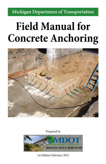
Mechanical Anchoring SystemsDrill Bit. See above.Hole Diameter. See above.Cleaning. See above.Torque Wrench. Some manufacturers require a torque wrench to properlyset the expansion element at the base of the anchor. Torque wrenchesshould be calibrated to ensure they are functioning properly.Setting Tools. Some manufacturers require the use of special tools to setthe anchor before loading it.DESIGN METHODOLOGY AND FAILURE MODESThe design of anchoring systems depends on variables including embedment depth, anchor spacing, edge distance, concrete strength, anchorsteel type, and direction of loading. The basic premise is to ensure that theconnection to the concrete, whether through bond, friction, or bearing,does not fail before the anchor steel begins to yield; this provides for aductile failure with some warning.There are three basic failure modes for both adhesive and mechanicalanchoring systems (see below in Figure 8):n Failure of the anchor steel;n Concrete (breakout) failure; andn Anchor connection failure (adhesive bond or mechanical friction).Field Manual for Concrete Anchoring11
NNNSTEEL FAILURECONCRETE BREAKOUTBOND FAILUREFigure 8. Adhesive anchoring system failure modes.The typical concrete failure of an anchor in tension is a conical shape thatbegins at the base of the anchor and terminates at the concrete surfacesome distance away from the anchor. A concrete failure can also occur incombination with an anchor connection failure. For example, the bond/friction force is exceeded by the applied load and the anchor displacessome amount until the concrete fails. In this case the concrete failure conebegins at some point between the base of the anchor and concrete surface.Figure 9 illustrates an example of bond failure; note the failure of thebond to both the steel and concrete. This is the result of a low temperatureinstallation where the epoxy never fully cured, despite being within themanufacturer’s permitted temperature range. Figure 10 illustrates anexample of concrete failure; note no bond failure on either the steel orconcrete.12Field Manual for Concrete Anchoring
Figure 9. Anchor depicting adhesive bond failure.Figure 10. Anchor depicting concrete conical failure(excess concrete removed).Field Manual for Concrete Anchoring13
The capacity of an adhesive anchor is reduced when an edge(break in the surface) or other loaded anchors are near the theoreticalconcrete failure cone of the anchor. This is incorporated into the designof the system through reduction factors for edge distance and anchorspacing, which vary depending on the anchor system. Figure 11 illustratesthe approximate concrete conical failure of one anchor of a two anchorsystem superimposed on the photograph. Superimposing the approximateconcrete conical failure of the second anchor on the first, as shown inFigure 12, shows the overlapping cones that lead to a reduction in capacitycompared to the strength of two separate and independent anchors.Note that in both cases the edge distance encroaches on the failure conesand acts to further reduce the capacity. Edge distance can be a verticaldrop or a gradual elevation change. They both have a negative effect onthe pullout capacity of the anchor.Figure 11. Approximate failure cone of the anchor on the right.14Field Manual for Concrete Anchoring
Figure 12. Approximate overlapping failure cones, resulting in reducedcapacity of each anchor.The department’s minimum embedment depths for adhesive anchorsystems were developed based on extensive testing of the products on theQPL. Although many manufacturers provide allowances for shallowerembedment depths, MDOT retains its minimum embedment depthrequirements to ensure any product from the QPL be able to develop125 percent of the yield strength of an ASTM A307 threaded bar and anASTM A615 or A996 Grade 60 bar reinforcement, at embedment depthsof nine times the diameter and 12 times the diameter, respectively.Table 2. Minimum Adhesive Anchor System Embedment RequirementsAnchor TypeMinimum EmbedmentASTM A307 threaded bar (36 ksi)9 x bar diameterASTM A615 or A996bar reinforcement (60 ksi)12 x bar diameterField Manual for Concrete Anchoring15
For mechanical anchoring systems, some manufacturers list multiplepermitted embedment depths. For these cases, the minimum embedmentdepth MDOT allows is listed on the QPL, when applicable.Part II:Structural Adhesive Anchoring SystemsAdhesive anchor is a general term implying the use of one of the variousadhesives used to bond anchors to hardened concrete. Subsection 712.03Jof the current edition of the QPL for structural adhesive anchoringsystems includes epoxy adhesives, methacrylates, urethane-methacrylates,and cementitious grout. With all of these systems the hole diameter,depth, cleanliness, and proper adhesive mixing are critical to achievingthe design strength of the system. The manufacturer’s recommendationsshould be followed unless they conflict with MDOT specifications inwhich case MDOT specifications govern.NOTE: MDOT has a moratorium on adhesive anchors placed in sustainedtensile applications due to the possibility of creep failure; overheadinstallation is not permitted. Multiple ceiling panel failures using overheadadhesive anchors occurred after the I-93 ‘Big Dig’ project in Boston, MA.Creep of the adhesive was found to be a major contributing factor.TYPESTwo-Part Epoxy Adhesives. The most common type of adhesive anchoring system is shown in Figure 1, although the component ratios can varybetween products. They can achieve final cure in anywhere from one hourto 48 hours depending on temperature and the specific components used.The viscosity of epoxy adhesives can vary widely.Methacrylate Adhesives. Similar to epoxy adhesives in that they aretwo-part systems that must be thoroughly mixed. These types typicallyhave shorter curing times than most epoxies.16Field Manual for Concrete Anchoring
Capsules. As shown in Figure 3, capsules eliminate the need for a dispensing system or mixing nozzles, but do require special threaded rods with abeveled end to rupture and mix the capsule in the hole. Capsules require aspecial drill attachment as well.Cementitious Grouts. Although there is only one cementitious grout currently on the QPL it is used frequently on department projects. The necessary hole diameter is larger than that of epoxy or methacrylate adhesives,and due to low viscosity, cannot be used in horizontal applications.INSTALLATIONInstallation is critical to the performance of adhesive anchor systems.The majority of failures are due to installation errors and more specificallycleaning of the drilled hole, which if not done properly can reducecapacity by 50 percent or more. Using a combination of brushing andforced air (see Figure 13) is recommended by most if not all manufacturersand is a best practice regardless of manufacturer’s recommendations.Figure 13. Brushes and air used for cleaning holes.Field Manual for Concrete Anchoring17
Precautions should be taken to ensure drilled holes are perpendicular tothe surface of the concrete. Edge spalls or other damage at the surface ofthe drilled holes should be completely filled in with adhesive. If duringdrilling, existing reinforcement is encountered, contact the Engineer todetermine how far a new hole can be drilled from the original hole andhow that will impact the attachment. Per section 712.03J.1 of the SSC, thecontractor is to “Propose a method that does not cut or damage existingreinforcing steel”. In most cases a pachometer (Figure 14), steel covermeter or Ground Penetrating Radar (GPR), as seen in Figure 15, can beused to locate existing reinforcement prior to drilling.Figure 14. Pachometer used for locating bar reinforcement.18Field Manual for Concrete Anchoring
Figure 15. GPR used for locating bar reinforcement.Proper mixing of the adhesive is critical. The nozzles that are providedwith the adhesive must be used and the components must be thoroughlymixed before they are injected in the hole. Therefore, when a new supply (cartridge) of adhesive is used the portion at the beginning must bediscarded and not placed in the hole until the product exiting the nozzleis completely homogeneous and the individual components cannot be detected. After thoroughly mixing the adhesive, the tip of the nozzle shouldbe placed at the bottom of the hole and slowly drawn out as the adhesive isinjected. Extensions can be placed on the nozzles (see Figure 2) for narrowand/or deep holes.After filling the hole with adhesive, the anchor should be placed with atwisting motion as it is pushed downward to help distribute the adhesivearound the bar and eliminate trapped air. If adhesive is not observed tooverflow the hole after the anchor has been placed, it must be removedand re-installed. The gel time or working time, and the final cure timemust be observed, based on the current temperature.Field Manual for Concrete Anchoring19
ACCEPTANCE TESTINGAll adhesives go through a rigorous review and testing process in orderto be placed on the QPL. Regardless of QPL status, all anchoring systemsmust undergo additional testing in the field on a per project basis in theform of proof testing and field testing, to address different aspects ofperformance and consistency.Proof Testing (section 712.03J.1 of the SSC). Three anchors, representativeof anchors to be installed on the project, are installed by the contractor ona separate concrete block and tested by the Engineer. Anchors for prooftesting should be placed such that edge distance or spacing does not reducecapacity. They must develop 125 percent of the yield strength of the barwith less than 1/16 inch of slip. Once a product is placed on the QPL it isnot retested for QPL acceptance unless performance concerns have beennoted. Over time the formulation of products on the QPL and variouschemicals and their suppliers may change. Therefore the proof testing ensures that the product is still capable of developing the same capacity as itdid when it was added to the QPL. Proof testing also verifies the contractorcan correctly install anchors before doing so on the permanent structure.Field Testing (section 712.03J.2 of the SSC). During the first day ofproduction anchoring, the contractor conducts field testing at three locations selected by the Engineer. The Engineer must be notified and givenopportunity to witness the testing. The Engineer may conduct additionalrandom field tests if desired. Field tested anchors must develop 90 percentof the yield strength of the bar with less than 1/16 inch of slip. The intentof field testing is to verify that the contractor is correctly installing anchorsduring production and that is the rationale for randomly selecting theanchors for field testing.Per MDOT specifications, all testing must be conducted using an unconfined tension testing device that has been properly calibrated withinthe last year or as needed. An unconfined tension testing device bears onthe concrete away from the anchor so that the concrete is not restrained20Field Manual for Concrete Anchoring
around the anchor. This allows all failure modes to be tested. A confinedtension testing device bears on the concrete directly surrounding theanchor and can prevent the concrete conical failure from occurring.Confined tension testing devices are not permitted. See Figure 16 for anexample of an unconfined tension testing device. Note the legs on the loadframe which are adjustable to allow placement as far from the anchor aspossible. The hydraulic hollow core ram placed directly on the concretearound the bar without the load frame would represent a confined tensiontesting device, which is not permitted.Figure 16. Unconfined tension testing device with complete testing kit.Figure 16 shows a complete anchor testing kit which includes the following.nnnnnnnLoad frame with adjustable legs;Hollow core hydraulic ram;Hydraulic pump;Dial-indicator with mounting block;Calibration sheet;Set of jaws for testing rebar; andNuts and washers for testing threaded bars.Field Manual for Concrete Anchoring21
The following sequence describes the procedure for tension testing anadhesive anchor.1. Securely place clamp at the base of the anchor for measuringdisplacement (Figure 17).Figure 17. Clamp for measuring displacement.2. Place the load frame over the anchor and spread the legs perpendicular to the direct clamp and away from the anchor (Figure 18).a. For rebar use the set of “jaws” (Figure 19) and place the base,collar, and tapered jaws on top of the ram and set the taperedjaws using a hammer.b. For threaded rod flip over the base of the jaw set and add aregular washer and nut (Figure 20).22Field Manual for Concrete Anchoring
Figure 18. Load Frame for testing rebar.Figure 19. Set of jaws for testing rebar.Field Manual for Concrete Anchoring23
Figure 20. For testing threaded rod.3. Securely mount the dial indicator to a steel block using a magnetized connector or a clamping system. (Figure 21).Figure 21. Dial indicator set to zero when in contact with clamp.24Field Manual for Concrete Anchoring
4. Using the hydraulic pump apply even steady pressure to the ramwhile checking the displacement (1/16 equals 0.0625). The calibration sheet is used to equate the gage pressure to load (Figure 22).Figure 22. Pump gage and pump calibration sheet.Figures 23 and 24 show examples of field proof testing set-ups, installedon a section of bridge crash wall to be demolished at a later date. Proof testanchors must be installed in the same orientation as they will be duringproduction. Note that the limited edge distance may reduce the ability ofthe anchors to pass proof testing.Field Manual for Concrete Anchoring25
Figure 23. Proof testing in the field on a vertical anchor.Figure 24. Proof testing in the field on a horizontal anchor.26Field Manual for Concrete Anchoring
Important Testing Notesn Use a structural plate washer on top of the hydraulic ram in additionto a conventional nut and washer when testing threaded rod.n Placing the clamp at the base of the anchor (concrete face) preventsany elongation of the unanchored portion of the bar from beingrecorded as displacement.n The dial indicator or steel block must not touch any part of the loadframe or something that could move.n Before zeroing the dial indicator ensure the plunger is touching theclamp and has sufficient stroke to measure displacement.n Unless the anchor is perfectly vertical the dial indicator may shownegative displacement when load is first applied and the anchorbegins to straighten, negative readings should reduce as more loadis applied.n Submit the load frame, ram, and pump to Bridge Field Services forcalibration on a yearly basis, or as needed prior to proof testing ona project, whichever occurs first.n The pump, hydraulic fluid, and ram are calibrated as a unit andmust be used as such. Mixing and matching of equipment is prohibited. If any fitting or seal on the equipment is replaced or if thehydraulic fluid is changed the system must be recalibrated.Field Manual for Concrete Anchoring27
INSPECTION CHECKLISTP Adhesive is on the QPL and within expiration date.P Proof testing is conducted per MDOT specifications beforeproduct installation.P Any manufacturer required equipment is used (drill bit, source ofair, brushes, etc).P Pachometer, ground penetrating radar (GPR), or other means areused to locate and avoid existing steel reinforcement.P Holes are drilled to the diameter and depth as shown on theplans, or manufacturer’s instructions (in accordance with MDOTspecifications).P Holes are sufficiently cleaned per manufacturer’s instructions.P Ambient and concrete temperature are a minimum of 50 degreesFahrenheit and rising at installation.P Adhesive is properly mixed before being injected into the holeand nozzles that come with the adhesive are utilized.P Adhesive is allowed to set undisturbed during curing(manufacturer’s recommended curing time is a minimum).P Field testing is conducted per MDOT specifications.28Field Manual for Concrete Anchoring
Part III: Mechanical Anchoring SystemsMechanical anchors are available with several different mechanisms thatdevelop tensile load carrying capacity through frictional force betweenthe anchor and the sides of the concrete hole. Subsection 712.03.K of thecurrent edition of the QPL for mechanical expansion anchor systemsincludes expansion wedge (pre-drilled stud) type and expansion drop in(pre-drilled flush) type. Similar to adhesive anchor systems, mechanicalanchoring systems are extremely reliant on proper hole diameter, depth,and cleanliness. The manufacturer’s recommendations should be followedunless they conflict with MDOT specifications in which case MDOTspecifications govern. Mechanical anchors have the advantage of beingable to resist loads as soon as they are properly installed, but they areespecially prone to vibration, displace more than adhesive anchors underload, and in general cannot hold as much load as adhesive anchors.NOTE: Although MDOT does not have an
12 Field Manual for Concrete Anchoring Figure 8. Adhesive anchoring system failure modes. The typical concrete failure of an anchor in tension is a conical shape that begins at the base of the anchor and terminates at the concrete surface some distance away from the anch