Transcription
THANK YOU FOR CHOOSING PSE!PRECISION SHOOTING EQUIPMENT INC.2727 N. FAIRVIEW AVE. TUCSON, AZ 85705 PSE-ARCHERY.COMPN: 81480
COMPOUND BOW USER’S GUIDE
!uoYkThanThank you from the entire PSE family for purchasing a PSE bow!Your bow was manufactured from the finest materials available andhandcrafted with pride in the USA. With proper care you will enjoy theuse of this product for years to come.Please read this entire booklet before shooting or adjusting your bow.Remember, many adjustments to a compound bow require the use of abow press. Whenever shooting a bow, be certain of your target as well aswhat else lies down range.NOTE: IMPORTANT WARRANTY REGISTRATION INFORMATION IS ON PAGE 38PSE COMPOUND BOW OWNER’S INFORMATIONFill in the following information for your personal records.Bow ModelBow Serial Number:See page 40 for the serial number location on your bow.Purchased From:Purchase Date:Draw LengthPAGE2Draw Weight
COMPOUND BOWINDEXSUBJECTUSER’S GUIDEPAGEWelcome to PSE and general product information. 4Compound bow terminology. 5PSE cable configurations. 6PSE X-Tech bow press info.7-9Installation of accessories.10Other adjustments.10Setting up your bow.11FlexSlide 2 installation and adjustments.12BackStop installation and adjustments.12Sting Stop installation and adjustments.13Shock-Modz installation and adjustments.13Limb bands and cable guard dampers. 14Changing the FlexSlide rod.15PSE asymmetric idler.15Wedge Lock & LAS.16Draw stop information.19Limb stop adjustments. 19Cam adjustments.18PSE Pro Series bows- draw setting charts.20PSE Mainline bows- draw setting charts.21PSE Stinger X with XS cam information.22-25PSE Vision cam information.26PSE Fever with Vision “performance” cam setting charts.27-28PSE Fever with Vision “grow with you” cam setting charts.29-30PSE Mini Burner XT with Vision “performance” setting charts.31-32PSE Mini Burner XT with Vision “grow with you” setting charts.33-34PSE limited lifetime warranty information. 35PSE Online store information. 36-37Notes. 38PSE warranty registration information. 39PAGE3
COMPOUND BOWUSER’S GUIDEGENERAL OPERATING INSTRUCTIONS Always inspect your bow thoroughly before each shooting session to insure that it is in goodworking order. Check for worn, loose or missing components and have them replaced at anauthorized PSE dealer as required, i.e. bushings, spacers, etc. Inspect your arrows to insure that they are straight, undamaged and that each nock is in goodcondition. A cracked nock can break when fired from the bow and cause the bow to “dry fire”resulting in possible injury to the archer and damage to the bow. Dry-firing is drawing andreleasing the bowstring without an arrow on the string. When purchasing arrows for your bow, consult the selection chart from the arrow manufacturerand select the correct arrow for your application. Always use an arrow that is at least 5 grains perpound of peak bow weight. Failure to do so could cause personal injury and damage to your bow.BOW MAINTENANCEYour PSE bow will give you many years of use if maintained and cared for properly.It is a mechanical device that is subject to wear and therefore must be inspected periodically andgiven the proper adjustments and service. It is recommended that this service be performed at leastonce a year by an authorized PSE dealer. All components, including string, cables, axles, e-clips,limbs and riser should be carefully inspected for damage or wear.STRINGS AND CABLESApply a light coat of high quality bowstring wax to your string and cable each time you shoot yourbow. It is especially important NOT to wax the area of the string that wraps around the idler wheel.This area of the string should be treated with a cam lubricant. This will help reduce wear on yourstring and cables. Inspect the string and cables regularly and replace them when there is evidence ofwear, every 5000 shots or every 12 months. IMPORTANT: Before servicing any PSE bow in a bow press, back out each limbbolt the maximum number of turns from bottom.Keep synthetic cables and strings waxed. Apply bow string wax to your synthetic cables and stringbefore each shooting session.Strings and cables must be replaced periodically. A worn cable or string can suddenly breakcausing serious injury to the archer and damage to the bow. It is recommended that the stringand cables be replaced at least every 5,000 shots or 12 months.PSE recommends that this work be performed by an authorized PSE dealer.Always store your bow in a cool dry place. High temperatures, such as those that can occur inthe interior of a vehicle, can cause serious damage to your bow.After use in high humidity or damp conditions, wipe metal components of your bowwith a light oil.SAFETYAs with any weapon, safe operation of your PSE bow must always be the highest priority.ALWAYS WEAR SAFETY GLASSES WHEN HANDLING A BOW.Do not attempt to use your bow without proper instruction.Doing so can result in serious injury.a. NEVER DRY-FIRE YOUR BOW. Dry-firing is drawing and releasing the bowstring without anarrow on the string. Dry-firing will likely cause damage to the bow and serious injury to thearcher. In the event of a dry-fire, have an authorized PSE dealer inspect the bowfor damage.b. Always be sure of your intended target as well as what lies behind the target area. An arrow can travela considerable distance, so it is important to have a safe and sound backstop.c. If you draw a bow and need to let it down, do so in a slow and careful manner. Keep yoursupport arm straight and prepare for a rapid and violent let-down. Avoid hitting your hand onprotruding accessories such as the cable guard or quiver. Keep your head and face back andout of danger during let-down. Never draw a bow with a peak weight above your comfort level.Always use a wrist sling when drawing a bow.d. Never modify any part of the bow or its components by drilling extra holes or removing material.This voids the warranty and presents safety problems.e. It is not recommended to time the bow using a draw board unless the draw board is operated bya winch or other mechanical pulling device.PAGE4
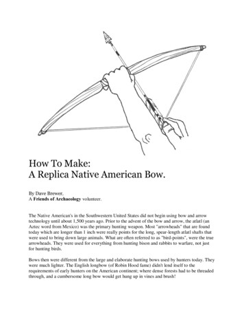
COMPOUND BOWUSER’S GUIDECOMPOUND BOW TERMINOLOGYTOPLIMBBAND(S)TOP CAM (HYBRID DUAL CAM MODELS- SHOWN)or IDLER WHEEL (SINGLE CAM MODEL)*BOW QUIVERHANGARAXLETOPLIMB(S)BOW QUIVERHOOD AND FOAMTOP LIMBPOCKETSPEED NOCKS*TOPLIMBBOLTARROWSARROWCLIPSIGHTPEEP SIGHTCABLE SLIDE,ROLLERGLIDE OR AIRGLIDE (CARBON AIR)SIGHTPINSCABLE GUARD RODOR FLEXSLIDE*QUIVER BRACKETAND QUICK-MOUNT*TUNINGALIGNMENT MARK(Only on certain models)ARROW SHELFCABLE GUARDADJUSTMENT SCREWNOCK LOOPARROW RESTCABLE CLAMP*(FALL-AWAY RESTS ONLY)BOWSLINGGRIPSTRING STOPPERBACKSTOP *ADJUSTMENTSCREWRISER OR HANDLESTABILIZERBOTTOMLIMB BOLTARROW VANEor FLETCHINGBOTTOM AXLEBOTTOM CAMBOTTOMLIMBSBOTTOMLIMB BAND(S)ARROW NOCKMODULEPOSITION HOLESDRAW STOPAND POSITION HOLES* DEPENDS ON BOW MODELPAGE5
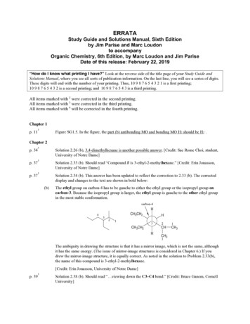
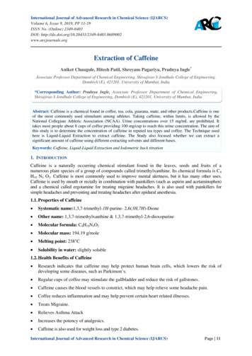
COMPOUND BOWUSER’S GUIDECABLE CONFIGURATIONSONE CAM BOWIDLER WHEELSTRINGSTRINGBUSS CABLEBUSS CABLESTRINGSTRINGBOTTOM CAMHYBRID CAM BOWTOP OLCABLEBOTTOM CAMTWO CAM BOWTOP EBOTTOM CAMPAGE6
COMPOUND BOWUSER’S GUIDEPSE X TECHNOLOGYPSE X Technology bows come with many unique features that will enhance yourarchery experience.USING A BOW PRESS WITH X TECHNOLOGY BOWSALL PSE X Technology bows MUST be serviced in an approved bow press and require specialconsideration. Do not attempt to service these bows in any bow press without reviewing theprocedures described herein.Use of a non-approved bow press or improper use of an approved bow press WILL resultin damage to the bow and possible personal injury. Damages incurred by improper useor maintenance will not be covered under the warranty. See the PSE website atwww.pse-archery.com for a list of approved bow presses.There are two basic types of approved presses available: compression-typeand pull-type. (Pg8)COMPRESSION-TYPE BOW PRESS: (PREFERRED)This type of press pushes in a horizontal direction against the tips of the limbs.No other support for the bow is required.When using a press of this type, back each limb bolt out the maximum number of turnsindicated on your bow’s hang tag. Position the bow in the press and crank press inward toapply a compression force against the limb tips as shown below.COMPRESS ONLY FAR ENOUGH TO LOOSEN THE STRING AND CABLES.OVER COMPRESSING COULD BREAK THE LIMBS AND CAUSE PERSONALINJURY.ANY DAMAGES INCURRED FROM OVER-COMPRESSING WILL NOT BECOVERED UNDER WARRANTY.COMPRESSION-TYPE BOW PRESSX Technology continued on next pagePAGE7
COMPOUND BOWUSER’S GUIDEPSE X TECHNOLOGYUSING A BOW PRESSPULL-TYPE BOW PRESSPULL-TYPE BOW PRESS:This type of press pulls the riser of the bow in a vertical direction betweenrollers that compress the limbs.When using this type press it is very important to position the rollers andpressure points correctly! See illustration above.Back each limb bolt out the maximum number of turns indicated on your bow’s hang tagand position the pressure points on the riser as close to the limbs as possible WITHOUTmaking contact with the limbs as shown in the photo below.THE PRESSURE POINTS MUST NOT CONTACT THELIMBS AT ANY TIME DURING SERVICING.PULL-TYPE BOW PRESSPAGE8X Technology continued on next page
COMPOUND BOWUSER’S GUIDEPSE X TECHNOLOGYUSING A BOW PRESS (Continued)Position the limb rollers outward on the limbs so that when the riser is pulled downthe bow does not slip through/between the rollers before releasing tension on thestring and cables. The rollers must be at least 4” from the limb pockets or the limbswill break. While placing tension on the limbs, BE VERY CAREFUL NOT TO PULL THE RISERDOWN TOO FAR. DEFLECT THE LIMBS JUST ENOUGH TO REMOVE THE STRING ANDCABLES. Never allow the rollers to go past the end of the limb belly (thinnest part).Service such as peep and string mounted vibration damper installation and string replacementcan be performed with a “Pocket Press” portable bow press available from your local PSEdealer. These pocket presses are available for a variety of axle-to-axle lengths and cam types.SERVICING BOWS WITH PSE FT CAMS (PSE FULL THROTTLE )CAUTION CAUTION CAUTION!When servicing bows with PSE FT cams, such as theFull Throttle , it is important to use a bow pressthat has enough clearance for the cams.On some bow presses the cams may makecontact with the area shown in Figure 1 whencompressing the limbs. Watch very carefully as thebow is compressed. If either cam comes in contactwith the bow press, STOP IMMEDIATELYor permanent damage to bowcomponents may occur.Contact the bow press manufacturer forfurther information.Cam mayhit hereFigure 1PAGE9
COMPOUND BOWUSER’S GUIDEINSTALLATION OF ACCESSORIESArrowrest/Overdraw: The arrowrest or overdraw should beinstalled according to the instructions received with the product.It is usually mounted to the riser in the threaded hole on theside opposite the shelf (Hole “A”) using the hardware providedwith the arrowrest or overdraw.Sight: The sight should be installed according to the instructionsreceived with the product. It is usually mounted to the riser inthe threaded holes (Holes “B”) on the side opposite the shelfusing the hardware provided with the sight. Some bows areequipped with multiple sight mounting holes which allow thesight to be moved up or down.Stabilizer: The stabilizer should be mounted according to themanufacturer’s recommendation. It is usually mounted in thethreaded hole on the front of the riser (Hole “C”).HolesBHoleABow Sling: The bow sling attaches to the riser of the bowgenerally with the stabilizer. If a stabilizer is not used, attach thesling to the riser with the correct sized bolt (5/16” - 24) usingthe hole provided for the stabilizer (Hole “C”).OTHER ADJUSTMENTSDraw Weight: Your bow is factory-set to within 2 lbs.of the peak draw weight indicated on the bow hang tag and thelast 2 digits of the serial number. Changes in draw weight canbe made by turning the limb bolt in or out. Before making anychanges in weight, turn the limb bolt clockwise to the bottomposition. Never use extreme torque when turning the bolt ordamage to the limb may occur. The limb bolt may then beturned counterclockwise to obtain the desired weight, but NEVERmore than the number of turns indicated on the hang tag.Adjust each limb exactly the same. (See note and Fig. A below)HoleCLimbboltFig. APocket tanglocking screwLimbsupportscrewCAUTION: On some bow models,the limb bolt locking screw, limbsupport screws or pocket tanglocking screw MUST be loosenedBEFORE adjusting.Your Authorized PSE Dealer is supplied with technical information on PSE bowsand cams. Please see your Dealer for assistance when making these adjustments.PAGE10
COMPOUND BOWUSER’S GUIDESETTING-UP YOUR BOWNOCKING POINT PLACEMENT:Arrow rest mounting holeTuningMarkFinger shooters: Install the nocking point so that the arrowpasses the center of the arrow rest mounting hole andruns slightly point-down relative to the tuning mark on thewindow of the bow.Release Aid shooters: Install the nocking point so thatthe arrow passes the center of the arrow rest mountinghole and runs parallel to the alignment mark on thewindow of the bow.ARROW REST ADJUSTMENT:When shooting with a release aid, the in/out positionof the arrow rest should be adjusted so that the arrowruns parallel with the tuning mark on the shelf whenviewed from above. When shooting with fingers thearrow should point slightly outside the tuning alignmentmark on the shelf.TuningMarkNOTE: Tuning alignment marks are for referenceonly. Adjustments will likely be necessary tonocking point and in/out position during tuningAlignmentMarkSIGHT ADJUSTMENT:When adjusting the sight pin locations, always rememberto “follow the group”. That is, if the shot group is to theleft of the target, move the sight pins to the left. If the shotgroup is low, move the sight pins down. CABLE GUARD ADJUSTMENT AND INSTALLATION:Install the cable guard as shown in Figure A. Adjust the cable guard sothe cables just clear the arrow vanes. On bows using an offset cableguard rod, adjustments must be done with the rod in the up position(2 o’clock) as shown in Figure B (10 o’clock for left handed bows).TRS CABLE GUARD INSTALLATION:Install TRS (Torque Reduction System) as shown.Tighten or loosen adjustment screw until desiredcable clearance is obtained. Tighten the Lock-DownScrew to lock into place. (TRS will only work on bowrisers equipped with the machined in Flex-Slidefeature.)Figure ATRS Adjustment ScrewTRS Lock-Down ScrewTo Adjust: Loosen Lock-Down screw, TurnAdjustment screw, the retighten Lock-Down Screw.PAGE11
COMPOUND BOWUSER’S GUIDEFLEXSLIDE 2 ADJUSTMENT & INSTALLThe PSE FlexSlide 2 cable guard system is basedon the same advanced design used to create PSELimbs. The flex-tuned design and adjustable offset areengineered to create more consistent lateral loadsthrough the draw cycle and improve bow accuracy.1. The standard factory setting adjusts theFlexSlide 2 to its bottom positionfor maximum arrow clearance.2. To adjust the lateral position, turn theadjustment screw counterclockwise toreduce arrow clearance or clockwise toincrease arrow clearance.3. After making adjustments to yourFlexSlide 2 , check botharrow clearance and BackStop clearance.When drawing the bow, the buss cableshould never contact the arrow shaft orany part of the Backstop .4. If any contact exists, tighten theadjustment screw to create adequateclearance. One full turn on the adjustmentscrew will move the slide approximately 1/8”.Only tighten until the section of the FlexSlide 2under the screw head touches the riser.DO NOT OVERTIGHTEN.NOTE: Lateral adjustments to the FlexSlide 2may affect arrow tuning.BACKSTOP INSTRUCTIONSNote: Some PSE Pro Series and Mainline bow models come from the factory with the Backstop 4 or Backstop 3 installed. These instructions refer to reinstallation or adjustment if needed aftermaking adjustments1. Install the BackStop 4 or BackStop 3 into the threaded hole below thegrip on the string-facing side of the bow.2. Adjust the rotator until it makes contact with the string. Mark the string ¼”above and ¼” below where it makes contact with the string. Remove Backstop and add serving to that area of the string if it does not already exist. Reinstall theBackstop .3. Securely tighten the base to the bow handle using the cross-drilled hole.4. Adjust the Backstop 4 or Backstop 3 by rotating and sliding in and out to thedesired position. Tighten the rotator screw. The Backstop 4 and Backstop 3 designsallows for the bumper to be positioned so the string strikes the center of the bumper.It is desired to have some clearance (approximately 1/16”) between the bumperand the bowstring at brace. Once alignment is set, add a small drop of instant glue tolock orientation.Lateral AdjustmentsServe stringin this area.1/16”PAGE12Rotational Adjustments
COMPOUND BOWUSER’S GUIDEBACKSTOP 4 INSTRUCTIONS (CONT.)Note: The Backstop 4 adjusts like the Backstop3 but is enhanced with a grooved rubberstring stop to better stop the string.Backstop 4Serve stringin this area.Rotational AdjustmentsSTING STOP INSTRUCTIONSNote: Several PSE bow models come from the factory with the PSE Sting Stop Backstop installed. These instructions refer to reinstallation or adjustment ifneeded after making adjustments to your PSE bow.1. Thread the Sting Stop nut all the way up toward the bumper of the Sting Stop rod.2. Thread the Sting Stop rod into the threaded hole below the grip on the riser. Thebowstring will need to be displaced slightly to one side to thread the rod into the bow.3. Unscrew the Sting Stop until the rubber bumper approaches the bowstring. Mark thestring 1/4” above the rubber bumper in its highest position and 1/4” below the bumperin its lowest position. Remove the Sting Stop and add serving to the marked area of thestring if it does not already exist. Reinstall the Sting Stop .4. Adjust the Sting Stop to the desired position andtighten the Sting Stop nut against the riser. TheSting Stop design allows for the bumper to bepositioned so the string strikes the center of thebumper. It is desired to have some clearanceServe stringin this area.(approximately 1/16”) between the bumper andthe bowstring at brace. It is preferred to havethe Sting Stop rod in the up position if possible,but may not be possible in order to achieve thenecessary clearance and contact point.PAGE13
COMPOUND BOWUSER’S GUIDEINSTALLING SHOCK MODZ LIMB DAMPERSShock-Modz can be installed in four (4) different orientations between the top and bottomsplit limbs.Into first limb channel and then flex the Shock-Modz to align into the opposit channel.Be sure to position the Shock-Modz at least 1/2” away from the cam.PHOTOS NEEDEDINSTALLING LIMB BAND DAMPERIf your split limb bow is equipped with limb bands, the proper placement of thebands is at least 1/2” away from the cam.Limb Band DamperLimb Band onSolid LimbPAGE14Limb Bands acrossSplit LimbLimb Bands onSplit Limb (one per limb)
COMPOUND BOWUSER’S GUIDEPSE ASYMMETRIC IDLERPSE single cam bows are equipped with a specialasymmetric idler wheel, which is assembled on thetop limbs. It is essential that the idler beoriented properly.Wide edgeThe wide edge of the idler always goes to thecable guard side of the bow.The illustration shows the proper orientation ofthe idler for a right-handed bow when viewed whileholding the bow as it is shot.THE PSE WEBSITE IS YOUR RESOURCEFOR EVERYTHING WE HAVE TO OFFER!www.pse-archery.comPAGE15
COMPOUND BOWUSER’S GUIDEWEDGE LOCK POCKET LAS (LATERAL ADJUSTMENT SYSTEM)FOR XPRESSION, XPRESSION 3D, SUPRA EXT & BEAST EXTThe LAS utilizes pull-system based tuning adjustments. To adjust it, simply loosen the drivescrew on one side of the riser and tighten the drive screw on the other side of the riser tomove the limb bolt.FIGURE 1:When paper tuning your bow and adjustingit for a left or right paper tear, move theLAS in the same direction that you wouldmove your arrow rest if you were adjustingthat.TO TUNE OUT A LEFT TEAR, ADJUST THELAS TO THE RIGHT. TO TUNE OUT A RIGHTTEAR, ADJUST THE LAS TO THE LEFT.To move your tear to to the right, loosenthe left drive screw as seen in FIGURE 1,and then tighten the right drive screw asseen in FIGURE 2. Continue to adjust untilyour paper tuning results in a clean “bullethole” without left or right tears. To moveyour tear to the left, reverse the process byloosing the right drive screw and tighteningthe left drive screw.FIGURE 2:NOTE: The LAS system can be used inconjunction with yoke tuning and arrow resttuning as the shooter sees fit. Also, one orboth Wedge Lock Pockets can be adjustedat a time. Adjusting one pocket at a timeallows for finer tuning, while adjustingboth at the same time will allow for largerchanges.MICRO-LAS (SINGLE SCREW ADJUSTMENTS)Install microLAS (Lateral Adjustment System) as shown. Make sure all set screws are lockeddown tight. When finished, the adjustment screw should not turn too freely or be too tight.When installed correctly, it should take a bit of resistance to turn the screw in either directionwith no play in the system. To Adjust: Turn Adjustment Screw clockwise/counter-clockwise toadjust lateral position of the pocket to help with left/right bow tuning.Adjustment ScrewPAGE16
COMPOUND BOWUSER’S GUIDEECS CAM ADJUSTMENTSTo change draw length on the ECS: Loosen the two 8-32 size 15 Torx screws holding theModule to the Cam approximately 1 ½ turns, move the module to the desired setting. Thesetting will be in the window marked “DL” Move the Module to the same setting on both topand bottom Cams.To change Let-off and the ECS: Loosen the 4-40 size 10 Torx screw holding the Stop on theModule approximately 1 ½ turns and slide to the desired position. Move the Stop to thesame setting on both top and bottom Modules. There are 3 settings, each corresponds toa change in Let-off of 5%. The standard Module Let-off options are 80,85 and 90%. Anaftermarket low let-off Module is available with let off settings of 65,70 and 75%.PAGE17
COMPOUND BOWUSER’S GUIDECAM ADJUSTMENTSWHEELS/CAMS: Many PSE wheels and cams have adjustable features. Each one comes fromthe factory set up and ready to use but there may be occasions that you need to adjust thecharacteristics of your bow. In some cases you will need a PSE Tune Chart to determine whatto adjust, and you may need to see a PSE Dealer for information. If you are not sure of theadjustment you are making, stop and see your PSE Dealer for assistance. In some cases, anappropriate bow press will be needed to make adjustments to cams and wheels. If you do nothave an appropriate press, see your PSE Dealer.CAM ORIENTATION:On cams with orientation marks, a reference mark is found to indicate an approximateorientation. This line is for reference only is meant to give approximate orientationonly and may vary between bow models. The orientation of the cams may be changed slightlyby twisting or untwisting the string or cables.ALL INNER-CAMS:The inner-cam system allows draw length adjustments over a prescribed range usually withoutputting the bow in a bow press. There are two types of inner-cam systems: discrete settinginner-cams and Posi-Lock inner-cams.Discrete setting inner-cams have the adjustment screws going through a specific hole in theinner-cam and threading into the cam. The screws need to be completely removed to makeadjustments. The “A” setting is the longest draw length for that bow and draw lengths getshorter as you progress through the alphabet (A to B, B to C, etc.)Posi-lock adjustable inner-cams are adjustable in ½” draw length increments. The “A” setting isthe longest setting for the cam. Draw lengths get shorter as you progress through the alphabet(“A” to “B”, “B” to “C”, etc.) by roughly ½” per letter.Second and third generation Posi-lock inner-camsallow for draw length adjustments in ½” incrementswithout changing inner-cams. To adjust draw length,loosen the two 8-32 button head screws two fullturns. This will allow the inner-cam to be lifted farenough to disengage the positioning pin and allowthe inner-cam to rotate to a new position. Somecams may require the 8-32 button head screws tomove to alternate locations to reach the new drawlength adjustment position. Some draw lengthadjustment positions may not be accessible withoutputting the bow in a bow press. When the newdraw length adjustment position has been achievedwith the inner-cam, tighten the two 8-32 buttonhead screws and move the draw stop to thematching setting (“A” and “A”, “B” and “B”).Positioning Pin8-32 Button Head ScrewIn cases where there is an inner-cam on both the top and bottom cam, both cams must beset in the same letter position for the bow to tune and shoot properly. In cases where thereis a separate draw stop, the draw stop must be moved to the hole marked with the lettercorresponding to the inner-cam setting.PAGE18
COMPOUND BOWUSER’S GUIDEINFORMATION ON DRAW STOP ADJUSTMENTS:The position of the draw stop must match the setting on the inner-cam. For example, if the cam is set on “E”, the drawstop must be placed in one of the draw stop holes marked with an “E”. If the inner-cam is in the “B” setting, the stopmust be in the “B” position. Certain hybrid cams have top and bottom stops. They can be shot with both stops for aharder “wall” or with only the top stop for a softer “wall”. Never shoot hybrid cams with the two stop option with only thebottom stop. In either case, the stops need to be in the holes marked with the same marking as the inner-cam setting.Draw StopScrewDraw StopLIMB STOP ADJUSTMENTSOn bows equipped with a limb stop and cable stop, use of the limb stop is optional. Ifchoosing not to use the limb stop it may be removed or set in the longest “A” position sothat it does not contact the limb before the cable stop. Engraving for limb stop positions isapproximate and for reference only. Many factors will cause changes to the optimum limbstop position.OPTION 1: (If a safe method of holding the bow at full draw is available, such as a drawboard) Set Limb Stop to the Longest “A” Location and time bow to cable stops at desireddraw length as shown in Figure 1. Using a safe method to hold the bow at full draw adjustlimb stop so it contacts the limb as shown in Figure 2.FIGURE 1FIGURE 2OPTION 2: Set Limb Stop to the Longest “A” Postition. Time bow to cable stops at desireddraw length.Set Limb stop to the corresponding stop position. Draw bow with an arrow,pointed at a safe range or target and observe whether the cable stop or Limb Stop contactsfirst. Make small adjustments to the Limb Stop position and recheck until it contacts atthe same time as the cable stop.PAGE19
COMPOUND BOWUSER’S GUIDEPSE PRO SERIES BOWS:DRAW SETTING CHARTNOTE: The PSE Full Throttle has cam-specific draw lengths from 26-1/2” to 30” in 1/2” increments.SETTINGCARBON AIR34CARBON AIR32 HLCARBON AIR32 HDFULLTHROTTLEEVOLVE 35EVOLVEDECREE 32A31 1/23030 1/2NA31 1/23030 1/2B3129 1/230NA3129 1/230C30 1/22929 1/2NA30 1/22929 1/2D3028 1/229NA3028 1/229E29 1/22828 1/2NA29 1/22828 1/2F2927 1/228NA2927 1/228G28 1/22727 1/2NA28 1/22727 1/2H2826 1/227NA2826 1/227I27 1/22626 1/2NA27 1/22626 1/2J2725 1/226NA2725 1/226K26 1/22525 1/2NA26 1/22525 1/2L2624 1/225NA2624 1/225M--24 1/2NA--24 1/2SETTINGDECREE 35BEAST EXTINERTIADRIVE R DCDRIVE R SDVENDETTAVXA31 1/2333030 1/22830 1/2B3132 1/229 1/230
Position the bow in the press and crank press inward to apply a compression force against the limb tips as shown below. COMPRESS ONLY FAR ENOUGH TO LOOSEN THE STRING AND CABLES. OVER COMPRESSING COULD BREAK THE LIMBS AND CAUSE PERSONAL INJUR