Transcription
68012010008 ca.book Page 1 Wednesday, July 19, 2017 3:59 PMMINITOR VIAMPLIFIER CHARGERRLN6506en-USfr-CA
68012010008 ca.book Page 2 Wednesday, July 19, 2017 3:59 PM
68012010008 ca.book Page 1 Wednesday, July 19, 2017 3:59 PMIMPORTANT SAFETY INSTRUCTIONSThis document contains important safety and operating instructions. Please read these instructionscarefully and save them for future reference.Before using the battery charger, read all the instructions and cautionary markings on (1) the charger, (2) thebattery, and (3) on the pager using the battery.WARNINGSWARNING1.To reduce risk of injury, charge only the rechargeable Motorola Solutions-authorizedbatteries listed in Table 1. Other batteries may explode, causing personal injury ordamage.2.Use of accessories not recommended by Motorola Solutions may result in risk of fire,electric shock, or injury.3.To reduce risk of damage to the electric plug and cord, pull by the plug rather than thecord when disconnecting the charger.4.An extension cord should not be used unless absolutely necessary. Use of an improperextension cord could result in risk of fire or electric shock. If an extension cord must beused, make sure that the cord size is 18 AWG for lengths up to 100 feet (30.48 m) and16 AWG for lengths up to 150 feet (45.72 m).5.To reduce risk of fire, electric shock, or injury, do not operate the charger if it has beenbroken or damaged in any way. Take it to a qualified Motorola Solutions servicerepresentative.1English
68012010008 ca.book Page 2 Wednesday, July 19, 2017 3:59 PMWARNINGS (CONTINUED)WARNING6.Do not disassemble the charger; it is not repairable and replacement parts are notavailable. Disassembly of the charger may result in risk of electrical shock or fire.7.To reduce risk of electric shock, unplug the charger from the AC outlet before attemptingany maintenance or cleaning.8.To reduce risk of injury, use charger with Motorola Solutions authorized power supplieslisted in Table 2.9.This is a Class A product. In a domestic environment, this product may cause pagerinterference in which case the user may be required to take adequate measures.OPERATIONAL SAFETY GUIDELINES This equipment is not suitable for outdoor use. Use only in dry locations/conditions.Ensure the pager is dry before inserting into the Amplifier Charger.Connect equipment only to an appropriately fused and wired supply of the correct voltage (as specified onthe product). Disconnect from line voltage by removing main plug.The socket outlet to which this equipment is connected should be close by and easily accessible.In equipment using fuses, replacements must comply with the type and rating specified in the equipmentinstructions.Maximum ambient temperature around the power supply equipment must not exceed 40 C (104 F).Output power from the power supply unit must not exceed the ratings stated on the product label locatedon the bottom of the charger.Make sure the cord is located where it will not be stepped on, tripped over, or subjected to water, damage,or stress.English2
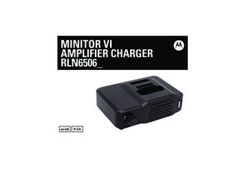
68012010008 ca.book Page 3 Wednesday, July 19, 2017 3:59 PMBRIEF DESCRIPTIONThe Amplifier Charger is intended for use with the Motorola Solutions -approved Lithium-ion rechargeablebatteries (listed in Table 1). The front pocket of the charger is capable of handling a pager with an attachedbattery. The rear pocket is designed only to charge the above mentioned batteries (alone).An illuminated LED indicates the state of charge for the front and rear pocket.OPERATIONAL GUIDELINES Always remember to power the Amplifier Charger first before inserting the pager with the attached batteryinto the front pocket or the auxiliary battery into the charger's rear pocket.The front pocket has charging priority over the rear pocket. Therefore, the rear pocket may not charge atits full rate until the front pocket charging is complete.The Amplifier Charger is not designed to accommodate the alkaline battery tray.MOTOROLA SOLUTIONS-AUTHORIZED BATTERIESThe batteries listed in Table 1 is approved for use with the Amplifier Charger.Table 1: Motorola-Authorized BatteriesKit (Part) NumberPlatform/DescriptionPMNN4438Battery, Li-Ion (UL Battery)PMNN4451Battery, Li-Ion (Non-UL Battery)Note: The Amplifier Charger is not designed to accommodate the alkaline battery tray.3English
68012010008 ca.book Page 4 Wednesday, July 19, 2017 3:59 PMMOTOROLA SOLUTIONS-AUTHORIZED POWER SOURCES/POWER SUPPLIESThe power supply listed in Table 2 is approved for use with the Amplifier Charger.Table 2: Motorola Solutions-Authorized Power SupplyPower SupplyKit NumberDescriptionEPNN9288ASwitch Mode PS, NA, LAMOTOROLA SOLUTIONS-AUTHORIZED ANTENNASThe antennas listed in Table 3 is approved for use with the Amplifier Charger.Table 3: Motorola Solutions-Authorized AntennasKit (Part) NumberPlatform/DescriptionRLN6507Antenna, Charger AMP, MIN VI VHFRLN6508Antenna, Charger AMP, MIN VI UHFMOTOROLA SOLUTIONS-AUTHORIZED CHARGERTable 4: Motorola Solutions Authorized ChargerEnglishCharger KitNumberCharger DescriptionPMLN6465Amplifier Charger Base4
68012010008 ca.book Page 5 Wednesday, July 19, 2017 3:59 PMSTANDARD FEATURESExternal AntennaThe external antenna input jack (BNC connector) is located on the rear of the Amplifier Charger housing. Anexternal antenna must be attached to the Amplifier Charger for maximal reception.Audio AmplifierThe Amplifier Charger contains a 2.5 watt audio amplifier and speaker. When a pager is placed in theAmplifier Charger, the audio is routed to the Amplifier Charger speaker rather than to the pager speaker.External Speaker JackAn external speaker jack, located on the rear of the Amplifier Charger housing, allows the user to attach anexternal speaker. When an external speaker is connected, audio will be routed to that speaker rather than tothe Amplifier Charger internal speaker. The minimum speaker impedance is 4 ohms.RelayThe Amplifier Charger includes a relay that is energized whenever an alert is received, and a 6-pin DINaccessory connector is located on the rear of the unit. The 6-pin mating plug for these models may be wiredto provide the following functions: Remote Speaker Audio (Pins 1 and 6)An external 4-ohm speaker may be connected to the Amplifier Charger via pin 1 (audio) and pin 6 (groundreturn) of the plug, to provide both remote speaker audio and internal speaker audio at the same time. Relay Dry Contact Closure (Pins 2 and 3)When the accessory relay is energized, its contacts close and present a short across pins 2 and 3 of theconnector. The relay contacts are rated for 10 watts maximum at 28 VDC/ACRMS. Within the limits of the5English
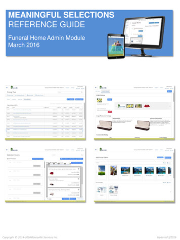
68012010008 ca.book Page 6 Wednesday, July 19, 2017 3:59 PM 10-watt rating the closed contacts can handle up to 750 mA continuously and switch up to 400 mA ofcurrent. Relay contact rating: 750 mA maximum @ 28 VDC.Relay Closure Timing Control (Pins 4 and 5)Accessory connector, pins 4 and 5, are used to select the time duration of the relay contact closure. Ifthese two pins are not used (open circuit), the relay remains energized for approximately 10 seconds afteran alert is received or until the reset button is pressed, whichever comes first. If pins 4 and 5 are shorted,the relay remains energized until the reset button on the front of the Amplifier Charger is pressed.Pressing the reset button causes the contacts to open to turn off the ALERT indicator.ACCESSORYPIN 6Ground (Audio)PIN 1AudioPIN 3Relay Dry ContactPIN 4Relay Closure TimingPIN 5Relay Closure TimingPIN 2Relay Dry ContactFigure 1: Overview of the 6-Pin DIN Accessory ConnectorEnglish6
68012010008 ca.book Page 7 Wednesday, July 19, 2017 3:59 PMOPERATING INSTRUCTIONSAmplifier Chargers are intended for use only with the authorized Motorola Solutions batteries andpower supplies listed in Table 1 and Table 2; usage with unauthorized products may prevent properoperation and may damage the device.The battery charger will accommodate a pager with an attached battery in the front pocket, and a batteryalone in the rear pocket. To charge a battery, use the following procedure:1.Plug the round end of the power supply cord into the DC Connector on the back of the charger.2.Plug the power supply into the appropriate AC outlet. The spare battery LED and pager battery LED willflash single green once and the alert LED will flash single red once to indicate a successful power-up.3.Insert a pager with battery into the charger's front pocket by:a. aligning the groove on each side of the pager with the corresponding raised rail on each side of thecharger pocket.b. sliding the pager into the charger pocket, ensuring complete contact between the charger and pagercontacts.4.When the pager is properly seated in the pocket, the charger LED will light in accordance with Table 5 onpage 10.Note: Charge new batteries overnight to ensure full charge. To minimize charge time, it is recommended to turnthe pager OFF. The Amplifier Charger is not designed to accommodate the alkaline battery tray. During receipt of a page, the LED may flash amber, indicating charging has temporarily been suspended.7English
68012010008 ca.book Page 8 Wednesday, July 19, 2017 3:59 PM5.Insert a battery into the charger’s rear pocket by:a. aligning the groove on each side of the battery with the corresponding raised rail on each side of thecharger pocket.b. sliding the battery into the charger pocket, ensuring complete contact between the charger andbattery contacts.6.When the battery is properly seated in the pocket, the charger LED will light in accordance with Table 5on page 10.Note: Charge new batteries overnight to ensure full charge. The Amplifier Charger is not designed to accommodate the alkaline battery tray.English8
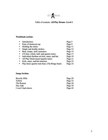
68012010008 ca.book Page 9 Wednesday, July 19, 2017 3:59 PMRear PocketSpareBattery LEDFrontPocketPagerBattery LEDAlertLEDVolumeKnobResetButtonSpeakerFrontDC torRearFigure 2: Amplifier Charger9English
68012010008 ca.book Page 10 Wednesday, July 19, 2017 3:59 PMTROUBLESHOOTINGWhen troubleshooting, always observe the color of the LED:Table 5: Charger StatusLED IndicationCharger StatusCharger Successfully Powered Up and IsReady for UseSingle Flash GreenPre-ChargeSlow Flash AmberBattery under-voltage recovery.Under-Voltage Recovery Timeout(15 Minutes)Fast Flash RedLoss of Charge Current Control(Difference Between Command andFeedback Electrical Tolerance Analysis)Excessive Power Supply VoltageFault.Fast Charge or Charge Ramp DownSteady RedEnglishNormal operation.10
68012010008 ca.book Page 11 Wednesday, July 19, 2017 3:59 PMTable 5: Charger Status (continued)LED IndicationCharger StatusNearly ChargedNormal operation.Slow Flashing GreenThe battery is charged to at least the 90%threshold programmed into the battery. Or, ifthe battery lacks an internal memory device,the charging current has ramped down to avalue less than a charger default threshold.Charged or Nearly ChargedNormal operation.Steady GreenThe battery is charged to at least the 95%threshold programmed into the battery. Or, ifthe battery lacks an internal memory device,the charging current has ramped down to avalue less than a charger default threshold.Thermistor OpenNo battery in pocket.OffBattery OpenFast Flash RedBattery– OpenorFast FlashRedFault.OffAppears like Battery Open orThermistor Open.11English
68012010008 ca.book Page 12 Wednesday, July 19, 2017 3:59 PMTable 5: Charger Status (continued)LED IndicationCharger StatusThermistor Short to GroundFast Flash RedFault.Thermistor Short to Battery Appears like Thermistor Open for mostbattery voltages, ororOffSlow FlashAmberAppears like Cold Battery for discharged ornearly-discharged batteries.Battery and Battery– ShortFast Flash RedFault.Temperature Approximately 5 C(or Value Programmed in Battery)Slow Flash AmberWait to charge — battery too cold.Temperature Approximately 45 C(or Value Programmed in Battery)Slow Flash AmberEnglishWait to charge — battery too hot.12
68012010008 ca.book Page 13 Wednesday, July 19, 2017 3:59 PMTable 5: Charger Status (continued)LED IndicationCharger StatusNote: Applicable to the battery pocket only ifthe pocket prioritization feature is used.Steady AmberThe Pocket is Waiting for ChargingCurrent to be AvailableWait to charge — charging will begin whencurrent is made available by the higherpriority pocket or device.If There is No LED Indication:1.Check that the pager with battery is inserted correctly in the front pocket or the battery in the rear pocket.2.Make sure that the transformer is plugged into an appropriate AC outlet.3.Ensure that the transformer cable is plugged securely into the charger socket.4.Confirm that the battery being used with the pager is listed in Table 1 on page 3.SERVICEDo not disassemble the Amplifier Charger; it is not repairable. Order replacement antennas (listed in Table 3on page 4) or power supplies (listed in Table 2 on page 4) as necessary.13English
68012010008 ca.book Page 14 Wednesday, July 19, 2017 3:59 PMCHARGERS WARRANTYThe Workmanship WarrantyThe workmanship warranty guarantees against defects in workmanship under normal use and service.ChargersOne (1) YearLIMITED WARRANTYMOTOROLA SOLUTIONS COMMUNICATION PRODUCTSI. WHAT THIS WARRANTY COVERS AND FOR HOW LONG:MOTOROLA SOLUTIONS, INC. (“MOTOROLA”) at its option, will at no charge either repair the Product (withnew or reconditioned parts), replace it (with a new or reconditioned Product), or refund the purchase price ofthe Product during the warranty period provided it is returned in accordance with the terms of this warranty.Replaced parts or boards are warranted for the balance of the original applicable warranty period. Allreplaced parts of Product shall become the property of MOTOROLA.This express limited warranty is extended by MOTOROLA to the original end user purchaser only and is notassignable or transferable to any other party. This is the complete warranty for the Product manufactured byMOTOROLA. MOTOROLA assumes no obligations or liability for additions or modifications to this warrantyunless made in writing and signed by an officer of MOTOROLA.Unless made in a separate agreement between MOTOROLA and the original end user purchaser,MOTOROLA does not warrant the installation, maintenance or service of the Product.MOTOROLA cannot be responsible in any way for any ancillary equipment not furnished by MOTOROLAwhich is attached to or used in connection with the Product, or for operation of the Product with any ancillaryequipment, and all such equipment is expressly excluded from this warranty. Because each system whichmay use the Product is unique, MOTOROLA disclaims liability for range, coverage, or operation of the systemas a whole under this warranty.English14
68012010008 ca.book Page 15 Wednesday, July 19, 2017 3:59 PMII. GENERAL PROVISIONS:This warranty sets forth the full extent of MOTOROLA'S responsibilities regarding the Product. Repair,replacement or refund of the purchase price, at MOTOROLA’s option, is the exclusive remedy. THISWARRANTY IS GIVEN IN LIEU OF ALL OTHER EXPRESS WARRANTIES. IMPLIED WARRANTIES,INCLUDING WITHOUT LIMITATION, IMPLIED WARRANTIES OF MERCHANTABILITY AND FITNESS FORA PARTICULAR PURPOSE, ARE LIMITED TO THE DURATION OF THIS LIMITED WARRANTY. IN NOEVENT SHALL MOTOROLA BE LIABLE FOR DAMAGES IN EXCESS OF THE PURCHASE PRICE OF THEPRODUCT, FOR ANY LOSS OF USE, LOSS OF TIME, INCONVENIENCE, COMMERCIAL LOSS, LOSTPROFITS OR SAVINGS OR OTHER INCIDENTAL, SPECIAL OR CONSEQUENTIAL DAMAGES ARISINGOUT OF THE USE OR INABILITY TO USE SUCH PRODUCT, TO THE FULL EXTENT SUCH MAY BEDISCLAIMED BY LAW.III. STATE LAW RIGHTS:SOME STATES DO NOT ALLOW THE EXCLUSION OR LIMITATION OF INCIDENTAL ORCONSEQUENTIAL DAMAGES OR LIMITATION ON HOW LONG AN IMPLIED WARRANTY LASTS, SOTHE ABOVE LIMITATION OR EXCLUSIONS MAY NOT APPLY.This warranty gives specific legal rights, and there may be other rights which may vary from state to state.IV. HOW TO GET WARRANTY SERVICE:You must provide proof of purchase (bearing the date of purchase and Product item serial number) in order toreceive warranty service and, also, deliver or send the Product item, transportation and insurance prepaid, toan authorized warranty service location. Warranty service will be provided by MOTOROLA through one of itsauthorized warranty service locations. If you first contact the company which sold you the Product (e.g.,dealer or communication service provider), it can facilitate your obtaining warranty service. You can also callMOTOROLA at 1-800-927-2744 US/Canada.V. WHAT THIS WARRANTY DOES NOT COVER:A)Defects or damage resulting from use of the Product in other than its normal and customary manner.15English
68012010008 ca.book Page 16 Wednesday, July 19, 2017 3:59 PMB)Defects or damage from misuse, accident, water, or neglect.C) Defects or damage from improper testing, operation, maintenance, installation, alteration, modification,or adjustment.D) Breakage or damage to antennas unless caused directly by defects in material workmanship.E)A Product subjected to unauthorized Product modifications, disassembles or repairs (including, withoutlimitation, the addition to the Product of non-MOTOROLA supplied equipment) which adversely affectperformance of the Product or interfere with MOTOROLA's normal warranty inspection and testing of theProduct to verify any warranty claim.F)Product which has had the serial number removed or made illegible.G) Freight costs to the repair depot.H) A Product which, due to illegal or unauthorized alteration of the software/firmware in the Product, doesnot function in accordance with MOTOROLA’s published specifications or the FCC certification labelingin effect for the Product at the time the Product was initially distributed from MOTOROLA.I)Scratches or other cosmetic damage to Product surfaces that does not affect the operation of theProduct.J)Normal and customary wear and tear.VI. PATENT AND SOFTWARE PROVISIONS:MOTOROLA will defend, at its own expense, any suit brought against the end user purchaser to the extentthat it is based on a claim that the Product or parts infringe a United States patent, and MOTOROLA will paythose costs and damages finally awarded against the end user purchaser in any such suit which areattributable to any such claim, but such defense and payments are conditioned on the following:A)that MOTOROLA will be notified promptly in writing by such purchaser of any notice of such claim;B)that MOTOROLA will have sole control of the defense of such suit and all negotiations for its settlementor compromise; andEnglish16
68012010008 ca.book Page 17 Wednesday, July 19, 2017 3:59 PMC) should the Product or parts become, or in MOTOROLA’s opinion be likely to become, the subject of aclaim of infringement of a United States patent, that such purchaser will permit MOTOROLA, at its optionand expense, either to procure for such purchaser the right to continue using the Product or parts or toreplace or modify the same so that it becomes non-infringing or to grant such purchaser a credit for theProduct or parts as depreciated and accept its return. The depreciation will be an equal amount per yearover the lifetime of the Product or parts as established by MOTOROLA.MOTOROLA will have no liability with respect to any claim of patent infringement which is based upon thecombination of the Product or parts furnished hereunder with software, apparatus or devices not furnished byMOTOROLA, nor will MOTOROLA have any liability for the use of ancillary equipment or software notfurnished by MOTOROLA which is attached to or used in connection with the Product. The foregoing statesthe entire liability of MOTOROLA with respect to infringement of patents by the Product or any parts thereof.Laws in the United States and other countries preserve for MOTOROLA certain exclusive rights forcopyrighted MOTOROLA software such as the exclusive rights to reproduce in copies and distribute copies ofsuch MOTOROLA software. MOTOROLA software may be used in only the Product in which the softwarewas originally embodied and such software in such Product may not be replaced, copied, distributed,modified in any way, or used to produce any derivative thereof. No other use including, without limitation,alteration, modification, reproduction, distribution, or reverse engineering of such MOTOROLA software orexercise of rights in such MOTOROLA software is permitted. No license is granted by implication, estoppel orotherwise under MOTOROLA patent rights or copyrights.VII. GOVERNING LAW:This Warranty is governed by the laws of the State of Illinois, U.S.A.MOTOROLA, MOTO, MOTOROLA SOLUTIONS and the Stylized M logo are trademarks or registered trademarks of Motorola TrademarkHoldings, LLC and are used under license. All other trademarks are the property of their respective owners. 2013 and 2017 Motorola Solutions, Inc. All rights reserved17English
68012010008 ca.book Page 18 Wednesday, July 19, 2017 3:59 PMNOTESEnglish18
68012010008 ca.book Page 1 Wednesday, July 19, 2017 3:59 PMNOTICE DE SÉCURITÉ IMPORTANTECe document contient d'importantes directives relatives à la sécurité et au fonctionnement del'appareil. Veuillez lire attentivement cette notice et la conserver pour vous y référer ultérieurement.Avant d'utiliser le chargeur de batterie, lisez toutes les directives et les marquages d'avertissement sur (1) lechargeur, (2) la batterie et (3) le téléavertisseur associé à la batterie.AVERTISSEMENTS1.AVERTISSEMENT 2.Afin de réduire les risques de blessure, ne chargez que les batteries rechargeablesagréées Motorola Solutions apparaissant dans le Tableau 1. Les batteries non agrééespourraient exploser et causer des blessures corporelles ou d'autres dommages.L'utilisation d'accessoires non recommandés par Motorola Solutions pourrait occasionnerdes risques d'incendie, de choc électrique ou de blessure.3.Afin de réduire la possibilité d'endommager la fiche et le cordon d'alimentation, débranchez le chargeuren tirant sur la fiche au lieu du cordon.4.Il n'est pas recommandé d'utiliser une rallonge, sauf en cas de nécessité absolue. L'utilisation d'unerallonge inappropriée pourrait causer un risque d'incendie ou de choc électrique. Si une rallonge doit êtreutilisée, assurez-vous que le format du cordon est de calibre 18 lorsque sa longueur est de 100 pieds(30,48 m) ou moins et de calibre 16 lorsque sa longueur est de 150 pieds (45,72 m) ou moins.5.Pour réduire le risque d'incendie, de choc électrique ou de blessure, n'utilisez pas le chargeur s'il estbrisé ou endommagé de quelque manière que ce soit. Apportez-le à un technicien Motorola Solutionsqualifié.1Français Canadien
68012010008 ca.book Page 2 Wednesday, July 19, 2017 3:59 PMAVERTISSEMENTS (SUITE)AVERTISSEMENT6.Ne désassemblez pas le chargeur. Il ne peut être réparé et aucune pièce de rechangen'est disponible. Le désassemblage du chargeur pourrait occasionner des risques dechoc électrique ou d'incendie.7.Pour réduire les risques de choc électrique, débranchez le chargeur de la prise c.a. avantde procéder à une maintenance ou à un nettoyage.8.Pour réduire les risques de blessure, n'utilisez le chargeur qu'avec les blocs d'alimentation agréésMotorola Solutions apparaissant dans le Tableau 2.9.Ce produit est de classe A. Ce produit peut entraîner des interférences dans un environnement résidentiel,auquel cas l’utilisateur peut devoir prendre des mesures adéquates.DIRECTIVES D'UTILISATION SÉCURITAIRE Cet équipement n'est pas conçu pour une utilisation à l'extérieur. Ne l'utilisez que dans des emplacementssecs et sous des conditions de nature semblable.Assurez-vous que le téléavertisseur est sec avant de l'insérer dans le chargeur amplificateur.Ne branchez l'équipement qu'à un bloc d'alimentation à fusible câblé approprié de tension prescrite (telle quespécifiée sur le produit). Débranchez le chargeur de la tension de secteur en retirant la fiche principale.La prise de courant à laquelle cet équipement est branché doit se trouver à proximité et être facilementaccessible.Pour les appareils utilisant des fusibles, les pièces de rechange devront être conformes aux instructionsfournies dans la documentation.La température ambiante maximale autour du bloc d'alimentation ne doit pas dépasser 40 C (104 F).La puissance de sortie du bloc d'alimentation ne devra pas dépasser la puissance indiquée sur l'étiquettedu produit apposée sous le chargeur.Assurez-vous que le cordon est placé à un endroit où il ne sera pas écrasé ou endommagé, ne gênerapas le passage, ne sera pas tendu de façon anormale et ne sera pas exposé à une source d'humidité.Français Canadien2
68012010008 ca.book Page 3 Wednesday, July 19, 2017 3:59 PMDESCRIPTION BRÈVELe chargeur amplificateur est conçu pour être utilisé avec les batteries au lithium-ion rechargeables agréées MotorolaSolutions (indiquées dans le Tableau 1). Le logement avant du chargeur peut contenir un téléavertisseuraccompagné de sa batterie. Le logement arrière est conçu uniquement pour charger les batteries mentionnées cidessus (seules).Un voyant DEL illuminé indique l'état de charge des logements avant et arrière.DIRECTIVES D'UTILISATION Rappelez-vous de toujours allumer le chargeur amplificateur avant d'insérer le téléavertisseur avecbatterie dans le logement avant du chargeur ou la batterie auxiliaire dans le logement arrière.Le logement avant a priorité sur le logement arrière. Il est donc possible que le logement arrière necharge pas à pleine capacité avant que la charge du logement avant ne soit terminée.Le chargeur amplificateur n'est pas conçu pour recevoir un support de batterie alcaline.BATTERIES AGRÉÉES MOTOROLA SOLUTIONSLes batteries répertoriées dans le Tableau 1 sont agréées pour le chargeur amplificateur.Tableau 1 : Batteries agréées Motorola SolutionsNuméro detrousse (pièce)Plateforme/descriptionPMNN4438Batterie, Li-ion (Batterie UL)PMNN4451Batterie, Li-ion (Batterie Non-UL)Remarque : Le chargeur amplificateur n'est pas conçu pour recevoir un support de batterie alcaline.3Français Canadien
68012010008 ca.book Page 4 Wednesday, July 19, 2017 3:59 PMSOURCES ET BLOCS D'ALIMENTATION AGRÉÉS MOTOROLA SOLUTIONSLe bloc d'alimentation indiqué dans le Tableau 2 est agréé pour le chargeur amplificateur.Tableau 2 : Bloc d'alimentation agréé Motorola SolutionsBlocd'alimentationNuméro detrousseDescriptionEPNN9288AMode De Commutation PS, NA, LAANTENNES AGRÉÉES MOTOROLA SOLUTIONSLes antennes répertoriées dans le Tableau 3 sont agréées pour le chargeur amplificateur.Tableau 3 : Antennes agréées Motorola SolutionsNuméro detrousse (pièce)Plateforme/descriptionRLN6507Antennes, Chargeur AMP, VI VHF MINRLN6508Antennes, Chargeur AMP, VI UHF MINCHARGEUR AGRÉÉ MOTOROLATableau 4 : Chargeur agréé Motorola SolutionsFrançais CanadienNuméro de lot duchargeurDescription du chargeurPMLN6465Chargeur Amplificateur Base4
68012010008 ca.book Page 5 Wednesday, July 19, 2017 3:59 PMFONCTIONS STANDARDSAntenne externeLa prise d'entrée de l'antenne externe (connecteur BNC) se trouve à l'arrière du boîtier du chargeuramplificateur. Une antenne externe doit être reliée à l'amplificateur chargeur pour une réception maximale.Amplificateur audioLe chargeur amplificateur contient un amplificateur audio de 2,5 watts et un haut-parleur. Lorsqu'untéléavertisseur est inséré dans le chargeur amplificateur, le son est transmis par le haut-parleur du chargeurplutôt que par celui du téléavertisseur.Prise pour haut-parleur externeUne prise pour haut-parleur externe, située à l'arrière du chargeur amplificateur, permet à l'utilisateur debrancher un haut-parleur externe. Lorsqu'un haut-parleur externe est branché, le son est transmis par celui-ciplutôt que par le haut-parleur interne du chargeur amplificateur. L'impédance minimale du haut-parleur est de4 ohms.RelaisLe chargeur amplificateur comporte un relais qui est alimenté dès qu'une alerte est reçue, ainsi qu'unconnecteur pour accessoire DIN à six broches situé à l'arrière de l'unité. La prise homologue à six broches deces modèles peut être reliée par câble pour offrir les fonctions suivantes : Audio par haut-parleur distant (broches 1 et 6)Un haut-parleur externe de 4 ohms peut être branché au chargeur amplificateur par la broche 1 (audio) etla broche 6 (retour par la terre) afin que le son soit transmis à la fois par un haut-parleur distant et par lehaut-parleur interne. Fermeture des contacts secs du relais (broches 2 et 3)Lorsque le relais est alimenté, ses contacts se ferment et présentent un court-circuit entre les broches2 et 3 du connecteur. Les contacts du relais sont homologués pour 10 watts au maximum à 28 RMS5Français Canadien
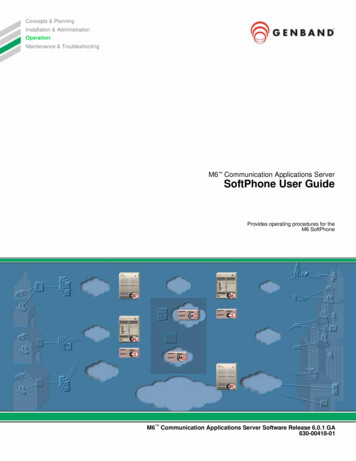
68012010008 ca.book Page 6 Wednesday, July 19, 2017 3:59 PM V C.C./C.A. À l'intérieur des limites de l'homologation de 10 watts, les contacts fermés peuvent recevoirjusqu'à 750 mA en continu et alterner jusqu'à 400 mA de courant. Homologation des contacts du relais :750 mA maximum @ 28 V C.C.Contrôle du minutage de fermeture du relais (broches 4 et 5)Les connecteurs d'accessoire, les broches 4 et 5, permettent de sélectionner la durée de fermeture descontacts du relais. Si ces deux broches ne sont pas utilisées (circuit ouvert), le relais demeure alimenté durantenviron 10 secondes après la réception d'une alerte ou jusqu'à ce que le bouton de réinitialisation soit enfoncé,selon la première éventualité. Si les broches 4 et 5 sont court-circuitées, le relais demeure alimenté jusqu'à ceque le bouton de réinitialisation situé à l'avant du chargeur amplificateur soit enfoncé. L'utilisation du bouton deréinitialisation entraîne l'ouverture des contacts afin d'éteindre l'indicateur d'alerte.ACCESSOIREBROCHE 6Masse (audio)BROCHE 1AudioBROCHE 3Contact sec du relaisBROCHE 4 Minutagede fermeture du relaisBROCHE 5 Minutagede fermeture du relaisBROCHE 2Contact sec du relaisFigure 1 : Aperçu du connecteur DIN à
68012010008_ca.book Page 1 Wednesday, July 19, 2017 3:59 PM. 68012010008_ca.book Page 2 Wednesday, July 19, 2017 3:59 PM. 1 English . the rela y remains energized for approximately 10 seconds after an alert is received or until the reset button is pres