Transcription
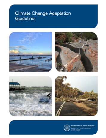
UManagingWildfire RisksUTILITIES AROUND THE WORLD ARE FACING UNprecedented levels of fire risk from routine electrical faults andfailures in transmission and distribution lines and equipment.The risk is elevated by changing weather patterns that produceextreme drought conditions and violent storms. These utilitiesare confronting aging power apparatus and difficult-to-detectfailure and arcing fault scenarios. Major fires in recent yearshave increased public awareness of the risk.San Diego Gas & Electric Company (SDG&E) is amongCalifornia utilities facing this hazard, dealing with its causes,and engaging in major efforts to reduce it. The program of riskreduction is based largely on innovative solutions—experimenting with and implementing a variety of new technologiesand strategies. There is no single approach to firerisk reduction; SDG&E pursues a variety of apparatus upgrading programs and operational andevent responses, as it develops new protection andcontrol equipment and methods.This article presents SDG&E’s range ofstrategies for reducing fire risk, including gridhardening replacements, weather monitoring,adaptive operating procedures, adaptive distribution fault detection and tripping designs, andfaster and more sensitive new transmission lineprotection schemes. In addition, SDG&E hasbeen the industry leader in the development ofdistribution falling conductor protection (FCP)based on phasor measurement units (PMUs)and synchrophasor data streams gathered acrossdistribution circuits.As we explain, detecting a conductor breakand de-energizing a circuit while the conductor is still falling avoids an arcing ground faultthat can ignite dry vegetation—the broken conductor has no power when it lands. SDG&E ispreparing to deploy new transmission line FCPschemes based on PMU measurements, whichcan trip a line and avoid fire ignition risk in thesame way that it does for distribution circuits.We summarize companywide strategies andgive technical specifics for each protection and control strategy in the following sections.Grid Hardening and OperationAdaptations to Reduce RiskSDG&E has developed a broad fire safety enhancementprogram combining fundamental, commonsense upgradeefforts to reduce root causes of risk through new technologies to detect hazardous events at specific locations on thegrid. The company has invested billions of dollars for morethan a decade in the risk assessment and mitigation phase ofits wildfire risk control plan. In this section, we summarizehighlights of that implementation plan.Digital Object Identifier 10.1109/MPE.2021.3122733Date of current version: 19 January 202264IEEE power & energy magazine1540-7977/22 2022IEEEjanuary/february 2022
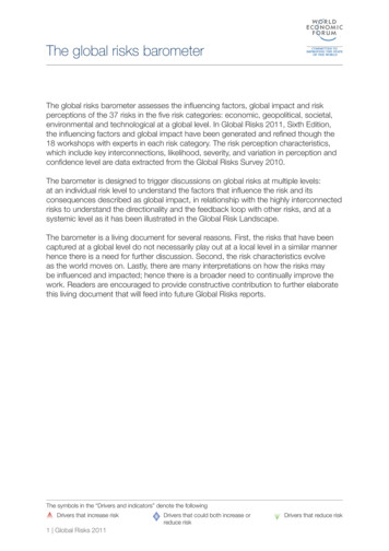
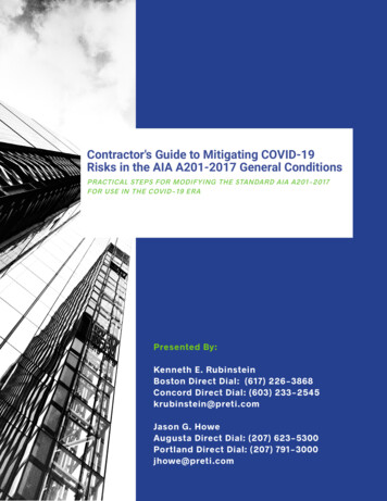
By Eric A. Udren, Chris Bolton, Dan Dietmeyer,Tariq Rahman, and Sergio Flores-CastroPlanning begins with an assessment of cross-functionalbusiness and operational activities that impact wildfire riskreduction. These include the following: climate change adaptation, including bolstering system resilience and reducing greenhouse gas emissions an asset management program, including inspectionand fleet assessment to identify and repair apparatusand facilities emergency preparedness and response, including pro-active reactions to potential risk situations and postevent effectiveness analysis safety management systems, including communication networks and comprehensive team training aboutsafety issues and procedures workforce training, qualification, and planning for allrisk mitigation and response activities records management for internal andregulatory tracking.Protection System TechnicalDevelopments CombinedWith Operational Advancesto Improve Public SafetyRisk BowtieThe first step in developing a comprehensiverisk reduction program is to identify the drivers and triggers of wildfires. A high-level listof drivers and triggers appears at the left inFigure 1, and any one of them can ignite awildfire. This is illustrated by the central reddisk. Should a fire occur, the consequencesshown on the right are independent of thetriggering event. With many choices of whereand how to invest in new facilities, systems,and procedures, SDG&E has developed an ongoing prioritization process. Considering the Figure 1 bowtie diagram,there are opportunities to reduce the risk of fire ignitionfrom the causes and the impact of each consequence.Accordingly, SDG&E process managers and team members determine “likelihood of risk event” scores for everycause and “consequence of risk event” scores for the impacts,leading to the calculation of a total wildfire risk score.Tracking through time shows how specific programs mayreduce risk, and it records improvements as programs arecarried out. The total wildfire risk score includes the reduction of wildfire risks from the mitigation of triggers and thehazard reduction when SDG&E operations trigger a public safety power shutdown (PSPS) of selected facilitiesbased on information processing systems described in thefollowing sections.Driver and Consequence Mitigation Programs SHUTTERSTOCK.COM/ISTIMAGESBased on the risk–benefit analysis described previously,SDG&E has been carrying out major programs to reducethe likelihood of triggers.january/february 2022Situational Awareness and Forecasting ProgramsThese programs include the following:1) Operational wildfire risk modeling: SDG&E has developed an advanced operational model for wildfire riskbased on weather and fuel moisture information, mountaintop camera network integration, weather stationIEEE power & energy magazine65
data, wind deviations based on measurements across theservice territory, and fire simulation analytics for all reported triggering events. This system gives operators theability to invoke many of the hazard reduction strategiesin areas where they are needed while minimizing customer service impacts where the risk is lower.2) Advanced weather station integration: SDG&E hasone of the most advanced weather station networks inthe industry, monitoring temperature, wind, and fuelmoisture. In 2020, the program added 30 stations andupgraded 50 others in a fleet of more than 200, withadditional modernization taking place in 2021. Newinstallations are validating novel sensors that more accurately assess fuel moisture conditions to correlateimpacts on the spread of wildfires.3) Wireless circuit fault indicators: Along with sensitive and expansive fault protection system responses,which are explained in the following sections, wireless fault indicators indicate a circuit section wherea fault has occurred to focus the search for the exactlocation. This greatly speeds responses to faults andthe location of sites where there is a risk of ignition.4) Creation of a fire science and climate adaptation department: This organization was established in 2018to strategize SDG&E’s fire preparedness activities andprograms. Among these are an ignition managementprogram for root cause analysis and mitigation, a FireScience and Innovation Lab that brings together experts and community stakeholders to create solutionsand build regional fire resiliency, and university andinstitutional partnerships.5) High-performance computing infrastructure: In partnership with the San Diego Supercomputer Center,SDG&E has developed and continues to advance bigdata tools that process high-resolution weather information into forecasts that generate real-time guidancefor operators. These data are shared with the U.S. Forest Service and National Weather Service; the formerpublishes the guidance on its public website.Grid Design and System Hardening ProgramsThese initiatives include the following:1) Distribution supervisory control and data acquisitioncapacitor replacement: New supervisory control anddata acquisition (SCADA) capacitors with lower failure risks are replacing older fixed capacitors. SCADAintroduces situational awareness of issues in capacitorbanks as well as balance issues on circuits that canlimit sensitivity to high-resistance faults and lead toundesired customer tripping.2) Covered conductor (tree wire) deployment: SDG&E’sanalysis of the risk reduction benefit of new insulatedDrivers/TriggersPotential Consequences1) Downed Conductor1) Serious Injuries and/orFatalities2) General EquipmentFailure3) Weather-Related Failure ofSDG&E Equipment2) Damage to Third-Party Realand Personal Property4) Contact by ForeignObject5) Failure of Third-PartyAttachments6) Vegetation Contact7) Not ObservingOperational ProceduresWildfiresInvolvingSDG&EEquipment3) Damage and Loss of SDG&EAssets or Facilities4) Operational and ReliabilityImpacts8) Extreme Force of NatureEvents9) Lack of Internal orExternal Coordinated Response10) Climate ChangeAdaptation Impacts onWildfires Caused by SDG&EEquipment5) Claims and Litigation6) Erosion of Public Confidencefigure 1. The SDG&E risk bow tie.66IEEE power & energy magazinejanuary/february 2022
3)4)5)6)7)8)9)10)conductors in consideration of root fault causes, alongwith a favorable pilot installation experience, is leading to the ongoing replacement of old, bare conductorswith contact insulation conductors in the highest-firehazard zones. Insulated conductors raise the threshold for wind and fire risks for which a PSPS must becarried out. The deployment of thousands of miles ofcovered conductors is based on risk prioritization.Expulsion fuse replacement: SDG&E is installingfuses with reduced discharge and fire risks that are approved by the California Department of Forestry andFire Protection. About half of the old expulsion fuseswere replaced in 2020, with work continuing in 2021.PSPS sectionalizing and switching enhancement:SDG&E uses PSPSs as a last resort when the probability of ignition is higher than normal and the riskof spreading wildfire is extreme. Since PSPSs havesuch a negative impact on the community, a sectionalizing enhancement program has installed new isolating switches—more than 300 and counting—to limitshutoffs to the smallest practical areas.Microgrid deployment: Microgrids can mitigate PSPSimpacts where other solutions are difficult to implement. SDG&E is aggressively establishing microgridareas, some initially configured with emergency generation connections for customer support in extremefire risk conditions.Advanced protection program: Advanced protectionsystems, including FCP, sensitive ground fault (SGF)protection, sensitive relay profile (SRP) settings, accurate fault location, remote event data gathering andreporting, SCADA communication with field devices,and increased sensitivity and transmission line protection, are focus topics of this article described in thefollowing sections.Hotline clamp replacement: Thousands of conductorhotline clamps are being replaced with compressionconnectors to reduce the risk of energized conductorseparation and falling.Resiliency grants, assistance programs, and standbypower programs: These support the deployment of renewable and emergency generation for customers facing the risk of PSPSs.Strategic circuit undergrounding: Burying circuitsnearly eliminates the wildfire risk, but it is the mostexpensive mitigation approach. Land and environmental constraints further limit it. SDG&E is undergrounding circuits where wildfire risk is extreme andwhere PSPSs can be minimized by burying limitedsections of larger circuits.Overhead distribution and transmission circuit firehardening: Coordinated and risk-prioritized, longterm construction programs are replacing wood poleswith steel, installing high-strength conductors, and increasing conductor spacing where needed.january/february 202211) Cellular LTE communication network: This expands thecoverage of reliable systemwide communication, including support for new protection technologies for distribution circuits, as we explain in the following sections.12) Surge arrester replacement: SDG&E is deployingnew California Department of Forestry and Fire Protection-approved arresters employing technology thatadds arrester overload detection and isolation.Asset Management Technologies and Inspections:Vegetation ManagementThe following programs are included:1) Inspection programs: These include annual circuitpatrol inspections, five-year detailed transmissionand distribution system inspections, 10-year intrusiveinspections of wood poles, prioritized and more frequent inspections in high-fire-risk areas, and responsibility for individual circuits by designated personnelwho monitor and report issues.2) Analysis of maintenance findings: These involve thecategorization and ranking of detailed maintenancefindings, with root cause determinations for planningand prioritizing mitigation programs.3) Enhanced vegetation management: This includes vegetation inspection, tree trimming, tree risk ranking,the analysis and management of fire fuel potential,and the removal of fuel near poles in high-risk areas.4) Lidar inspections: 3D aerial surveys of complete electric transmission and distribution circuit rights-of-waydetermine clearances and validate engineering designs.5) Drone inspections: SDG&E is developing drone camera image automated processing since the number ofphotos is beyond practical human analysis. So far, image analysis is demonstrating a higher rate of circuitissue detection than human inspection.Grid Operations and ProceduresSDG&E classifies operating conditions as normal, elevatedrisk, and extreme risk. The latter two result in system workbeing restricted and extra mitigation steps for work that cannot be delayed. The programs include the following:1) Firefighting aviation: SDG&E operates helicoptersand coordinates with other agency resources to ensureavailability and coverage.2) Fire protection teams: These teams have specializedutility infrastructure expertise.3) PSPS management: This involves determination, initiation, and restoration management processes andcriteria.4) Enterprise asset management platform: This servesas a data repository for all historized and predictivefire, weather, and resource allocation information.5) Emergency operations center: The center providesevent management coordinated with other agenciesand government activities.IEEE power & energy magazine67
System Fault Detection StrategiesShort-circuit faults on distribution feeders and transmissionlines often produce arcing, which can ignite combustiblematerials at or near fault locations. Arcs that can ignite firesmay be visibly dramatic at the fault location yet may causeminimal electrical disturbance of feeder currents and voltages. This is especially true for ground faults with high electrical resistance, such as when a circuit conductor contactsearth with dry brush nearby.Typical Distribution Fault ProtectionDistribution circuits in the SDG&E system are radially fed froma single source at a substation. For fault protection, overcurrent relays are used at the substation breaker and field reclosersdownstream. These relays sense fault current above a set pointfor phase and ground current and are time coordinated to minimize impacts by tripping only the recloser closest to a fault. Inrecent years, the company has installed hundreds of new reclosers in high-risk circuits, which are sectioned into smaller segments, reducing patrol times when one reports an operation.The major drawback of time–overcurrent coordinationwith added reclosers is the additional delay for upstreamprotection equipment to coordinate multiple devices inseries. This increases the time that some faults persist beforea recloser or protective relay trips. To improve sensitivity and reduce fault durations in comparison to traditionaltime–overcurrent protection, SDG&E employs two uniqueprotection setting profiles on its overhead reclosers. Theseprofiles, or configurations, invoked via SCADA commandsto circuit reclosers, significantly limit fault energy and tripdurations during high-risk periods when wildfire ignitionand spreading are most likely to occur.SRP SettingsSDG&E developed its SRP profile strategy in 2010. A special group or profile of relay and recloser protection sensitivity and tripping time settings can be engaged by distribution operations at times of high fire risk. The set pointsare chosen as sensitively as possible without tripping fornormal load conditions and will clear a fault in fewer thanfour power cycles or 70 ms. With conventional time–overcurrent protection settings, it may take seconds to clear afault. When elevated and extreme fire weather conditionsare forecast, SDG&E distribution operations enable SRPsettings across the system.To achieve optimum speed and sensitivity, historicalfive-year loading profiles for individual devices and circuitsare gathered via SCADA data communications from everyrecloser. SDG&E has developed an automated data processing tool that analyzes the loading history of every devicein high-fire-risk districts to flag SRP set points that needreverification. As a result, decision logic used by operatorsfor SRP engagement is updated.When elevated and extreme fire risk weather conditionsare forecast by SDG&E’s meteorologists, operators remotely68IEEE power & energy magazineswitch a predefined list of reclosers to an SRP profile theprior night. These SRP settings do not coordinate with otherprotective devices, such as fuses and reclosers farther downa circuit. If there is a fault, the settings will trigger the uncoordinated tripping of multiple devices and de-energize largersections of the feeder, impacting more loads and requiringmore extensive patrols to locate the problem and ensure thatthe circuit is clear for re-energization.SDG&E performed a benefit analysis from a sample setof SRP trips to determine the reduction of wildfire ignition risk. In total, from 40 trips that occurred when theSRP was enabled, there have been no fire ignitions. In comparison, when reclosers had normal protection settings ineffect, 2% of trips caused fire ignitions found by field patrols.This shows how the fire mitigation benefits of using the SRPsettings during high-wildfire-risk conditions outweigh theloss of protection coordination that causes larger outages.SGF ProtectionAnother layer of risk reduction is SGF protection. In manycases, distribution ground faults that could cause a fire, suchas energized conductors on the ground (wires down), have ahigh ground path impedance and yield very little fault current. They cannot be detected by relays and reclosers usingstandard ground overcurrent protection settings. Standardsettings are typically high enough to avoid tripping for normal phase load imbalances, which look to the relays andreclosers like low-current ground faults of the same magnitude as the imbalance. SGF protection replaces standardground current magnitude trip settings with values thatare customized for every device, set just above the normalunbalance seen by each piece of equipment.As with the SRP, setting SGF protection requires constantreviews and adjustments of individual settings compared to fieldload data history to avoid trips for load imbalance. SDG&Eimplemented specially developed analytic tools to study theactual range of load-induced circuit current imbalance for everyrelay and recloser reporting load profiles, using systemwide, continuous operating measurements collected by the control centerbased SCADA system. These are the same loading data and toolsystems employed to determine annual baselines for SRP settings before every fire season. With this device-customized loadimbalance profile, every device can be set just above its worstnormal imbalance level, with a minimized risk of false trippingfor normal loading. On well-balanced circuits, the setting can befar lower and more sensitive than a standardized one.SDG&E applies SGF settings year-round as opposed toengaging them as part of an operating profile. This lowers therisk of wildfires and reduces public safety hazards from energized downed conductors. As with conventional time–overcurrent protection, SGF is time coordinated by setting a 0.5-s delayinterval between the tripping times of reclosers along a circuit.This time delay minimizes the reliability impact by isolatinga smaller section of the circuit when a fault occurs and thusenables the full-time use of SGF protection.january/february 2022
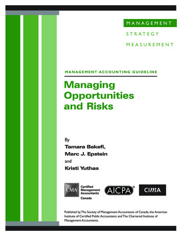
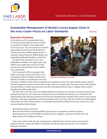
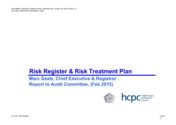
The purpose of FCP is to detect a broken energized conductor and de-energize it before it strikes the ground, eliminating the risk of fire ignition and public exposure to liveequipment. SDG&E and other utilities experience conductor breaks even with vigorous circuit hardening programs.An SDG&E project team invented and patented the concept and scheme of FCP while developing new synchrophasor-based distribution circuit monitoring and protectionsystem technology.Figure 2 shows the time sequence for a broken overhead distribution conductor falling from 30 ft (9 m). Accelerating fromthe moment of the break, one or both ends reach the ground1.37 s later. The FCP scheme can detect the break fromcircuit voltage signatures and issue trip commands so that thebroken circuit section is de-energized 200–500 ms after theevent—when a conductor has fallen only a few feet.Scheme ComponentsThe system utilizes PMU-enabled protection and controlsintelligent electronic devices (IEDs) along a distributioncircuit; an Ethernet circuit-area, high-speed data communication system; and a substation-based phasor data concentrator (PDC) that sends collected synchrophasor streams toan adjacent real-time automation controller. The controller holistically processes all the circuit measurements withalgorithms developed by the SDG&E project team to detecta break between two measurement locations. The controllercan send trip commands to the circuit protection IEDs oncircuit switching devices that can isolate the break, typicallywithin 100 ms. Figure 3 illustrates two typical distributioncircuits radiating from a substation, with arrays of circuitIEDs communicating with the substation scheme controller. Normally open tie switch connections can be included inthe FCP scheme if the switch control IED is also streamingPMU measurements.Substation and Circuit IEDsIEDs participating in circuit FCP include protective relaysat substation circuit breakers and recloser controllers andvoltage monitors distributed along a circuit. The schemeConductor Height (ft)Falling Conductor Protection3025201510500.5 s,4 ft1 s,16 ftConductor Hits Ground at 1.37 s0.250.50.7511.25Time (s)0figure 2. The falling conductor timeline.LM6ASubstationCircuitBreaker4B4A5A ZRCB5B Y7ALM2BY2ARTie SwitchTSection of Circuit Covered byFCP Circuit Protection ZonesIf it has Integrated PMUCapable IEDLegend1A1BZCBSubstationCircuitBreakerSolar Plant,8 MW3APMUsCB Circuit BreakerRRecloserLM Line MonitorTTie Switch#Zone 1 1A, 2A, and 3AZone 2 4B, 5A, and 6AZone 3 5B and 7AFC Testing LocationLMfigure 3. The FCP two-circuit design.january/february 2022IEEE power & energy magazine69
uses commercially available IEDsthat are, in addition to their conventional protection and controland SCADA functions, capableof streaming synchrophasor voltage and current measurements viahigh-speed communication at arate of 30 or 60 synchrophasorsets per second. Figure 4 displaystypical circuit IED installations.If a substation controller detectsa conductor break, it sends highspeed tripping commands to circuit switching devices (reclosers,circuit breakers, and high-speedtransfer switches) over the samecommunication network that collects the synchrophasor measurements used by the algorithms.(a)(b)High-Speed DataCommunicationFigure 5 details how circuit IEDsare coupled to an Ethernet radiofigure 4. The FCP circuit IED locations. (a) The distribution recloser. (b) The linemonitor sensors. (Source: SDG&E.)Primary DistributionControl CenterBackup DistributionControl CenterUtility SCADAWide Area NetworkSCADAMaster RadioMicrowaveBackhaulSCADA ChannelMaster RadioMicrowaveRadioAdvanced SCADAEthernetRadio ControllerDistributionCircuit AreaTraditionalSCADAAdvancedSCADACircuit andMicrowaveAntenna TowerSubstationControlBuildingPDCControllerGPS Clockfigure 5. The FCP radio communication architecture.70IEEE power & energy magazinejanuary/february 2022
network to transport the PMU data stream of 30 to 60 frames/sback to a substation for processing. For returned FCP tripping commands, the controller publishes high-speed trippingcommands using the International Electrotechnical Commission 61850 Generic Object-Oriented Substation Event(GOOSE) message packet specification. Fiber-optic connections are installed in the substation to connect PMU-enabledfeeder relays to the PDC. Fibers along distribution circuitpaths may be available in place of radio paths in selectedservice areas with high load densities.FCP requires robust communication links that provide consistently high data rates and low packet loss rates. Recent FCPdeployments use wideband Ethernet mesh, point-to-point, andpoint-to-multipoint radio systems with repeaters. These radionetworks operate in the U.S. Federal Communication Commission-allocated 2.4- and 5.8-GHz unlicensed bands and cantransport synchrophasor streams with a latency, or time delay,shorter than 50 ms. High-gain directional antennas boost thesignal strength and signal-to-noise ratio for penetrating foliageand other environmental obstacles. Omnidirectional antennasare employed where directionality is not required, due to theirease of installation and use.Figure 5 also shows how the high-speed radio communication for PMU data and tripping is overlaid on SDG&E’slegacy wide-area and lower-speed distribution SCADA radiosystem so that both networks can simultaneously operate asadvanced high-speed data collection and communication arebeing deployed across the company’s distribution system. Thelower-right portion shows a substation-based communicationhub tied to FCP controller system components, as explainedin the following. The substation hub communicates with circuit control devices over high-speed Ethernet radio, shown asthe advanced communication system. Circuit synchrophasormeasurements and FCP system data are transferred to controlcenters via a backhaul connection from a substation throughthe wide area network to control centers. The traditional SCADAcommunication system at the lower right includes a lowerspeed, wide-area radio system exchanging data with circuitdevices across the service area every few seconds. The traditional and advanced communication paths can be overlaid,even on a single circuit.We have pointed out that SDG&E is deploying privatelyowned LTE cellular radio systems for a variety of gridmonitoring and control applications. New FCP deploymentsoperate over this expanding communication network. Thiscommercial off-the-shelf solution features flexible networkrouting and the ability to integrate overlapping zones of coverage between geographical areas for improved reliability.The LTE solution decreases the cost of FCP deployment andimproves cybersecurity management.tion controller, Ethernet switch, and GPS receiver for precisesystem measurement and event timing (Figure 6). In newerdeployments, PDC and FCP functions are combined in anext-generation automation controller.Figure 7 displays the overall interconnection of components for the FCP system. Every circuit IED installationcommunicates with a host radio transceiver node in a substation, as in Figure 5. The radio node exchanges Ethernet datapackets with the PDC and Ethernet network with a real-timescheme automation controller, substation relay PMU, andSCADA communication interface. In some installations, thescheme controller directly communicates with the distribution SCADA system, performing its own SCADA remoteterminal unit function. In some FCP installations, the PDCconcentrates and streams the entire circuit PMU data arrayfrom across the circuit over a wideband backhaul channelto a wide area network data center server (Figure 5). Thesefull PMU measurement records are available to engineersfor near-real-time circuit observation, event analysis, andarchiving as well as the development of other distributionPMU applications, such as circuit voltage and current profile monitoring.Scheme OperationThe controller receives a new set of phasor frames fromacross a monitored circuit 30 or 60 times/s. With each newSubstation Processing ArrayAt the substation terminating each FCP-equipped circuit,the high-speed data radio system host transceiver node iscombined on a rack with a PDC, FCP-programmed automajanuary/february 2022figure 6. The FCP substation IEDs. (Source: SDG&E.)IEEE power & energy magazine71
frame, the controller executes a sequence of five algorithmsthat analyze three-phase voltage relationships across a seriesof frame times. A conductor break produces a unique shift inrelationships among phase voltage magnitudes and angles.For example, Figure 8 shows how a composite extraction ofangles from the three-phase voltages (negative- and zerosequence voltage angles) across the circuit bracket the location of a break.At the moment of a break, the extracted angles shift position, presenting a characteristic difference between angleson either side of the break. A comparison of these extractedangles across the circuit and several synchrophasor frameintervals gives a reliable indication of the section with thebroken conductor and triggers a GOOSE trip command tothe nearest switching devices on either side of the break.The controller delivers a SCADA alarm to the control center to alert an operator to specifics of the FCP isolation of a broken wire. This prompts an immediate fieldresponse to investigate the open circuit section, repair thebreak, and restore service. FCP experts perform postmortem analysis on historized synchrophasor and event recordsto ensure that the system operated correctly and guide algorithm improvements.Circuit FCP PMU–IED LocationsFive algorithms have been developed in extensive laboratory testing on a real-time digital simulation of a real feederwith
that can ignite dry vegetation—the broken con-ductor has no power when it lands. SDG&E is preparing to deploy new transmission line FCP schemes based on PMU measurements, which can trip a line and avoid fire ignition risk in the same way that it does for distr