Transcription
How-to Guide:Supporting DocumentationIn Compliance with2020 New York City Energy Conservation Code GENERAL BUILDING ENVELOPE MECHANICAL SYSTEMS LIGHTING & ELECTRICAL POWER OTHER REQUIREMENTSNOTE: In this How-To Guide: Supporting Documentation, selected Energy Code provisions have been generalized, summarized, rephrased, and/or highlighted. This guide is intended: 1) Toprovide general guidance for the job applications seeking compliance with the 2020 NYCECC; 2) Not to replace or represent the entire 2020 NYCECC and related regulations of the City ofNew York and the Department of Buildings; and 3) Not to provide complete compliance solutions for any particular type of job or work. Comprehensive mandates, applicability, exemptions,exceptions and options will be found in the 2020 NYCECC and related regulations of the City of New York and the Department of Buildings.
OVERVIEWWhat is Supporting Documentation?1 RCNY §5000-01(g)1 RCNY §5000-01(e)ECC 101.5.2.3ECC 103 A Requirement to Demonstrate Compliance with NYCECC- Supporting Documentation is required for all job applications that are not exempt from the NYCECC in accordance with 1 RCNY §5000-01 (e)(2).- Job applications submitted through DOB BIS indicating NYCECC Compliance in the PW1-Section 10 must submit supporting documentation throughDOB BIS.- Job applications with Work Types requiring DOB NOW filing must submit supporting documentation through DOB NOW.- See Quick Reference Guide: How to Demonstrate Energy Code Compliance for the summary list of requirements.- Exempt from the NYCECC Job applications claiming exemption from the 2020 NYCECC must :- Complete PW1-Section 10 to indicate the job is eligible to be exempt from the NYCECC, for DOB-BIS-filed jobs.- On drawings, provide Professional Statement for exemption (similar to the statement in PW1-Section 10), and specify the basis for exemption inaccordance with 1 RCNY §5000-01 (e)(2).- On drawings, provide a simple Tabular Analysis listing the proposed work types and summary work scope to validate the exemption. Essentially, Construction Documents- To be submitted to the Department of Buildings for approval.- To inform means and methods of construction for all energy design elements in the form of technical drawings, schedules, specification notes, etc.- To prove that all proposed energy design elements will match or exceed the requirements of the NYCECC in their quality, quantity, size, capacity,efficiency, performance, location, configuration, composition, etc. Must Match the Proposed Work Type and ScopeSupporting Documentation (Construction Documents) must provide construction data to match all proposed Work Types and work scope indicated in- DOB BIS PW1-Section 6 Work Types- DOB NOW filed Work Types, such as Mechanical Systems (MS), Plumbing (PL), and Boiler Equipment (BE)- TR8-Section 3 and Section 4 Must Support Energy Analysis- Construction Documents must support the Energy Analysis reports. Specifically, the values and attributes of any energy-code-regulated elementproposed in the construction documents must match or exceed those of the same element listed in the Energy Analysis (e.g., Tabular analysis,REScheck, COMcheck, and EN1).- Supporting Documentation and Energy Analysis must be submitted along with its associated work type either through DOB BIS or DOB NOW asrequired.- Job applications with Energy Modeling analysis must submit the completed EN1 workbook along with the primary job filed through DOB BIS. Refer to Page [GE-5] for Energy Analysis options.GENERAL [GE - 1]BUILDING ENVELOPEMECHANICAL SYSTEMSLIGHTING & ELECTRICAL POWEROTHER REQUIREMENTS
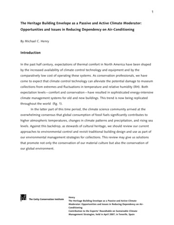
KEY PRINCIPLESHow Should Supporting Documentation be Prepared?1 RCNY §5000-01(g)ECC 101.5.2.3ECC 103 Identify a Correct Code Version to Follow- Job applications filed on and after May 12, 2020 must comply with the 2020 NYCECC.- Job applications filed between October 3, 2016 and May 11, 2020 must comply with the 2016 NYCECC.- Refer to ‘What Codes, Rules & Forms Apply When’ to identify which ECC Code version is applicable for a particular jobapplication. Identify Correct Code Sections to Follow- Mandatory provisions must be satisfied by all applications, whereas Prescriptive provisions must be satisfied by applications that seek to provecompliance prescriptively.- Applicable Code sections must be carefully identified and selected according to the job application/project type.- For a Commercial building application, the Single chosen Code (NYCECC or ASHRAE; indicated as the Code compliance path on PW1–Section 10)must be referenced throughout the entire set of construction documents.Figure GE-2.2020 NYCECC and Applicable Job TypesResidential Buildings2020 NYCECCCommercial Buildings w.NYCECC as Code Compliance PathCommercial Buildings w.ASHRAE as Code Compliance PathNew BuildingsExisting BuildingsNew BuildingsExisting BuildingsNew BuildingsExisting BuildingsChapter 1AdministrationvvvvvvChapter R2DefinitionsvvChapter R3General RequirementsvvChapter R4Residential Energy EfficiencyvChapter R5Existing BuildingsChapter R6Referenced StandardsChapter C2DefinitionsvvChapter C3General RequirementsvvChapter C4Commercial Energy EfficiencyvChapter C5Existing BuildingsChapter C6Referenced StandardsAppendix CAModified Energy Standard for Buildings, Exceptfor Low-Rise Residential Buildings(ASHRAE 90.1-2016 with NYC Modifications)vvGENERAL [GE - 2]BUILDING ENVELOPEvvvvvMECHANICAL SYSTEMSvLIGHTING & ELECTRICAL POWEROTHER REQUIREMENTS
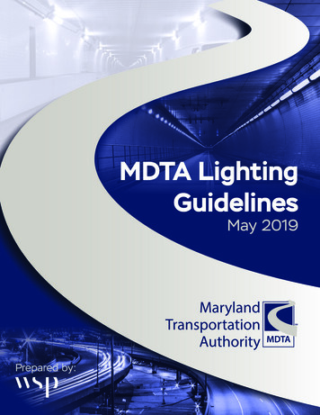
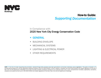
KEY PRINCIPLESHow Should Supporting Documentation be Prepared?1 RCNY §5000-01(g)ECC 101.5.2.3ECC 103 Label Energy Design Elements Consistently Among Drawings- Identification keys for all proposed energy design elements, such as wall types, window/door types, light fixture types, mechanical equipmentsystem types, etc., must be consistent between Supporting Documentation and Energy Analysis. Values and Attributes Must Match- Specifications (in values and attributes) of energy design elements reported in Energy Analysis must be validated through SupportingDocumentation. For example, Energy-Code-relevant specifications (e.g., insulation type, R-value, U-factor, luminaire type, luminaire wattage,equipment size, equipment efficiency, etc.) declared in the COMcheck energy analysis, but not identified in the construction documents will not beaccepted for Energy Code compliance.- Total numbers reported in Energy Analysis must be validated through Supporting Documentation. For example, the gross values such as exteriorwall/fenestration areas, roof/floor areas, luminaire/equipment counts, area-weighted average values, etc. listed in the Tabular energy analysismust be easily identified in the drawings, schedules, and/or diagrams provided in the construction documents.Figure GE-3.Sample Lighting Fixture Layout Plan (top left),Matching Fixture Schedule (top right), andMatching Interior Lighting COMcheck Report (bottom right)GENERAL [GE - 3]BUILDING ENVELOPEMECHANICAL SYSTEMSLIGHTING & ELECTRICAL POWEROTHER REQUIREMENTS
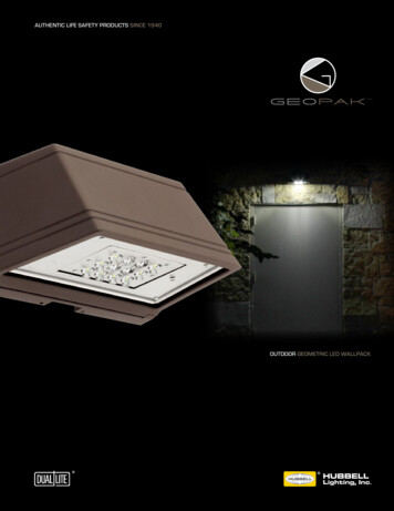
KEY PRINCIPLESHow Should Supporting Documentation be Prepared?1 RCNY §5000-01(g)ECC 101.5.2.3ECC 103 Specific Design Data in Proper Locations- Specific design values and characteristics proposed for the work scope in the application must be provided in the construction documents insufficient detail and clarity. For example, window schedules on drawings must list each proposed window assembly’s U-factor, SHGC, air leakagerating, and Visible Transmittance (as required) values furnished/published by the respective window manufacturer.- Notes directly relevant to achieve the proposed design must be provided in the construction documents in sufficient detail and clarity. In otherwords, mere duplicates of general Energy Code sections placed on the drawings will not be construed as Energy Code compliance.- In proper locations within construction documents, construction data must be presented. For example, 1) HVAC mechanical equipment schedulesand a sequence-of-operations narrative must be found on Mechanical drawings; 2) Lighting control notes must be placed in conjunction withlighting fixture plans and schedules on drawings (typically on RCP drawings). List of Progress Inspections on EN- Sheet- All applicable progress inspections required for Energy Code compliance must be listed on an EN- labeled sheet in tabular format as shown in 1RCNY §5000-01(h), and must match those identified on the TR8.AIR HANDLING UNIT SCHEDULEAIR FLOWTAG LOCATIONROOFCHILLED WATERAREAAIRMINEAT EAT LATSERVED FLOW SUPPLY OA RETURN TSP BHP HP PH/V/RPM Db Wb DbCFMAHU-1SUPPLY FAN3 NORTH VAVCFMCFMINCFMRECOVERERYWHEELHOT WATERLATWbTOT. SENS.TOT. SENS.FLOW EWT LWT EAT LATFLOW EWT LWTCAP CAP.CAP CAP F F F FMBHMBHGPM F F F F MBHMBHGPM3/460/17526000 5500 20500 4.7 23.5 25800675554380270474258 459027049480 F F160 140ENTHALPY%NOTE 3NOTES:1. PROVIDE MOTORIZED SHUT-OFF DAMPER AT THE OA INTAKE WITH MAXIMUM LEAKAGE RATE OF 4 CFM/SF AT 1 IN. WG. DAMPER SHALL CLOSE WHEN THE UNIT IS OFF.2. IN ECONOMIZER MODE, MINIMUM OCCUPIED AIRFLOW SETPOINT ON VAV TERMINALS SHALL BE AUTOMATICALLY RESET BASED ON PERCENTAGE OF OUTSIDE AIR ABOVE DESIGN MINIMUM.A. AS PERCENTAGE OF OA DAMPER AT 100% AND AS ECONOMIZER OUTPUT INCREASES FROM 0-100%, MINIMUM AIRFLOW SETPOINT AT TERMINAL UNITS SHALL PROPORTIONATELY RESET LOWER TOMAINTIAN REQUIRED MINIMUM FRESH AIR VENTILATION.B. RESETTING SHALL OCCUR BASED ON INCREEMENTS OF 10% CHANGE OF VALUE OF ECONOMIZER OUTPUT.3. PROVIDE HEAT WHEEL THAT SHALL RECOVER MINIMUM 50% OF THE ENTHALPY. HEATWHEEL SHALL CONTAIN A BYPASS FOR ECONOMIZER MODE.4. AT A MINIMUM, ALL VAV TERMINAL UNITS SERVED BY AN AHU SHALL BE LINKED WITH ASSOCIATED VAV AHU CONTROLLER TO PERFORM THE FOLLOWING FUNCTIONS.A. ZONE OCCUPANCY SCHEDULE (USER DEFINED FROM GRAPHIC INTERFACE) SHALL NORMALLY AUTOMATICALLY SELECT THE OCCUPIED OR UNOCCUPIED OPERATING MODE OF AIR HANDLING UNIT.1) ACTIVATION OF TIMED OVERRIDE SWITCH ON ZONE THERMOSTATS SHALL ONLY RESET ZONE HEATING AND COOLING SETPOINTS TO “OCCUPIED” VALUES, BUT SHALL NOT AFFECT OTHERWISESCHEDULED UNOCCUPIED OPERATING MODE OF AIR HANDLING UNIT.B. DUCT STATIC PRESSURE RESET AS DESCRIBED IN FAN CONTROL SECTION.C. DISCHARGE AIR TEMPERATURE SETPOINT –OPTIMIZED AS DESCRIBED IN THE DISCHARGE TEMPERATURE CONTROL SECTION.5. FAN POWER LIMITATION CHECK -- PER Table C403.2.12.1(1)HP CFM x 0.001525 26000 x 0.0015 39 OKGENERAL [GE - 4]BUILDING ENVELOPEFigure GE-4. Sample Mechanical Equipment Schedule and NotesMECHANICAL SYSTEMSLIGHTING & ELECTRICAL POWEROTHER REQUIREMENTS
ENERGY ANALYSISto Demonstrate ECC Compliance in conjunction with Supporting Documentation* Refer to Quick Reference Guide: How to Demonstrate Energy Code Compliance for more information.1 RCNY §5000-01(f)ECC 101.5.2.2Figure GE-5.Energy Analysis MethodsGENERAL [GE - 5]BUILDING ENVELOPEMECHANICAL SYSTEMSLIGHTING & ELECTRICAL POWEROTHER REQUIREMENTS
How-to Guide:Supporting DocumentationIn Compliance with2020 New York City Energy Conservation Code GENERAL BUILDING ENVELOPE MECHANICAL SYSTEMS LIGHTING & ELECTRICAL POWER OTHER REQUIREMENTSNOTE: In this How-To Guide: Supporting Documentation, selected Energy Code provisions have been generalized, summarized, rephrased, and/or highlighted. This guide is intended: 1) Toprovide general guidance for the job applications seeking compliance with the 2020 NYCECC; 2) Not to replace or represent the entire 2020 NYCECC and related regulations of the City of NewYork and the Department of Buildings; and 3) Not to provide complete compliance solutions for any particular type of job or work. Comprehensive mandates, applicability, exemptions, exceptionsand options will be found in the 2020 NYCECC and related regulations of the City of New York and the Department of Buildings.
OPAQUE ENVELOPE ASSEMBLIES Minimum R-value- For each building envelope type (e.g., roof, above-grade/below-grade walls, floors over unconditioned space, etc.), its section detailmust indicate that the R-value of the insulation meets or exceeds the minimum allowed R-value prescribed for the envelope type(e.g., R-values shown in Table C402.1.3).R402.1.3C402.1.35.5.3- Specifically, in the assembly details, clearly call out each of the proposed insulation type, thickness and the manufacturerpublished R-value to satisfy the thermal requirements for the envelope assembly type. Maximum U-factor- Alternatively, it must be demonstrated that the proposed assembly’s calculated U-factor (or C- or F-factor) value does not exceedthe maximum allowed U-factor value prescribed for the envelope type (e.g., U-factors shown in Table C402.1.4).- Determination of an assembly’s overall U-factor (or C- or F-factor) value must be supported by the pre-calculated values or thecalculation methods established in Appendix A of ASHRAE 90.1-2016.R402.1.4C402.1.45.5.3- Spandrel Panels are Opaque walls. Determination of effective U-factors for the proposed Spandrel Panels must follow TableC402.1.4.2/ Table 5.5.3. See page [BE-9]. The proposed U-factor value identified from the Table must be compared against thebaseline U-factor of metal-framed walls (U-0.061) in COMcheck. NOTE: One common error in the U-factorcalculation is misrepresenting thermalvalues of assembly layers (e.g., facebrick, gypsum board, air films, etc.) fromunapproved sources.Figure BE-1. Sample Wall Assembly & Area-Weighted U-factor CalculationGENERALBUILDING ENVELOPE [BE - 1]MECHANICAL SYSTEMSLIGHTING & ELECTRICAL POWEROTHER REQUIREMENTS
WINDOWS & DOORS – FENESTRATION IN THE ENVELOPE U-factor and SHGC values- For each fenestration type (e.g., fixed/operable window, skylight, exterior door, storefront, etc.), Assembly U-factor and Solar HeatGain Coefficient (SHGC) values must be specified in the window/door schedule on drawings, and must not exceed the maximumallowed values. For Commercial building windows, the maximum assembly U-factors depend on the vertical location of the windowon the above-grade wall, with more stringent U-factors for windows installed below 95’ above-grade. See page [BE-3]. The 95’demarcation line must be indicated on building elevation drawings for Commercial buildings.R402.3C402.45.5.4.35.5.4.41 RCNY§5000-01(g)(1)(i)- Next to the U-factor and SHGC values specified in the schedule, provide the fenestration assembly manufacturer’s information (e.g.,‘ABC Windows/xyz 9000 series, or Approved equal’) that will satisfy the U-factor and SHGC requirements. Air Leakage Rate and Visible Transmittance (VT)- The window/door schedule on drawings must specify the air leakage rate of each proposed fenestration assembly type todemonstrate that the air leakage of fenestration assemblies do not exceed the maximum allowed leakage rate.- Where required, the window/door schedule must identify Visible Transmittance (VT) of the proposed glazed fenestrationproducts to meet the provisions in the applicable Code sections.R402.4C402.5.2/ 5.4.3.2R303.1.3C303.1.3/ C402.4.1C405.2.3/ 5.5.4.6WINDOW & DOOR SCHEDULETAGTYPEFRAJEMATERIALNOMINAL DIM.(W X H)MANUFACTURER - MODEL NO.ASSEMBLYU-FACTORSHGCVTAIR LEAKAGERATE (CFM/SF)W1FIXEDMETAL7'-0" X 7'-0"ABC WINDOWS - D999 SERIESOR APPROVED EQUAL0.280.340.500.16W2CASEMENT - OPERABLEMETAL4'-6" X 2'-3"ABC WINDOWS -EF00 SERIESOR APPROVED EQUAL0.380.340.500.18SW1SKYLIGHTMETAL2'-10" X 5'-2"SKL CORP. - GHT000 SERIESOR APPROVED EQUAL0.460.380.540.18W5STOREFRONT - FIXEDGLAZINGMETALVARIES; SEE A-301 305FOR LOCATIONS & DIM.GLD CO. - STR #Z111 ORAPPROVED EQUAL0.300.340.500.05D1STOREFRONT ENTRANCE GLASS DOORMETAL3'-0" X 7'-6"GLD CO. - STR #Z111 ORAPPROVED EQUAL0.700.360.520.80D2OPAQUE SWINGINGDOORMETAL3'-0" X 7'-0"OPQ COMPANY RST-#22-33 ORAPPROVED EQUAL0.48N/AN/A0.80Figure BE-2. Sample Window & Door Schedule Fenestration U-factor values must be the ‘whole assembly’ U-factor, instead of ‘center-of-glass’ U-factor, and must be furnished by the manufacturer. Differentiate Fixed and Operable windows’ U-factor values in the window schedule where required, as the Code-prescribed maximum U-factors forFixed and Operable windows may vary depending on the referenced Code.GENERALBUILDING ENVELOPE [BE - 2]MECHANICAL SYSTEMSLIGHTING & ELECTRICAL POWEROTHER REQUIREMENTS
SPANDREL PANEL EFFECTIVE U-FACTORSC402.1.4.25.5.3 NOTE 1: To demonstrate compliance,provide COMcheck envelope analysis by:- entering the Proposed Spandrel panel Ufactor value identified from the TableC402.1.4.2; and- choosing the Baseline U-factor of metalframed walls (U-0.061). NOTE 2: If the Proposed Spandrel paneltype is not found in the Table – e.g.,Assembly with backpans, Assembly with noinsulation – THERM Analysis must beperformed and documented on drawings.COMMERCIAL BUILDING FENESTRATION MAXIMUM U-FACTORSInfo for THERM is found in the link 5.5.4.3 NOTE: Where any portion of thewindow unit is installed above 95’above-grade, U-factor requirementof 95’ and above may apply.See Table 5.5-4 for ASHRAE-following job applications.GENERALBUILDING ENVELOPE [BE - 3]MECHANICAL SYSTEMSLIGHTING & ELECTRICAL POWEROTHER REQUIREMENTS
CONTINUOUS INSULATION Balconies and ParapetsBalconies and Parapets that interrupt the building thermal envelope are required to be:a) Insulated with continuous insulation of a minimum R-value for the wall assembly as listed in Table C402.1.3/ Table 5.5-4. ORb) Insulated with a minimum R-3 thermal break where the structural element penetrates the building thermal envelope. NOTE: Compliance with thecontinuous insulationrequirements on balconies andparapets does not relievecompliance requirements ofother applicable ConstructionCodes. For example, BC Chapter16 and Chapter 33 requirementsmust be met for parapets in caseof future C-hooks/ clamps use onthe parapet walls.C402.2.95.5.3.7To report R-value of Parapet as a Roof componentin COMcheck Envelope Analysis, click Here.To report R-value of Balcony slab as a Wallcomponent in COMcheck Envelope Analysis,refer to [BE- 11].a) COMPLIANT with C402.2.9/ 5.5.3.7b) NOT COMPLIANT with C402.2.9/ 5.5.3.7Figure BE-4. Examples of Balcony and Parapet InsulationGENERALBUILDING ENVELOPE [BE - 4]MECHANICAL SYSTEMSLIGHTING & ELECTRICAL POWEROTHER REQUIREMENTS
FENESTRATION AREAThe Window-to-Wall Ratio (WWR) -- the ratio (%) of vertical fenestration area to gross above-grade wall area (or gross wall area forAppendix CA applications) -- must be noted on an EN- labeled drawing in conjunction with building envelope diagrams and theenvelope energy analysis. The building envelope diagrams must list all opaque wall areas and vertical fenestration areas per eachbuilding orientation. The area values of each opaque wall type and fenestration type listed in the envelope diagrams must matchthe values entered in the envelope energy analysis (e.g., ‘Gross Area’ values in COMcheck). Maximum Vertical Fenestration Area (when following ECC)C402.4.1- Maximum WWR:30%- Maximum WWR:40% permitted with certain requirements including daylight responsive controls- When WWR 40%:ASHRAE must be chosen as Code Compliance Path, as ECC does not allow WWR 40%. Maximum Vertical Fenestration Area (when following ASHRAE)- Maximum WWR:5.5.4.2.140%- When WWR 40%:Energy Code compliance may be demonstrated through eithera) COMcheck (with envelope tradeoff) envelope analysis, orb) Energy Modeling (total building performance) energy analysis. Maximum Skylight Fenestration Area- Maximum skylight fenestration area:3% of the gross roof area- Maximum skylight fenestration area:6% of the gross roof area permitted with daylight responsive controlsC402.4.15.5.4.2.2 Minimum Skylight Fenestration Area- For an enclosed space 2,500 sf, and directly under a roof with ceiling height 15’ and of space types including office, lobby, atrium, concourse, corridor, warehouse storage, among othersMinimum skylight fenestration area requirement:C402.4.25.5.4.2.3Minimum 3% of the gross roof area, orMinimum 1% ‘Skylight Effective Aperture’- See Section C402.4.2 and 5.5.4.2.3 for complete applicable space types, minimum total daylight area requirement, anddefinition of ‘Skylight Effective Aperture.’GENERALBUILDING ENVELOPE [BE - 5]MECHANICAL SYSTEMSLIGHTING & ELECTRICAL POWEROTHER REQUIREMENTS
AIR BARRIER Continuous Air BarrierTo ensure air barrier continuity in the building thermal envelope, drawings must specify required continuous air barrier constructionmeasures (Section C402.5.1.1), and indicate that the continuous air barrier shall be achieved by either1) Materials not exceeding maximum allowed air permeability (Section C402.5.1.2.1), or2) Assemblies not exceeding allowed maximum air leakage (Section C402.5.1.2.2).C402.5.15.4.3.1.25.4.3.1.3 Openings in the Building EnvelopeDrawings must identify specific construction measures, configuration, devices and/or performance standards to limit air leakagein particular envelope areas including, but not limited to, the following:1) Fenestration and doors: Maximum allowed air leakage.2) Outdoor air intakes and exhaust openings: Motorized Shutoff dampers are required unless gravity dampers are allowed.3) Doors/Access Openings to shafts, chutes, vents, stairways and elevator lobbies: Gasketing, weatherstripping, and sealing.4) Loading dock: Weatherseals to restrict infiltration.5) Vestibules*: Plan configuration and self-closing devices on doors.* Note that Air Curtains are NO longer an acceptable alternative.6) Recessed lighting: Luminaires installed in building envelope must be:a) IC-rated, b) Labeled with the Code-prescribed maximum air leakage rate, and c) Sealed with gasket or .3.4C402.5.8/5.4.3.1.1Figure BE-6.A Sample Acceptable Plan with Specific Notes Requiring Future ComplianceGENERALBUILDING ENVELOPE [BE - 6]MECHANICAL SYSTEMSLIGHTING & ELECTRICAL POWEROTHER REQUIREMENTS
AIR LEAKAGE/BARRIER TESTING & AIR BARRIER CONTINUITY PLAN – NEW BUILDINGSDrawings must specify mandatory air barrier testing/inspection requirements specific to the building type. Residential Buildings – See R202 for the definition of Residential Building1 RCNY §5000-01 (g)(5)(iv)Building TypesRequired Testing/InspectionRequired Progress Inspections Reference CodeR402.4.1.2(A) AND (B)IA6 AND IA7 New buildings with 1 dwelling unitR402.4.1.3(A) AND (B) or (C)IA6 AND IA7 New buildings with dwelling units 2R402.4.1.3.1(A)AND(B)or(D)IA6ANDIA7 New buildings with dwelling units 8(A) Visual Inspection of Air BarrierVisual inspection of openings and penetrations in the building envelope, including site-built fenestration and doors to verify continuous air barrier installation(B) Whole Building Air Leakage Testing [maximum 3 ACH]Testing conducted at a pressure differential of 50 Pascals must verify that the Building air leakage rate does not exceed 3 air changes per hour (3 ACH).(C) Air Leakage Testing of ALL “Testing Units”Testing conducted at a pressure differential of 50 Pascals must verify that the air leakage rate of EACH testing unit does not exceed 0.3 cfm/sf of the testing unitenvelope.(D) Air Leakage Testing of SAMPLE “Testing Units”Testing conducted at a pressure differential of 50 Pascals must verify that the air leakage rate of EACH Sample testing unit does not exceed 0.3 cfm/sf of the testingunit envelope. SAMPLE Testing Unit selection must follow the code provision. Commercial Buildings – See C202 for the definition of Commercial Building1 RCNY §5000-01 (g)(5)(iv)Building types New buildings with conditioned space 10,000 sfRequired Testing/Inspection(A)Required Progress Inspections Reference code1 RCNY §5000-01IIA6 New buildings with conditioned space 10,000 sf and 50,000 sf, andHeight 75’(A) AND (E)IIA6 AND IIA7 R-2 occupancy Only: New Buildings with conditioned space 10,000 sf and 50,000 sf, and Height 75’(A) AND (E) or (D)IIA6 AND .4.3.1.35.9C402.5.1.35.4.3.1.35.9(A) AND (F) or (D) or (E)IIA6 AND IIA8 or IIA7 New buildings with conditioned space 10,000 sf and 50,000 sf, andHeight 75’ New buildings with conditioned space 50,000 sfC401.2.1(A) AND (B) or (C)IIA6 AND IIA7 R-3 occupancy Only: all New Buildings(E) Whole Building Air Leakage Testing [maximum 0.4 cfm/sf]Testing conducted at a pressure differential of 75 Pascals must verify that the Building air leakage rate does not exceed 0.4 cfm/sf of the building envelope.(F) Testing/Inspection conducted per Air Barrier Continuity (ABC) PlanAir Barrier Continuity Plan must be developed to specify the below.- List (Schedule of Details) of each unique assembly, joint, seam and penetration, keyed to building thermal/air boundary section diagrams (on Architectural Plans)- Testing/Inspection standards (e.g., ASTM E1186) and performance criteria for each assembly, joint, seam and penetration type (on Architectural Plans)- Specifications of sealing (continuity-ensuring) materials/measures, and Remediation procedures- Sampling protocol, if applicable, and Test reporting/submittal guidelinesABC Plan, and Final Reports of Testing/Inspection conducted per the ABC Plan shall be provided to DOB upon request.GENERALBUILDING ENVELOPE [BE - 7]MECHANICAL SYSTEMSLIGHTING & ELECTRICAL POWEROTHER REQUIREMENTS
AIR LEAKAGE/BARRIER TESTING & AIR BARRIER CONTINUITY PLAN -- ADDITIONS & ALTERATIONSDrawings must specify mandatory air barrier testing/inspection requirements specific to the building type. Residential Buildings – See R202 for the definition of Residential Building1 RCNY §5000-01 (g)(5)(iv), R502, R503Building TypesRequired Testing/InspectionRequired Progress Inspections Reference CodeR402.4.1.(A)IA6 Any Additions Alterations to the existing building envelopeR402.4.1.2(A) AND (B)IA6 AND IA7 Additions thermally isolated from the existing building envelope Alterations of the entire existing building envelope including air barrierR402.4.1.3(A) AND (B) or (C)IA6 AND IA7 Additions with dwelling units 2R402.4.1.3.1(A) AND (B) or (D)IA6 AND IA7 Additions with dwelling units 8(A) Visual Inspection of Air BarrierVisual inspection of openings and penetrations in the building envelope, including site-built fenestration and doors to verify continuous air barrier installation(B) Whole Building Air Leakage Testing [maximum 3 ACH]Testing conducted at a pressure differential of 50 Pascals must verify that the Building air leakage rate does not exceed 3 air changes per hour (3 ACH).(C) Air Leakage Testing of ALL “Testing Units”Testing conducted at a pressure differential of 50 Pascals must verify that the air leakage rate of EACH testing unit does not exceed 0.3 cfm/sf of the testing unitenvelope.(D) Air Leakage Testing of SAMPLE “Testing Units”Testing conducted at a pressure differential of 50 Pascals must verify that the air leakage rate of EACH Sample testing unit does not exceed 0.3 cfm/sf of the testingunit envelope. SAMPLE Testing Unit selection must follow the code provision. Commercial Buildings – See C202 for the definition of Commercial Building1 RCNY §5000-01 (g)(5)(iv), C502, C503Building typesRequired Testing/InspectionRequired Progress Inspections Reference code1 RCNY §5000-01(A)IIA6 Additions with conditioned space 10,000 sf(g)(5)(iv), C503.3 Alterations to the existing building envelopeC402.5.1.3(A) AND (E)IIA6 AND IIA7 Additions with conditioned space 10,000 sf and 50,000 sf, & Height 75’5.4.3.1.3 Alterations of the entire existing building envelope including air barrierC402.5.1.3(A) AND (E) or (D)IIA6 AND IIA7 R-2 occupancy Only: Additions with conditioned space 10,000 sf and 5.4.3.1.350,000 sf, and Height 7 Additions with conditioned space 10,000 sf and 50,000 sf, & Height 75’5.4.3.1.3 Additions with conditioned space 50,000 sfC401.2.1(A) AND (B) or (C)IIA6 AND IIA7 R-3 occupancy Only: Additions thermally isolated from the existing buildingenvelope(E) Whole Building Air Leakage Testing [maximum 0.4 cfm/sf]Testing conducted at a pressure differential of 75 Pascals must verify that the Building air leakage rate does not exceed 0.4 cfm/sf of the building envelope.(F) Testing/Inspection conducted per Air Barrier Continuity (ABC) PlanAir Barrier Continuity Plan must be developed to specify the below.- List (Schedule of Details) of each unique assembly, joint, seam and penetration, keyed to building thermal/air boundary section diagrams (on Architectural Plans)- Testing/Inspection standards (e.g., ASTM E1186) and performance criteria for each assembly, joint, seam and penetration type (on Architectural Plans)- Specifications of sealing (continuity-ensuring) materials/measures, and Remediation procedures- Sampling protocol, if applicable, and Test reporting/submittal guidelinesABC Plan, and Final Reports of Testing/Inspection conducted per the ABC Plan shall be provided to DOB upon request.GENERALBUILDING ENVELOPE [BE - 8]MECHANICAL SYSTEMSLIGHTING & ELECTRICAL POWEROTHER REQUIREMENTS
THERMAL BRIDGES IN BUILDING ENVELOPE Documentation of Thermal Bridges- Architectural plan set drawings must report all thermal bridges in the building thermal envelope in three categories below.- Documentation requirements apply to Residential and Commercial buildings for all New buildings, Additions, and Alterations to thebuilding envelope work scope.CategoryDefinitionCLEAR FIELD Thermal BridgeArea-based thermal transmittanceassociated with elements of a buildingenvelope assembly which repeat atregular intervals.Most clear field thermal bridges aretaken into account in the assembly typesfound in ASHRAE 90.1-2016 Appendix A.TypicalAssembliesPOINT Thermal BridgeElement-based thermal transmittanceassociated with a discrete element thatpenetrates the building envelope.Point thermal transmittance is heat flowdivided by the temperature differencebetween the interior and exterior sidesof the assembly, represented by a Χvalue (Chi-Value) in units Bt
How-to Guide: Supporting Documentation In Compliance with 2020 New York City Energy Conservation Code . - To inform means and methods of construction for all energy design elements in the form of technical drawings, schedules, specification notes, etc. .